ESP JAGUAR XJ6 1997 2.G Owner's Manual
[x] Cancel search | Manufacturer: JAGUAR, Model Year: 1997, Model line: XJ6, Model: JAGUAR XJ6 1997 2.GPages: 227, PDF Size: 7.2 MB
Page 100 of 227
headlights or heated rear window and confirm
that the engine rpm decreases at first and
then increases. This check monitors the ISC
motor as it is signalled by the computer to
increase idle speed due to additional
amperage required from the charging system.
As the headlights draw current from the
charging system, the alternator will create
resistance on the belt as it works to produce
the additional energy. If the rpm does not
increase, check the ISC motor.
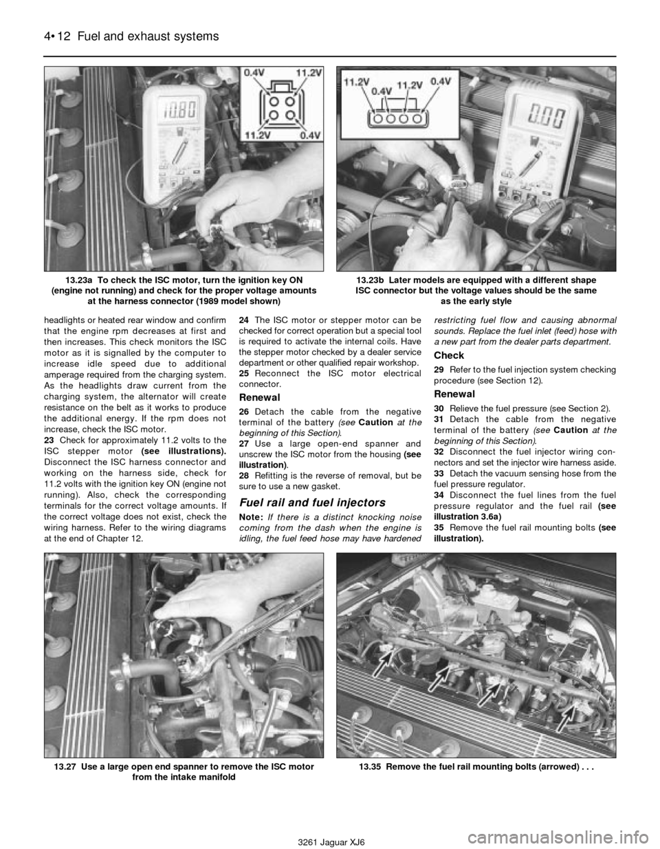
23Check for approximately 11.2 volts to the
ISC stepper motor (see illustrations).
Disconnect the ISC harness connector and
working on the harness side, check for
11.2 volts with the ignition key ON (engine not
running). Also, check the corresponding
terminals for the correct voltage amounts. If
the correct voltage does not exist, check the
wiring harness. Refer to the wiring diagrams
at the end of Chapter 12.24The ISC motor or stepper motor can be
checked for correct operation but a special tool
is required to activate the internal coils. Have
the stepper motor checked by a dealer service
department or other qualified repair workshop.
25Reconnect the ISC motor electrical
connector.
Renewal
26Detach the cable from the negative
terminal of the battery (see Cautionat the
beginning of this Section).
27Use a large open-end spanner and
unscrew the ISC motor from the housing (see
illustration).
28Refitting is the reverse of removal, but be
sure to use a new gasket.
Fuel rail and fuel injectors
Note:If there is a distinct knocking noise
coming from the dash when the engine is
idling, the fuel feed hose may have hardenedrestricting fuel flow and causing abnormal
sounds. Replace the fuel inlet (feed) hose with
a new part from the dealer parts department.
Check
29Refer to the fuel injection system checking
procedure (see Section 12).
Renewal
30Relieve the fuel pressure (see Section 2).
31Detach the cable from the negative
terminal of the battery (see Cautionat the
beginning of this Section).
32Disconnect the fuel injector wiring con-
nectors and set the injector wire harness aside.
33Detach the vacuum sensing hose from the
fuel pressure regulator.
34Disconnect the fuel lines from the fuel
pressure regulator and the fuel rail (see
illustration 3.6a)
35Remove the fuel rail mounting bolts (see
illustration).
4•12 Fuel and exhaust systems
3261 Jaguar XJ6 13.23a To check the ISC motor, turn the ignition key ON
(engine not running) and check for the proper voltage amounts
at the harness connector (1989 model shown)
13.23b Later models are equipped with a different shape
ISC connector but the voltage values should be the same
as the early style
13.27 Use a large open end spanner to remove the ISC motor
from the intake manifold13.35 Remove the fuel rail mounting bolts (arrowed) . . .
Page 101 of 227
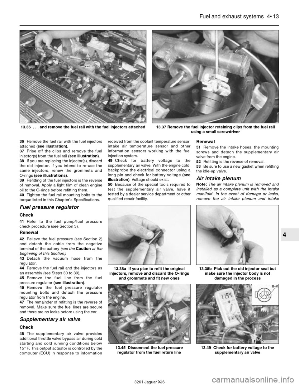
36Remove the fuel rail with the fuel injectors
attached (see illustration).
37Prise off the clips and remove the fuel
injector(s) from the fuel rail (see illustration).
38If you are replacing the injector(s), discard
the old injector. If you intend to re-use the
same injectors, renew the grommets and
O-rings (see illustrations).
39Refitting of the fuel injectors is the reverse
of removal. Apply a light film of clean engine
oil to the O-rings before refitting them.
40Tighten the fuel rail mounting bolts to the
torque listed in this Chapter’s Specifications.
Fuel pressure regulator
Check
41Refer to the fuel pump/fuel pressure
check procedure (see Section 3).
Renewal
42Relieve the fuel pressure (see Section 2)
and detach the cable from the negative
terminal of the battery (see the Cautionat the
beginning of this Section).
43Detach the vacuum hose from the
regulator.
44Remove the fuel rail and the injectors as
an assembly (see Steps 30 to 39).
45Remove the fuel line from the fuel
pressure regulator (see illustration).
46Remove the fuel pressure regulator
mounting bolts and detach the pressure
regulator from the engine.
47The remainder of refitting is the reverse of
removal. Make sure the fuel lines are secure
and there are no leaks before using the car.
Supplementary air valve
Check
48The supplementary air valve provides
additional throttle valve bypass air during cold
starting and cold running conditions below
15° F. This output actuator is controlled by the
computer (ECU) in response to informationreceived from the coolant temperature sensor,
intake air temperature sensor and other
information sensors working with the fuel
injection system.
49Check for battery voltage to the
supplementary air valve. With the engine cold,
backprobe the electrical connector using a
long pin and check for battery voltage (see
illustration). Voltage should exist.
50Because of the special tools required to
test the supplementary air valve, have it
tested by a dealer service department or other
qualified repair facility.
Renewal
51Remove the intake hoses, the mounting
screws and detach the supplementary air
valve from the engine.
52Refitting is the reverse of removal.
53Be sure to use a new gasket when refitting
the idle-up valve.
Air intake plenum
Note:The air intake plenum is removed and
installed as a complete unit with the intake
manifold. In the event of damage or leaks,
remove the air intake plenum and intake
Fuel and exhaust systems 4•13
4
3261 Jaguar XJ6 13.36 . . . and remove the fuel rail with the fuel injectors attached
13.37 Remove the fuel injector retaining clips from the fuel rail
using a small screwdriver
13.45 Disconnect the fuel pressure
regulator from the fuel return line
13.38b Pick out the old injector seal but
make sure the injector body is not
damaged in the process13.38a If you plan to refit the original
injectors, remove and discard the O-rings
and grommets and fit new ones
13.49 Check for battery voltage to the
supplementary air valve
Page 104 of 227
same dimensions, amperage rating, cold
cranking rating, etc. as the original.
6Refitting is the reverse of removal.
4 Battery cables-
check and renewal
1
Caution: If the stereo in your vehicle is
equipped with an anti-theft system, make
sure you have the correct activation code
before disconnecting the battery.
1Periodically inspect the entire length of
each battery cable for damage, cracked or
burned insulation and corrosion. Poor battery
cable connections can cause starting
problems and decreased engine performance.
2Check the cable-to-terminal connections at
the ends of the cables for cracks, loose wire
strands and corrosion. The presence of white,
fluffy deposits under the insulation at the
cable terminal connection is a sign that the
cable is corroded and should be renewed.
Check the terminals for distortion, missing
mounting bolts and corrosion.
3When removing the cables, always
disconnect the negative cable first and hook it
up last or the battery may be shorted by the
tool used to loosen the cable clamps. Even if
only the positive cable is being renewed, be
sure to disconnect the negative cable from
the battery first (see Chapter 1 for further
information regarding battery cable removal).
4Disconnect the cables from the battery,
then trace each of them to their opposite ends
and detach them from the starter solenoid
and earth terminals. Note the routing of each
cable to ensure correct refitting.
5If you are replacing either or both of the old
cables, take them with you when buying new
items. It is vitally important that you replace
the cables with identical parts. Cables have
characteristics that make them easy to
identify: positive cables are usually red, larger
in cross-section and have a larger diameter
battery post clamp; earth cables are usually
black, smaller in cross-section and have a
slightly smaller diameter clamp for the
negative post.
6Clean the threads of the solenoid or earth
connection with a wire brush to remove rust
and corrosion. Apply a light coat of battery
terminal corrosion inhibitor, or petroleum jelly,
to the threads to prevent future corrosion.
7Attach the cable to the solenoid or earth
connection and tighten the mounting nut/bolt
securely.
8Before connecting a new cable to the
battery, make sure that it reaches the battery
post without having to be stretched.
9Connect the positive cable first, followed by
the negative cable.
5 Ignition system- general
information and precautions
1All models are equipped with a computerised
ignition system. The ignition system consists of
the ignition coil, the crankshaft position sensor,
the amplifier and the electronic control unit
(ECU). The ignition ECU controls the ignition
timing and advance characteristics for the
engine. The ignition timing is not adjustable,
therefore, changing the position of the distributor
will not change the timing in any way. Note:In
the event the distributor must be removed from
the engine, be sure to follow the precautions
described in Section 9 and mark the engine and
distributor with paint to ensure correct refitting. If
the distributor is not marked and Ihe crankshaft is
turned while the distributor is out of the engine,
have the distributor installed by a dealer service
department. The distributor must be installed
using a special alignment tool.
2The distributor is driven by the intermediate
shaft which also drives the power steering pump.
The crankshaft position sensor is located on the
front timing cover. It detects crank position by
pulsing an electronic signal to the ECU. This
signal is sent to the ECU to provide ignition
timing specifications.
3The computerised ignition system provides
complete control of the ignition timing by
determining the optimum timing in response to
engine speed, coolant temperature, throttle
position and vacuum pressure in the intake
manifold. These parameters are relayed to the
ECU by the crankshaft position sensor, throttle
potentiometer, coolant temperature sensor and
MAF sensor. Ignition timing is altered during
warm-up, idling and warm running conditions by
the ECU. This electronic ignition system also
consists of the ignition switch, battery, coil,
distributor, spark plug leads and spark plugs.
4Refer to a dealer parts department or car
accessory outlet for any questions concerning
the availability of the distributor parts and
assemblies. Testing the crankshaft position
sensor is covered in Chapter 6.
5When working on the ignition system, take
the following precautions:
a) Do not keep the ignition switch on for
more than 10 seconds if the engine will
not start.
b) Always connect a tachometer in
accordance with the manufacturer’s
instructions. Some tachometers may be
incompatible with this ignition system.
Consult a dealer service department
before buying a tachometer for use with
this vehicle.
c) Never allow the ignition coil terminals to
touch earth. Earthing the coil could result
in damage to the igniter and/or the
ignition coil.
d) Do not disconnect the battery when the
engine is running.
6 Ignition system- check
2
Warning: Because of the high
voltage generated by the
ignition system, extreme care
should be taken when working
on the ignition components. This not only
includes the amplifier, coil, distributor and
spark plug leads, but related components
such as connectors, tachometer and other
test equipment also.
1With the ignition switch turned to the “ON”
position, a “Battery” light or an “Oil Pressure”
light is a basic check for ignition and battery
supply to the ECU.
2Check all ignition wiring connections for
tightness, cuts, corrosion or any other signs of a
bad connection.
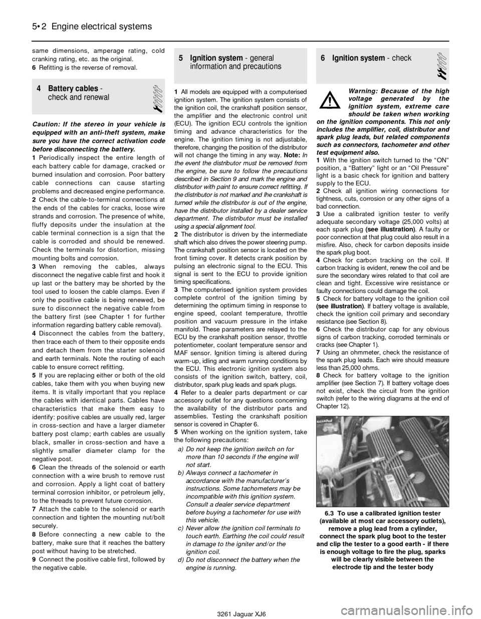
3Use a calibrated ignition tester to verify
adequate secondary voltage (25,000 volts) at
each spark plug (see illustration). A faulty or
poor connection at that plug could also result in a
misfire. Also, check for carbon deposits inside
the spark plug boot.
4Check for carbon tracking on the coil. If
carbon tracking is evident, renew the coil and be
sure the secondary wires related to that coil are
clean and tight. Excessive wire resistance or
faulty connections could damage the coil.
5Check for battery voltage to the ignition coil
(see illustration). If battery voltage is available,
check the ignition coil primary and secondary
resistance (see Section 8).
6Check the distributor cap for any obvious
signs of carbon tracking, corroded terminals or
cracks (see Chapter 1).
7Using an ohmmeter, check the resistance of
the spark plug leads. Each wire should measure
less than 25,000 ohms.
8Check for battery voltage to the ignition
amplifier (see Section 7). If battery voltage does
not exist, check the circuit from the ignition
switch (refer to the wiring diagrams at the end of
Chapter 12).
5•2 Engine electrical systems
6.3 To use a calibrated ignition tester
(available at most car accessory outlets),
remove a plug lead from a cylinder,
connect the spark plug boot to the tester
and clip the tester to a good earth - if there
is enough voltage to fire the plug, sparks
will be clearly visible between the
electrode tip and the tester body
3261 Jaguar XJ6
Page 105 of 227
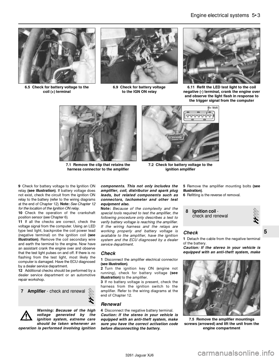
9Check for battery voltage to the Ignition ON
relay (see illustration). If battery voltage does
not exist, check the circuit from the ignition ON
relay to the battery (refer to the wiring diagrams
at the end of Chapter 12). Note:See Chapter 12
for the location of the Ignition ON relay.
10Check the operation of the crankshaft
position sensor (see Chapter 6).
11If all the checks are correct, check the
voltage signal from the computer. Using an LED
type test light, backprobe the coil power lead
(negative terminal) on the ignition coil (see
illustration). Remove the coil secondary wire
and earth the terminal to the engine. Now have
an assistant crank the engine over and observe
that the test light pulses on and off. If there is no
flashing from the test light, most likely the
computer is damaged. Have the ECU diagnosed
by a dealer service department.
12Additional checks should be performed by a
dealer service department or an automotive
repair workshop.
7 Amplifier- check and renewal
2
Warning: Because of the high
voltage generated by the
ignition system, extreme care
should be taken whenever an
operation is performed involving ignitioncomponents. This not only includes the
amplifier, coil, distributor and spark plug
leads, but related components such as
connectors, tachometer and other test
equipment also.
Note:Because of the complexity and the
special tools required to test the amplifier, the
following procedure only describes a test to
verify battery voltage is reaching the amplifier.
If the wiring harness and the relays are
working properly and battery voltage is
available to the amplifier, have the ignition
system and the ECU diagnosed by a dealer
service department.
Check
1Disconnect the amplifier electrical connector
(see illustration).
2Turn the ignition key ON (engine not
running), check for battery voltage (see
illustration) to the amplifier.
3If no battery voltage is present, check the
harness from the ignition switch to the
amplifier. Refer to the wiring diagrams at the
end of Chapter 12.
Renewal
4Disconnect the negative battery terminal.
Caution: If the stereo in your vehicle is
equipped with an anti-theft system, make
sure you have the correct activation code
before disconnecting the battery.5Remove the amplifier mounting bolts (see
illustration).
6Refitting is the reverse of removal.
8 Ignition coil-
check and renewal
2
Check
1Detach the cable from the negative terminal
of the battery.
Caution: If the stereo in your vehicle is
equipped with an anti-theft system, make
Engine electrical systems 5•3
5
6.5 Check for battery voltage to the
coil (+) terminal6.9 Check for battery voltage
to the IGN ON relay6.11 Refit the LED test light to the coil
negative (-) terminal, crank the engine over
and observe the light flash in response to
the trigger signal from the computer
7.1 Remove the clip that retains the
harness connector to the amplifier7.2 Check for battery voltage to the
ignition amplifier
7.5 Remove the amplifier mountings
screws (arrowed) and lift the unit from the
engine compartment
3261 Jaguar XJ6
Page 113 of 227
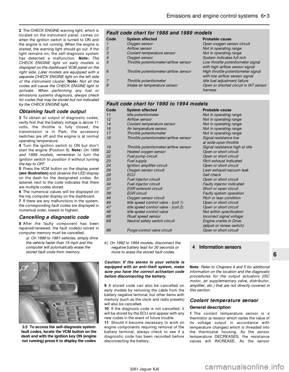
2The CHECK ENGINE warning light, which is
located on the instrument panel, comes on
when the ignition switch is turned to ON and
the engine is not running. When the engine is
started, the warning light should go out. If the
light remains on, the self-diagnosis system
has detected a malfunction. Note: The
CHECK ENGINE light on early models is
displayed on the dashboard VCM panel on the
right side. Later models are equipped with a
separate CHECK ENGINE light on the left side
of the instrument cluster.Note:Not all the
codes will cause the CHECK ENGINE light to
activate. When performing any fuel or
emissions systems diagnosis, always check
for codes that may be stored but not indicated
by the CHECK ENGINE light.
Obtaining fault code output
3To obtain an output of diagnostic codes,
verify first that the battery voltage is above 11
volts, the throttle is fully closed, the
transmission is in Park, the accessory
switches are off and the engine is at normal
operating temperature.
4Turn the ignition switch to ON but don’t
start the engine (Position II). Note:On 1988
and 1989 models, remember to turn the
ignition switch to position II without turning
the key to OFF.
5Press the VCM button on the display panel
(see illustration)and observe the LED display
on the dash for the designated codes. An
asterisk next to the code indicates that there
are multiple codes stored.
6The numerical values will be displayed on
the trip computer display on the dashboard.
7If there are any malfunctions in the system,
the corresponding fault codes are displayed in
numerical order, lowest to highest.
Cancelling a diagnostic code
8After the faulty component has been
repaired/renewed, the fault code(s) stored in
computer memory must be cancelled.
a) On 1988 to 1991 vehicles, simply drive
the vehicle faster than 19 mph and the
computer will automatically erase the
stored fault code from memory.b) On 1992 to 1994 models, disconnect the
negative battery lead for 30 seconds or
more to erase the stored fault codes.
Caution: If the stereo in your vehicle is
equipped with an anti-theft system, make
sure you have the correct activation code
before disconnecting the battery.
9A stored code can also be cancelled on
early models by removing the cable from the
battery negative terminal, but other items with
memory (such as the clock and radio presets)
will also be cancelled.
10If the diagnosis code is not cancelled, it
will be stored by the ECU and appear with any
new codes in the event of future trouble.
11Should it become necessary to work on
engine components requiring removal of the
battery terminal, always check to see if a
diagnostic code has been recorded before
disconnecting the battery.
4 Information sensors
Note: Refer to Chapters 4 and 5 for additional
information on the location and the diagnostic
procedures for the output actuators (ISC
motor, air supplementary valve, distributor,
amplifier, etc.) that are not directly covered in
this section.
Coolant temperature sensor
General description
1The coolant temperature sensor is a
thermistor (a resistor which varies the value of
its voltage output in accordance with
temperature changes) which is threaded into
the thermostat housing. As the sensor
temperature DECREASES, the resistance
values will INCREASE. As the sensor
Emissions and engine control systems 6•3
6
3.5 To access the self-diagnosis system
fault codes, locate the VCM button on the
dash and with the ignition key ON (engine
not running) press it to display the codes
3261 Jaguar XJ6
Fault code chart for 1988 and 1989 models
Code System affected Probable cause
1 Oxygen sensor Open oxygen sensor circuit
2 Airflow sensor Not in operating range
3 Coolant temperature sensor Not in operating range
4 Oxygen sensor System indicates full rich
5 Throttle potentiometer/airflow sensor Low throttle potentiometer signal
with high airflow sensor signal
6 Throttle potentiometer/airflow sensor High throttle potentiometer signal
with low airflow sensor signal
7 Throttle potentiometer Idle fuel adjustment failure
8 Intake air temperature sensor Open or shorted circuit in IAT sensor
harness
Fault code chart for 1990 to 1994 models
Code System affected Probable cause
11 Idle potentiometer Not in operating range
12 Airflow sensor Not in operating range
14 Coolant temperature sensor Not in operating range
16 Air temperature sensor Not in operating range
17 Throttle potentiometer Not in operating range
18 Throttle potentiometer/airflow sensor Signal resistance low
at wide open throttle
19 Throttle potentiometer/airflow sensor Signal resistance high at idle
22 Heated oxygen sensor Open or short circuit
22 Fuel pump circuit Open or short circuit
23 Fuel supply Rich exhaust Indicated
24 Ignition amplifier circuit Open or short circuit
26 Oxygen sensor circuit Lean exhaust/vacuum leak
29 ECU Self check
33 Fuel injector circuit Open or short circuit
34 Fuel injector circuit Faulty injector indicated
37 EGR solenoid circuit Short or open circuit
39 EGR circuit Faulty system operation
44 Oxygen sensor circuit Rich or lean condition
46 Idle speed control valve - (coil 1) Open or short circuit
47 Idle speed control valve - (coil 2) Open or short circuit
48 Idle speed control valve Not within specification
68 Road speed sensor Incorrect signal voltage
69 Neutral safety switch circuit Engine cranks in Drive
(adjust or renew switch)
89 Purge control valve circuit Open or short circuit
Page 147 of 227
and installed on a new or rebuilt pump. (This
procedure requires special tools, and the
height of the driven coupling on the shaft
must be set with a depth gauge.)
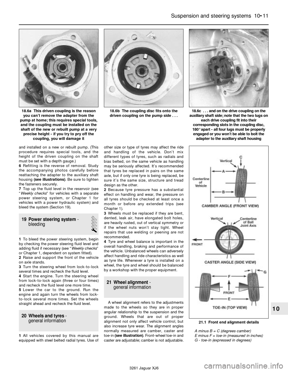
6Refitting is the reverse of removal. Study
the accompanying photos carefully before
reattaching the adapter to the auxiliary shaft
housing (see illustrations). Be sure to tighten
the fasteners securely.
7Top up the fluid level in the reservoir (see
“Weekly checks” for vehicles with a separate
power steering system, or Chapter 1 for
vehicles with a power hydraulic system) and
bleed the system (Section 19).
19 Power steering system-
bleeding
1
1To bleed the power steering system, begin
by checking the power steering fluid level and
adding fluid if necessary (see “Weekly checks”
or Chapter 1, dependent on system fitted).
2Raise and support the front of the vehicle
on axle stands.
3Turn the steering wheel from lock-to-lock
several times and recheck the fluid level.
4Start the engine. Turn the steering wheel
from lock-to-lock again (three or four times)
and recheck the fluid level one more time.
5Lower the car to the ground. Run the
engine and again turn the wheels from lock-
to-lock several more times. Set the wheels
straight ahead and recheck the fluid level.
20 Wheels and tyres-
general information
1All vehicles covered by this manual are
equipped with steel belted radial tyres. Use ofother size or type of tyres may affect the ride
and handling of the vehicle. Don’t mix
different types of tyres, such as radials and
bias belted, on the same vehicle as handling
may be seriously affected. It’s recommended
that tyres be replaced in pairs on the same
axle, but if only one tyre is being replaced, be
sure it’s the same size, structure and tread
design as the other.
2Because tyre pressure has a substantial
effect on handling and wear, the pressure on
all tyres should be checked at least once a
month or before any extended trips (see
Chapter 1).
3Wheels must be replaced if they are bent,
dented, leak air, have elongated bolt holes,
are heavily rusted, out of vertical symmetry or
if the wheel nuts won’t stay tight. Wheel
repairs that use welding or peening are not
recommended.
4Tyre and wheel balance is important in the
overall handling, braking and performance of
the vehicle. Unbalanced wheels can adversely
affect handling and ride characteristics as well
as tyre life. Whenever a tyre is installed on a
wheel, the tyre and wheel should be balanced
by a workshop with the proper equipment.
21 Wheel alignment-
general information
A wheel alignment refers to the adjustments
made to the wheels so they are in proper
angular relationship to the suspension and the
ground. Wheels that are out of proper
alignment not only affect vehicle control, but
also increase tyre wear. The alignment angles
normally measured are camber, caster and
toe-in (see illustration). Front-wheel toe-in and
caster are adjustable; camber is not adjustable.
Suspension and steering systems 10•11
10
3261 Jaguar XJ6 18.6a This driven coupling is the reason
you can’t remove the adapter from the
pump at home; this requires special tools,
and the coupling must be installed on the
shaft of the new or rebuilt pump at a very
precise height - if you try to pry off the
coupling, you will damage it
18.6b The coupling disc fits onto the
driven coupling on the pump side . . .18.6c . . . and on the drive coupling on the
auxiliary shaft side; note that the two lugs on
each drive coupling fit into their
corresponding slots in the coupling disc,
180° apart - all four lugs must be properly
engaged or you won’t be able to bolt the
adapter to the auxiliary shaft housing
21.1 Front end alignment details
A minus B = C (degrees camber)
E minus F = toe-in (measured in inches)
G - toe-in (expressed in degrees)
Page 153 of 227
7Attach a piece of thin wire or string to the
end of the cables to help aid the refitting
process.
8Working in the engine compartment, pull
the cables and grommet out of the bulkhead
until you can see the wire or string. Ensure
that the new cable has a grommet attached
then remove the old cable from the wire or
string and replace it with the new cable.
9Working from passenger compartment pull
the wire or string back through the bulkhead.
10Refitting is the reverse of removal.Note:
Push on the grommet with your fingers from
the engine compartment to seat the grommet
in the bulkhead.
12 Radiator grille-
removal and refitting
1
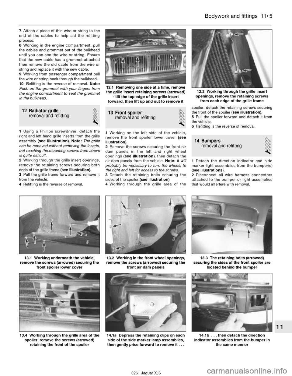
1Using a Phillips screwdriver, detach the
right and left hand grille inserts from the grille
assembly (see illustration).Note: The grille
can be removed without removing the inserts,
but reaching the mounting screws from above
is quite difficult.
2Working through the grille insert openings,
remove the retaining screws securing both
ends of the grille frame (see illustration).
3Pull the grille frame forward and remove it
from the vehicle.
4Refitting is the reverse of removal.
13 Front spoiler-
removal and refitting
1
1Working on the left side of the vehicle,
remove the front spoiler lower cover (see
illustration).
2Remove the screws securing the front air
dam panels in the left and right wheel
openings (see illustration), then detach the
air dam panels from the vehicle. Note:It will
probably be necessary to turn the wheels to
the right and left for access to the screws.
3Detach the retaining bolts securing the
sides of the spoiler (see illustration).
4Working through the grille area of thespoiler, detach the retaining screws securing
the front of the spoiler (see illustration).
5Pull the spoiler forward and detach it from
the vehicle.
6Refitting is the reverse of removal.
14 Bumpers-
removal and refitting
1
1Detach the direction indicator and side
marker light assemblies from the bumper(s)
(see illustrations).
2Disconnect all wire harness connectors
attached to the bumper or light assemblies
that would interfere with removal.
Bodywork and fittings 11•5
11
12.1 Removing one side at a time, remove
the grille insert retaining screws (arrowed)
- tilt the top edge of the grille insert
forward, then lift up and out to remove it12.2 Working through the grille insert
openings, remove the retaining screws
from each edge of the grille frame
13.4 Working through the grille area of the
spoiler, remove the screws (arrowed)
retaining the front of the spoiler14.1a Depress the retaining clips on each
side of the side marker lamp assemblies,
then gently prise forward to remove it . . .14.1b . . . then detach the direction
indicator assemblies from the bumper in
the same manner
13.1 Working underneath the vehicle,
remove the screws (arrowed) securing the
front spoiler lower cover13.2 Working in the front wheel openings,
remove the screws (arrowed) securing the
front air dam panels13.3 The retaining bolts (arrowed)
securing the sides of the front spoiler are
located behind the bumper
3261 Jaguar XJ6
Page 214 of 227
3261 Jaguar XJ6
Fault findingREF•13
1 Engine
Engine will not rotate when attempting to start
m mBattery terminal connections loose or corroded (Chapter 1).
m mBattery discharged or faulty (Chapter 1).
m mDamaged left rear window harness shorting against glass rail
inside door, causing battery to drain (Chapter 12).
m mAutomatic transmission not completely engaged in Park
(Chapter 7).
m mBroken, loose or disconnected wiring in the starting circuit
(Chapters 5 and 12).
m mStarter motor pinion jammed in flywheel ring gear (Chapter 5).
m mStarter solenoid faulty (Chapter 5).
m mStarter motor faulty (Chapter 5).
m mIgnition switch faulty (Chapter 12).
m mStarter pinion or flywheel teeth worn or broken (Chapter 5).
m mInternal engine problem (Chapter 2B).
m mInertia switch activated (Chapter 12).
m mStarter relay defective (Chapter 5).
Engine rotates but will not start
m
mFuel tank empty.
m mBattery discharged (engine rotates slowly) (Chapter 5).
m mBattery terminal connections loose or corroded (Chapter 1).
m mLeaking fuel injector(s), faulty fuel pump, pressure regulator, etc.
(Chapter 4).
m mFuel not reaching fuel injection system (Chapter 4).
m mIgnition components damp or damaged (Chapter 5).
m mFuel injector stuck open (Chapter 4).
m mWorn, faulty or incorrectly gapped spark plugs (Chapter 1).
m mBroken, loose or disconnected wiring in the starting circuit
(Chapter 5).
m mLoose distributor is changing ignition timing (Chapter 1).
m mBroken, loose or disconnected wires at the ignition coil or faulty
coil (Chapter 5).
m m1988 and 1989 models may have electrical connector damage
between the fuel pump relay and the fuel pump (Chapter 12).
m mCoolant temperature sensor shorting on bonnet liner (Chapter 11).
m mDefective Mass Airflow (MAF) sensor (Chapter 6).
Engine hard to start when cold
m
mBattery discharged or low (Chapter 1).
m mFuel system malfunctioning (Chapter 4).
m mInjector(s) leaking (Chapter 4).
m mDistributor rotor carbon tracked (Chapter 5).
m mWater enters the air cleaner housing near the left front wheel arch
(Chapter 4).
Engine hard to start when hot
m mAir filter clogged (Chapter 1).
m mFuel not reaching the fuel injection system (Chapter 4).
m mCorroded battery connections, especially ground (Chapter 1).
m mFuel vaporises at fuel pump inlet. Refit dual fuel pumps
(Chapter 4).
m mFuel vapours from charcoal canister enter intake during idle and
cause idling, stalling and starting problems (Chapter 6).
Starter motor noisy or excessively rough in
engagement
m mPinion or flywheel gear teeth worn or broken (Chapter 5).
m mStarter motor mounting bolts loose or missing (Chapter 5).
Engine starts but stops immediately
m
mLoose or faulty electrical connections at distributor, coil or
alternator (Chapter 5).
m mInsufficient fuel reaching the fuel injector(s) (Chapters 1 and 4).
m mDamaged fuel injection system speed sensors (Chapter 5).
m mFaulty fuel injection relays (Chapter 5).
m mLeaking threaded adapter on the EGR valve - where fitted
(Chapter 6)
Oil puddle under engine
m mSump gasket and/or sump drain bolt seal leaking (Chapter 2).
m mOil pressure sending unit leaking (Chapter 2).
m mValve cover gaskets leaking (Chapter 2).
m mEngine oil seals leaking (Chapter 2).
m mCylinder head rear plate gasket leaking (Chapter 2).
m mAlternator mounting bolt threads leaking oil (Chapter 5).
m mOil cooler or oil cooler lines leaking (Chapter 3).
Engine misses while idling or idles erratically
m
mVacuum leakage (Chapter 2).
m mAir filter clogged (Chapter 1).
m mFuel pump not delivering sufficient fuel to the fuel injection system
(Chapter 4).
m mLeaking head gasket (Chapter 2).
m mTiming belt/chain and/or sprockets worn (Chapter 2).
m mCamshaft lobes worn (Chapter 2).
m mEGR valve stuck open - where fitted (Chapter 6).
Engine misses at idle speed
m
mSpark plugs worn or not gapped properly (Chapter 1).
m mFaulty spark plug leads (Chapter 1).
m mVacuum leaks (Chapter 1).
m mIncorrect ignition timing (Chapter 5).
m mUneven or low compression (Chapter 2).
m mRestricted EGR vacuum hose - where fitted (Chapter 6).
Engine misses throughout driving speed range
m
mFuel filter clogged and/or impurities in the fuel system (Chapter 1).
m mLow fuel output at the injectors (Chapter 4).
m mFaulty or incorrectly gapped spark plugs (Chapter 1).
m mIncorrect ignition timing (Chapter 5).
m mCracked distributor cap, disconnected distributor wires or
damaged distributor components (Chapter 1).
m mLeaking spark plug leads (Chapter 1).
m mFaulty emission system components (Chapter 6).
m mLow or uneven cylinder compression pressures (Chapter 2).
m mWeak or faulty ignition system (Chapter 5).
m mVacuum leak in fuel injection system, intake manifold or vacuum
hoses (Chapter 4).
m mCrankshaft sensor teeth damaged or missing (see Chapter 12).
m mDistributor installed incorrectly (see Chapter 5)
Engine stumbles on acceleration
m
mSpark plugs fouled (Chapter 1).
m mFuel injection system malfunctioning (Chapter 4).
m mFuel filter clogged (Chapters 1 and 4).
m mIncorrect ignition timing (Chapter 5).
m mIntake manifold air leak (Chapter 4).
m mCollapsed or damaged fuel tank caused by blocked EVAP system
- where fitted (see Chapter 6).
Page 221 of 227
3261 Jaguar XJ6
REF•20Glossary of technical terms
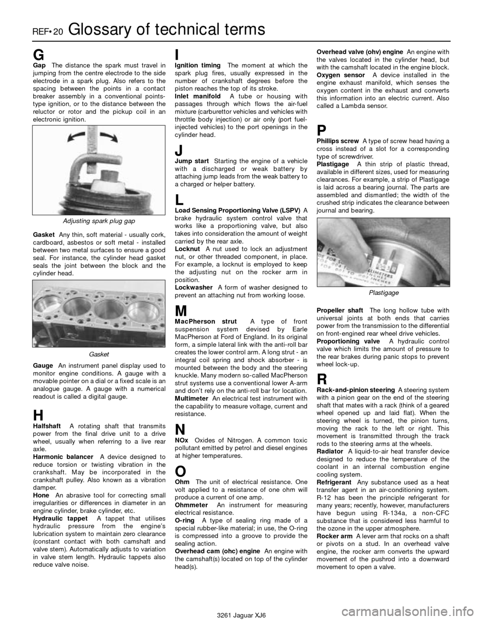
GGapThe distance the spark must travel in
jumping from the centre electrode to the side
electrode in a spark plug. Also refers to the
spacing between the points in a contact
breaker assembly in a conventional points-
type ignition, or to the distance between the
reluctor or rotor and the pickup coil in an
electronic ignition.
GasketAny thin, soft material - usually cork,
cardboard, asbestos or soft metal - installed
between two metal surfaces to ensure a good
seal. For instance, the cylinder head gasket
seals the joint between the block and the
cylinder head.
GaugeAn instrument panel display used to
monitor engine conditions. A gauge with a
movable pointer on a dial or a fixed scale is an
analogue gauge. A gauge with a numerical
readout is called a digital gauge.
HHalfshaftA rotating shaft that transmits
power from the final drive unit to a drive
wheel, usually when referring to a live rear
axle.
Harmonic balancerA device designed to
reduce torsion or twisting vibration in the
crankshaft. May be incorporated in the
crankshaft pulley. Also known as a vibration
damper.
HoneAn abrasive tool for correcting small
irregularities or differences in diameter in an
engine cylinder, brake cylinder, etc.
Hydraulic tappetA tappet that utilises
hydraulic pressure from the engine’s
lubrication system to maintain zero clearance
(constant contact with both camshaft and
valve stem). Automatically adjusts to variation
in valve stem length. Hydraulic tappets also
reduce valve noise.
IIgnition timingThe moment at which the
spark plug fires, usually expressed in the
number of crankshaft degrees before the
piston reaches the top of its stroke.
Inlet manifoldA tube or housing with
passages through which flows the air-fuel
mixture (carburettor vehicles and vehicles with
throttle body injection) or air only (port fuel-
injected vehicles) to the port openings in the
cylinder head.
JJump startStarting the engine of a vehicle
with a discharged or weak battery by
attaching jump leads from the weak battery to
a charged or helper battery.
LLoad Sensing Proportioning Valve (LSPV)A
brake hydraulic system control valve that
works like a proportioning valve, but also
takes into consideration the amount of weight
carried by the rear axle.
LocknutA nut used to lock an adjustment
nut, or other threaded component, in place.
For example, a locknut is employed to keep
the adjusting nut on the rocker arm in
position.
LockwasherA form of washer designed to
prevent an attaching nut from working loose.
MMacPherson strutA type of front
suspension system devised by Earle
MacPherson at Ford of England. In its original
form, a simple lateral link with the anti-roll bar
creates the lower control arm. A long strut - an
integral coil spring and shock absorber - is
mounted between the body and the steering
knuckle. Many modern so-called MacPherson
strut systems use a conventional lower A-arm
and don’t rely on the anti-roll bar for location.
MultimeterAn electrical test instrument with
the capability to measure voltage, current and
resistance.
NNOxOxides of Nitrogen. A common toxic
pollutant emitted by petrol and diesel engines
at higher temperatures.
OOhmThe unit of electrical resistance. One
volt applied to a resistance of one ohm will
produce a current of one amp.
OhmmeterAn instrument for measuring
electrical resistance.
O-ringA type of sealing ring made of a
special rubber-like material; in use, the O-ring
is compressed into a groove to provide the
sealing action.
Overhead cam (ohc) engineAn engine with
the camshaft(s) located on top of the cylinder
head(s).Overhead valve (ohv) engineAn engine with
the valves located in the cylinder head, but
with the camshaft located in the engine block.
Oxygen sensorA device installed in the
engine exhaust manifold, which senses the
oxygen content in the exhaust and converts
this information into an electric current. Also
called a Lambda sensor.
PPhillips screwA type of screw head having a
cross instead of a slot for a corresponding
type of screwdriver.
PlastigageA thin strip of plastic thread,
available in different sizes, used for measuring
clearances. For example, a strip of Plastigage
is laid across a bearing journal. The parts are
assembled and dismantled; the width of the
crushed strip indicates the clearance between
journal and bearing.
Propeller shaftThe long hollow tube with
universal joints at both ends that carries
power from the transmission to the differential
on front-engined rear wheel drive vehicles.
Proportioning valveA hydraulic control
valve which limits the amount of pressure to
the rear brakes during panic stops to prevent
wheel lock-up.
RRack-and-pinion steeringA steering system
with a pinion gear on the end of the steering
shaft that mates with a rack (think of a geared
wheel opened up and laid flat). When the
steering wheel is turned, the pinion turns,
moving the rack to the left or right. This
movement is transmitted through the track
rods to the steering arms at the wheels.
RadiatorA liquid-to-air heat transfer device
designed to reduce the temperature of the
coolant in an internal combustion engine
cooling system.
RefrigerantAny substance used as a heat
transfer agent in an air-conditioning system.
R-12 has been the principle refrigerant for
many years; recently, however, manufacturers
have begun using R-134a, a non-CFC
substance that is considered less harmful to
the ozone in the upper atmosphere.
Rocker armA lever arm that rocks on a shaft
or pivots on a stud. In an overhead valve
engine, the rocker arm converts the upward
movement of the pushrod into a downward
movement to open a valve.
Adjusting spark plug gap
Plastigage
Gasket