ECO mode JAGUAR XJ6 1997 2.G Service Manual
[x] Cancel search | Manufacturer: JAGUAR, Model Year: 1997, Model line: XJ6, Model: JAGUAR XJ6 1997 2.GPages: 227, PDF Size: 7.2 MB
Page 128 of 227
Refitting
8Place the disc on the hub and refit the disc
retaining screw. Tighten the screw securely.
9Refit the caliper mounting bracket, using a
new safety wire on the mounting bolts.
10Refit the brake pads and caliper (see
Section 3). Tighten all fasteners to the torque
listed in this Chapter’s Specifications.
11Refit the wheel and wheel nuts, then lower
the vehicle to the ground. Tighten the wheel
nuts to the specified torque (see Chapter 1
Specifications). Depress the brake pedal a
few times to bring the brake pads into contact
with the disc.
12Adjust the handbrake shoes, if necessary.
13Check the operation of the brakes
carefully, if possible before driving the vehicle
on public roads.
6 Master cylinder- removal,
overhaul and refitting
3
Note:Although master cylinder parts and
rebuild kits are available for most models, we
recommend replacing the master cylinder with
a new or remanufactured unit, if possible.
Removal
1The master cylinder is connected to the
brake servo, which is attached to the pedal
box, in front of the bulkhead on the driver’s
side of the engine compartment.
2Remove as much fluid as you can from the
reservoir with a syringe.
3Place rags under the line fittings and
prepare caps or plastic bags to cover the
ends of the lines once they are disconnected.
Caution: Brake fluid will damage paint.
Cover all body parts and be careful not to
spill fluid during this procedure.
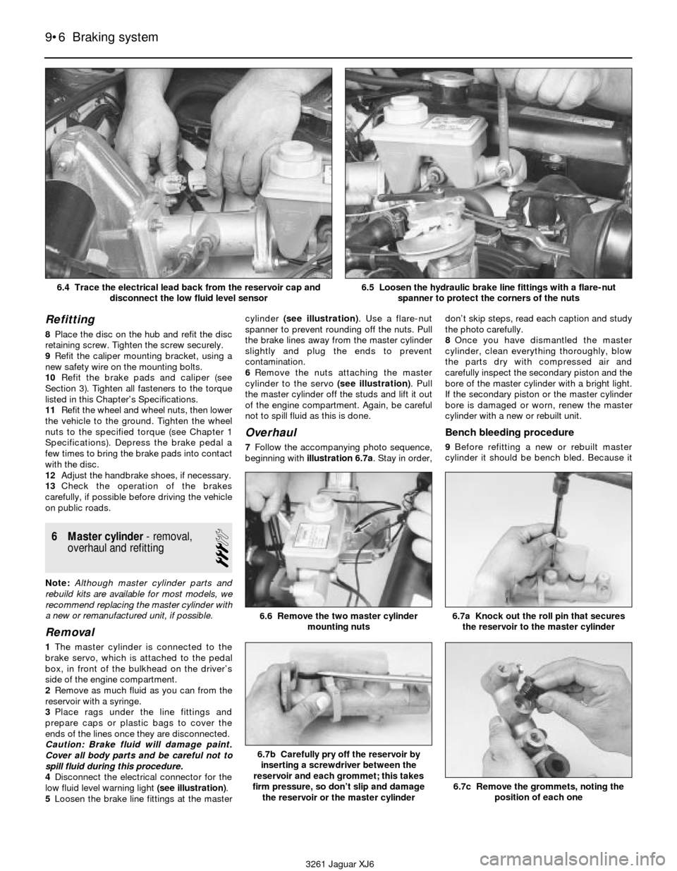
4Disconnect the electrical connector for the
low fluid level warning light (see illustration).
5Loosen the brake line fittings at the mastercylinder (see illustration). Use a flare-nut
spanner to prevent rounding off the nuts. Pull
the brake lines away from the master cylinder
slightly and plug the ends to prevent
contamination.
6Remove the nuts attaching the master
cylinder to the servo (see illustration). Pull
the master cylinder off the studs and lift it out
of the engine compartment. Again, be careful
not to spill fluid as this is done.
Overhaul
7Follow the accompanying photo sequence,
beginning with illustration 6.7a. Stay in order,don’t skip steps, read each caption and study
the photo carefully.
8Once you have dismantled the master
cylinder, clean everything thoroughly, blow
the parts dry with compressed air and
carefully inspect the secondary piston and the
bore of the master cylinder with a bright light.
If the secondary piston or the master cylinder
bore is damaged or worn, renew the master
cylinder with a new or rebuilt unit.
Bench bleeding procedure
9Before refitting a new or rebuilt master
cylinder it should be bench bled. Because it
9•6 Braking system
6.7a Knock out the roll pin that secures
the reservoir to the master cylinder
6.7b Carefully pry off the reservoir by
inserting a screwdriver between the
reservoir and each grommet; this takes
firm pressure, so don’t slip and damage
the reservoir or the master cylinder
6.7c Remove the grommets, noting the
position of each one
6.6 Remove the two master cylinder
mounting nuts
3261 Jaguar XJ6 6.4 Trace the electrical lead back from the reservoir cap and
disconnect the low fluid level sensor
6.5 Loosen the hydraulic brake line fittings with a flare-nut
spanner to protect the corners of the nuts
Page 131 of 227
being drawn back into the master cylinder.
Wait several seconds for brake fluid to be
drawn from the reservoir into the piston bore,
then depress the piston again, removing your
finger as brake fluid is expelled. Be sure to put
your finger back over the hole each time
before releasing the piston, and when the
bleeding procedure is complete for that outlet,
renew the plug and snug it up before going on
to the other port.
Refitting
16Refit the master cylinder over the studs on
the brake servo and tighten the mounting nuts
only finger tight at this time.
17Thread the brake line fittings into the
master cylinder. Since the master cylinder is
still a bit loose, it can be moved slightly to
allow the fitting threads to start easily. Do not
strip the threads as the fittings are tightened.
18Tighten the brake fittings securely and the
mounting nuts to the torque listed in this
Chapter’s Specifications.
19Fill the master cylinder reservoir with fluid,
then bleed the master cylinder and the brake
system (see Section 9).
20To bleed the master cylinder on the
vehicle, have an assistant pump the brake
pedal several times and then hold the pedal to
the floor. Loosen the fitting nut to allow air and
fluid to escape, then tighten the nut. Repeat
this procedure on both fittings until the fluid is
clear of air bubbles. Test the operation of the
brake system carefully before placing the
vehicle into service.
7 Brake servo-
general information,
removal and refitting
2
General information
1A hydraulic brake servo system assists
braking when the brake pedal is depressed.
The booster unit, located between the brake
pedal box and the master cylinder, is operated
by hydraulic pressure generated by an engine-
driven pump (on early models) or by an electric
pump (on later models). When the engine isrunning, the pump supplies hydraulic pressure
to an accumulator. The accumulator stores and
regulates the pressure to the hydraulic brake
servo. When you depress the brake pedal, the
pressure in the booster helps actuate the
master cylinder, reducing pedal effort.
2The hydraulic brake servo isn’t rebuildable;
if it fails, it must be replaced. Basic operation
can be checked (see Chapter 1, Section 15),
but in-depth testing of the system requires
special tools, so diagnosis is beyond the
scope of the home mechanic. If the system
fails, take it to a dealer service department or
other qualified repair workshop for repairs.
However, if the unit must be replaced, you
can do it yourself as follows.
Removal and refitting
3With the engine off, discharge the hydraulic
accumulator by depressing the brake pedal
several times until it feels hard to depress.
4Remove the master cylinder (see Section 6).
5Clean the area around the return and
supply tube nuts, then disconnect them with a
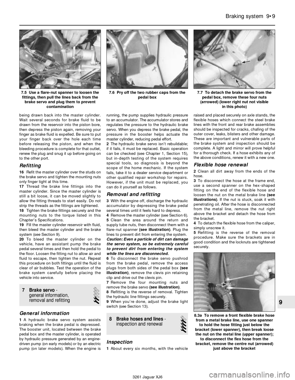
flare-nut spanner (see illustration). Plug the
lines to prevent dirt from entering the system.
Caution: Even a particle of dirt can damage
the servo system, so be extremely careful
to prevent dirt from entering the system
while the lines are disconnected.
6To disconnect the brake servo pushrod
from the brake pedal, remove the access
plugs from both sides of the pedal box (see
illustration), remove the clevis pin retaining
clip and drive out the clevis pin.
7Remove the four mounting nuts and
remove the brake servo (see illustration).
8Refitting is the reverse of removal. Tighten
the hydraulic line fittings securely.
9When you’re done, adjust the brake light
switch (see Section 13).
8 Brake hoses and lines-
inspection and renewal
4
Inspection
1About every six months, with the vehicleraised and placed securely on axle stands, the
flexible hoses which connect the steel brake
lines with the front and rear brake assemblies
should be inspected for cracks, chafing of the
outer cover, leaks, blisters and other damage.
These are important and vulnerable parts of
the brake system and inspection should be
complete. A light and mirror will prove helpful
for a thorough check. If a hose exhibits any of
the above conditions, renew it with a new one.
Flexible hose renewal
2Clean all dirt away from the ends of the
hose.
3To disconnect the hose at the frame end,
use a second spanner on the hex-shaped
fitting on the end of the flexible hose and
loosen the nut on the metal brake line (see
illustrations). If the nut is stuck, soak it with
penetrating oil. After the hose is disconnected
from the metal line, remove the nut right
above the bracket and detach the hose from
the bracket.
4To detach the flexible hose from the caliper,
simply unscrew it.
5Refitting is the reverse of the removal
procedure. Make sure the brackets are in
good condition and the locknuts are tightened
securely.
Braking system 9•9
9
7.5 Use a flare-nut spanner to loosen the
fittings, then pull the lines back from the
brake servo and plug them to prevent
contamination7.6 Pry off the two rubber caps from the
pedal box7.7 To detach the brake servo from the
pedal box, remove these four nuts
(arrowed) (lower right nut not visible
in this photo)
8.3a To remove a front flexible brake hose
from a metal brake line, use one spanner
to hold the hose fitting just below the
bracket (lower spanner), then break loose
the nut on the metal line (upper spanner);
to disconnect the flex hose from the
bracket, remove the centre nut (arrowed)
just above the bracket
3261 Jaguar XJ6
Page 146 of 227

17 Steering gear-
removal and refitting
3
Warning: On models with an
airbag, do not apply excessive
force or severe shock to the
steering column shaft, or
accidental deployment of the airbag could
occur.
1Using a large syringe or hand pump, empty
the power steering fluid reservoir.
2Loosen the wheel nuts, raise the vehicle
and support it securely on axle stands.
Remove the wheels.
3Mark the relationship of the steering shaft
U-joint to the steering gear pinion shaft (see
illustration)to ensure proper alignment when
they’re reassembled. Remove the nut and bolt
that clamp the U-joint to the pinion shaft.
4Disconnect the power steering pressure
and return lines from the steering gear. Place
a container under the lines to catch spilledfluid. Plug the lines to prevent excessive fluid
loss and contamination. Discard the sealing
washers (new ones should be used when
reassembling).
5Disconnect the tie-rod ends from the
steering knuckle arms (see Section 17).
6Remove the nuts and bolts from the steering
gear mounting brackets (see illustration).
7Remove the steering gear assembly,
detaching the U-joint as you lower it. Don’t
damage the steering gear dust boots.
8Refitting is the reverse of removal. Ensure the
marks you made on the U-joint and the pinion
shaft are aligned before you tighten the U-joint
clamp bolt and nut. Tighten the mounting bolts,
the tie-rod end nuts and the U-joint shaft
clamping bolts to the specified torque.
9After lowering the vehicle, fill the reservoir
with the recommended fluid (see Chapter 1).
10Bleed the power steering system (see
Section 19).
11Have the front wheels aligned by a dealer
service department or alignment workshop
after reassembly.
18 Power steering pump-
removal and refitting
3
1Raise the vehicle and support it securely on
axle stands. Remove the engine under-cover.
2Loosen the hose clamp and disconnect the
fluid return hose from the top of the pump
(see illustration)and drain the power steering
fluid from the reservoir into a clean container.
Unscrew the pressure line fitting from the
back of the pump. Plug the return hose and
the pressure line to prevent fluid from leaking
and to protect the power steering system
from contamination.
3Remove the bolts (see illustration)that
attach the power steering pump adapter to
the auxiliary shaft housing.
4Remove the power steering pump and
adapter.
5Take the power steering pump and adapter
to a Jaguar dealer service department and
have the adapter removed from the old pump
10•10 Suspension and steering systems
18.2 Disconnect the steering fluid return hose from the upper
pipe (arrowed) and disconnect the pressure line
from the back of the pump18.3 To detach the pump adapter from the auxiliary shaft
housing, remove these bolts
3261 Jaguar XJ6 17.3 Mark the relationship of the steering shaft U-joint to the
steering gear pinion shaft, then unscrew the pressure and return
line fittings (arrowed) - plug the lines to prevent contamination
from entering the system
17.6 To detach the steering gear from the vehicle, remove these
nuts and bolts (arrowed) from the mounting brackets (right
bracket shown, left bracket similar)
Page 160 of 227
selector towards the rear of the vehicle. Pull
up on the rear half of the radio trim bezel while
gently detaching the clips securing the front,
then remove the bezel from the vehicle.
6Remove the radio and heater control
assembly (see Chapter 12).
7Remove the dashboard centre trim panel
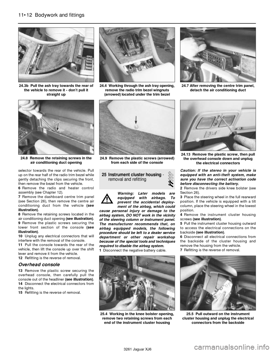
(see Section 26), then remove the centre air
conditioning duct from the vehicle (see
illustration).
8Remove the retaining screws located in the
air conditioning duct opening (see illustration).
9Remove the plastic screws securing the
lower front section of the console (see
illustration).
10Unplug any electrical connectors that will
interfere with the removal of the console.
11Pull the console towards the rear of the
vehicle, then lift the console up over the shift
lever and remove it from the vehicle.
12Refitting is the reverse of removal.
Overhead console
13Remove the plastic screw securing the
overhead console, then carefully pull the
console out of the headliner (see illustration).
14Disconnect the electrical connectors from
the lights.
15Refitting is the reverse of removal.
25 Instrument cluster housing-
removal and refitting
2
Warning: Later models are
equipped with airbags. To
prevent the accidental deploy-
ment of the airbag, which could
cause personal injury or damage to the
airbag system, DO NOT work in the vicinity
of the steering column or instrument panel.
The manufacturer recommends that, on
airbag equipped models, the following
procedure should be left to a dealer service
department or other repair workshop
because of the special tools and techniques
required to disable the airbag system.
1Disconnect the negative battery cable. Caution: If the stereo in your vehicle is
equipped with an anti-theft system, make
sure you have the correct activation code
before disconnecting the battery.
2Remove the drivers side knee bolster (see
Section 26).
3Place the steering wheel in the full rearward
position. If the vehicle is equipped with a tilt
column, place the steering wheel in the lowest
position.
4Remove the instrument cluster housing
screws (see illustration).
5Pull the instrument cluster housing outward
to access the electrical connections on the
backside (see illustration).
6Disconnect all electrical connections from
the backside of the cluster housing and
remove the housing from the vehicle.
7Refitting is the reverse of removal.
11•12 Bodywork and fittings
24.3b Pull the ash tray towards the rear of
the vehicle to remove it - don’t pull it
straight up24.4 Working through the ash tray opening,
remove the radio trim bezel wingnuts
(arrowed) located under the trim bezel24.7 After removing the centre trim panel,
detach the air conditioning duct
24.8 Remove the retaining screws in the
air conditioning duct opening24.9 Remove the plastic screws (arrowed)
from each side of the console24.13 Remove the plastic screw, then pull
the overhead console down and unplug
the electrical connectors
3261 Jaguar XJ6
25.4 Working in the knee bolster opening,
remove two retaining screws from each
end of the instrument cluster housing25.5 Pull outward on the instrument
cluster housing and unplug the electrical
connectors from the backside
Page 161 of 227
26 Dashboard trim panels-
removal and refitting
2
Warning: Later models are
equipped with airbags. To
prevent the accidental deploy-
ment of the airbag, which could
cause personal injury or damage to the
airbag system, DO NOT work in the vicinity
of the steering column or instrument panel.
The manufacturer recommends that, on
airbag equipped models, the following
procedure should be left to a dealer service
department or other repair workshop
because of the special tools and techniques
required to disable the airbag system.
Caution: If the stereo in your vehicle is
equipped with an anti-theft system, make
sure you have the correct activation code
before disconnecting the battery
Knee bolster
1Knee bolsters are located on the lower half
of the instrument panel on the driver and
passenger sides of the vehicle. The removal of
these covers will allow access to a variety of
electrical, heating and air conditioning
components.
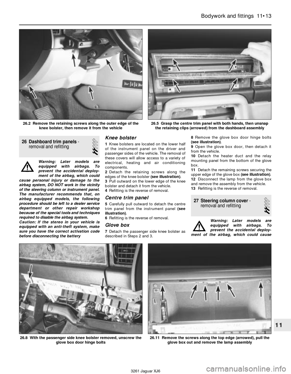
2Detach the retaining screws along the
edges of the knee bolster (see illustration).
3Pull outward on the lower edge of the knee
bolster and detach it from the vehicle.
4Refitting is the reverse of removal.
Centre trim panel
5Carefully pull outward to detach the centre
trim panel from the instrument panel (see
illustration).
6Refitting is the reverse of removal.
Glove box
7Detach the passenger side knee bolster as
described in Steps 2 and 3.8Remove the glove box door hinge bolts
(see illustration).
9Open the glove box door, then detach it
from the vehicle.
10Detach the heater duct and the relay
mounting panel from the bottom of the glove
box.
11Detach the remaining screws securing the
upper edge of the glove box (see illustration).
12Disconnect the lamp from the glove box
and remove the assembly from the vehicle.
13Refitting is the reverse of removal.
27 Steering column cover-
removal and refitting
2
Warning: Later models are
equipped with airbags. To
prevent the accidental deploy-
ment of the airbag, which could cause
Bodywork and fittings 11•13
11
3261 Jaguar XJ6 26.2 Remove the retaining screws along the outer edge of the
knee bolster, then remove it from the vehicle
26.5 Grasp the centre trim panel with both hands, then unsnap
the retaining clips (arrowed) from the dashboard assembly
26.8 With the passenger side knee bolster removed, unscrew the
glove box door hinge bolts26.11 Remove the screws along the top edge (arrowed), pull the
glove box out and remove the lamp assembly
Page 162 of 227

personal injury or damage to the airbag
system, DO NOT work in the vicinity of the
steering column or instrument panel. The
manufacturer recommends that, on airbag
equipped models, the following procedure
should be left to a dealer service
department or other repair workshop
because of the special tools and techniques
required to disable the airbag system.
1Remove the steering wheel (Chapter 10)
2Remove the knob from the rheostat
(dimmer) for the instrument panel lights (see
illustration).
3Remove the lower steering column cover
screws (see illustration), then detach the
lower cover.
4Working through the lower cover opening,
remove the four screws securing the upper
half of the cover, then pull the cover forward
and out to remove it (see illustration).
5Refitting is the reverse of removal.
28 Cowl cover-
removal and refitting
2
1Remove the windscreen wiper arms (see
Chapter 12).2Remove the retaining screws located along
the top of the cowl cover (see illustration).
3Lift the cowl cover up slightly, then detach
the electrical connectors and the spray nozzle
hoses from the backside of the cowl cover.
4Detach the cowl cover from the vehicle.
5Refitting is the reverse of removal.
29 Seats- removal and refitting
2
Front seat
1Position the seat all the way forward or all
the way to the rear to access the front seat
retaining bolts.
2Detach any bolt trim covers and remove the
retaining bolts (see illustration).
3Tilt the seat upward to access the
underneath, then unplug any electrical
connectors and lift the seat from the vehicle.
4Refitting is the reverse of removal.
Rear seat
5Remove retaining screws at the lower edge
of the seat cushion (see illustration). Then lift
up on the front edge and remove the cushion
from the vehicle.
6Detach the retaining bolts at the lower edge
of the seat back.
7Lift up on the lower edge of the seat back to
release the clips securing the top. Then
remove it from the vehicle.
8Refitting is the reverse of removal.
11•14 Bodywork and fittings
27.4 Remove the four screws securing the
upper half of the steering column cover
28.2 Remove the screws (arrowed)
located along the top of the cowl cover29.2 Use a Torx bit to remove the front
seat retaining bolts (arrowed)
3261 Jaguar XJ6 27.2 Pull off the knob from the instrument panel light rheostat
27.3 Remove the lower steering column cover screws
29.5 Detach the screws (arrowed) along
the lower edge of the seat cove
Page 165 of 227
wash system, radio memory and the ABS
main feed and pump circuits.
In-line fuses are located through out the
vehicle depending on the year, make and
model. Consult the wiring diagrams at the end
of this Chapter for further information.
In-line fuses also have a blade terminal
design, which allow fingertip removal and
renewal. If an electrical component fails,
always check the fuse first. A blown fuse is
easily identified through the clear plastic
body. Inspect the element for evidence of
damage (see illustration 3.3).
Be sure to renew blown fuses with the
correct type. Fuses are usually colour-coded
to indicate their rating. Fuses of different
ratings are physically interchangeable, but
only fuses of the proper rating should be
used. Replacing a fuse with one of a different
value than specified is not recommended.
Each electrical circuit needs a specific
amount of protection. The amperage value of
each fuse is moulded into the fuse body.If the renewal fuse immediately fails, don’t
renew it again until the cause of the problem
is isolated and corrected. Don’t substitute
anything else for the fuse. In most cases, this
will be a short circuit in the wiring caused by a
broken or deteriorated wire.
5 Circuit breakers-
general information
Circuit breakers generally protect
components such as electric windows, central
locking and headlights. On some models the
circuit breaker resets itself automatically, so
an electrical overload in the circuit will cause it
to fail momentarily, then come back on. If the
circuit doesn’t come back on, check it
immediately. Once the condition is corrected,
the circuit breaker will resume its normal
function. Some circuit breakers have a button
on top and must be reset manually.To test a circuit breaker, use an ohmmeter
to check continuity between the terminals. A
reading of zero to 1.0 ohms indicates a good
circuit breaker. An open circuit reading on the
meter indicates a bad circuit breaker.
6 Relays- general information
and testing
2
General information
Several electrical accessories in the vehicle,
such as the fuel injection system, electric
windows, central locking, etc, use relays to
transmit the electrical signal to the component.
Relays use a low-current circuit (the control
circuit) to open and close a high-current circuit
(the power circuit). If the relay is defective, that
component will not operate properly. The
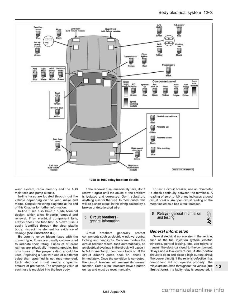
relays are mounted throughout the vehicle (see
illustrations). If a faulty relay is suspected, it
Body electrical system 12•3
12
3261 Jaguar XJ6 1988 to 1989 relay location details
Page 167 of 227

of the airbag, which could cause personal
injury or damage to the airbag system, DO
NOT work in the vicinity of the steering
column or instrument panel. The
manufacturer recommends that, on airbag
equipped models, the following procedure
be performed at a dealer service
department or other properly equipped
repair facility because of the special tools
and techniques required to disable the
airbag system.
The direction indicator and hazard flasher
systems are governed by the central
processing unit. The central processing unit
requires special testers and diagnostic
procedures which are beyond the scope of
this manual.
If the direction indicator/hazard flasher
system fails and the indicator bulbs are in
working condition take the vehicle to a dealer
service department or an automotive
electrical specialist for further diagnosis and
repair.8 Steering column switches-
removal and refitting
1
Warning: Later models are
equipped with airbags. To
prevent accidental deployment
of the airbag, which could cause
personal injury or damage to the airbag
system, DO NOT work in the vicinity of the
steering column or instrument panel. The
manufacturer recommends that, on airbag
equipped models, the following procedure
be performed at a dealer service
department or other properly equipped
repair facility because of the special tools
and techniques required to disable the
airbag system.
Caution: If the stereo in your vehicle is
equipped with an anti-theft system, make
sure you have the correct activation code
before disconnecting the battery.1Disconnect the negative battery cable.
2Remove the steering wheel (Chapter 10).
3Remove the lower steering column cover
(see Chapter 11).
4Remove the switch retaining screw(s) (see
illustration).
Body electrical system 12•5
12
3261 Jaguar XJ6 1993 to 1994 relay location details
8.4 Remove the switch retaining screws,
disconnect the electrical connectors and
pull the switches outward (arrowed)
Page 168 of 227
5Disconnect the electrical connectors from
underneath the steering column and remove
the switch or switches from the vehicle.
6Refitting is the reverse of removal.
9 Ignition switch
and key lock cylinder-
removal and refitting
2
Warning: Later models are
equipped with airbags. To
prevent accidental deployment
of the airbag, which could cause
personal injury or damage to the airbag
system, DO NOT work in the vicinity of the
steering column or instrument panel. The
manufacturer recommends that, on airbag
equipped models, the following procedure
be performed at a dealer service
department or other properly equipped
repair facility because of the special tools
and techniques required to disable the
airbag system.
Caution: If the stereo in your vehicle is
equipped with an anti-theft system, make
sure you have the correct activation code
before disconnecting the battery.1Disconnect the negative battery cable.
2Remove the steering wheel (Chapter 10).
3Remove the steering column trim covers
(see Chapter 11).
4Remove the steering column switch
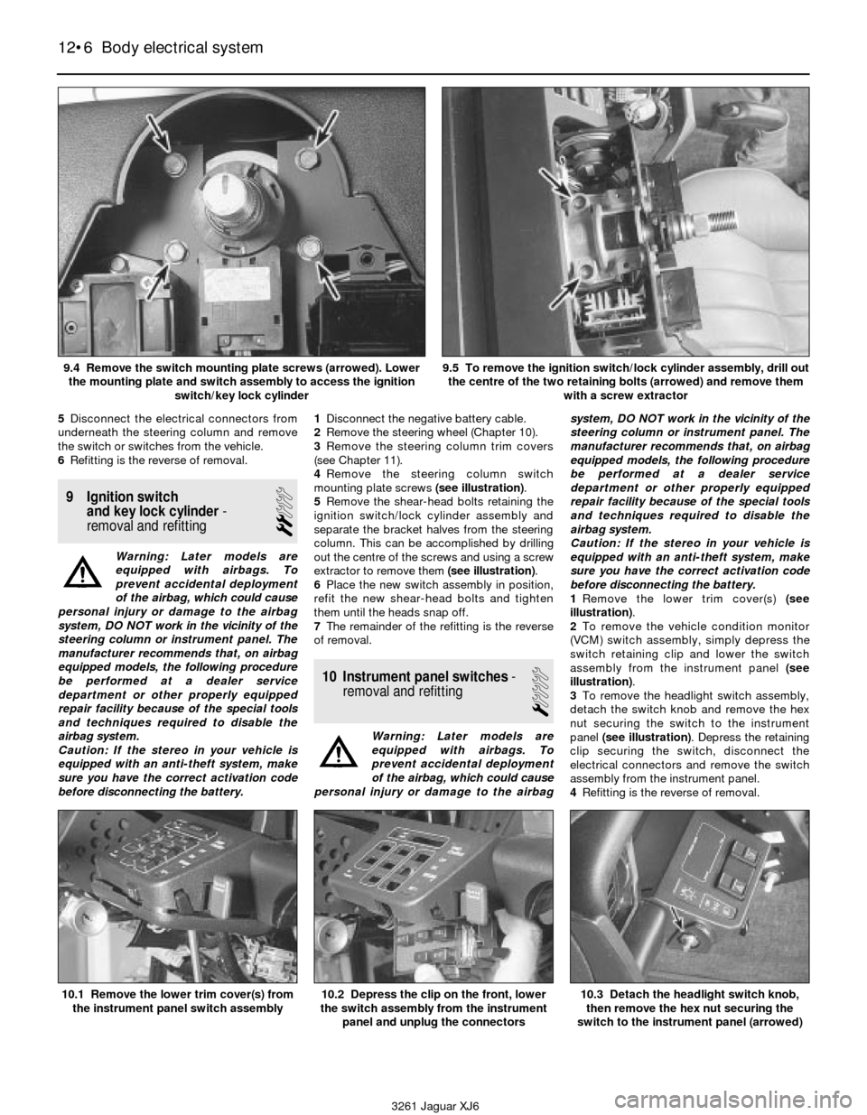
mounting plate screws (see illustration).
5Remove the shear-head bolts retaining the
ignition switch/lock cylinder assembly and
separate the bracket halves from the steering
column. This can be accomplished by drilling
out the centre of the screws and using a screw
extractor to remove them (see illustration).
6Place the new switch assembly in position,
refit the new shear-head bolts and tighten
them until the heads snap off.
7The remainder of the refitting is the reverse
of removal.
10 Instrument panel switches-
removal and refitting
1
Warning: Later models are
equipped with airbags. To
prevent accidental deployment
of the airbag, which could cause
personal injury or damage to the airbagsystem, DO NOT work in the vicinity of the
steering column or instrument panel. The
manufacturer recommends that, on airbag
equipped models, the following procedure
be performed at a dealer service
department or other properly equipped
repair facility because of the special tools
and techniques required to disable the
airbag system.
Caution: If the stereo in your vehicle is
equipped with an anti-theft system, make
sure you have the correct activation code
before disconnecting the battery.
1Remove the lower trim cover(s) (see
illustration).
2To remove the vehicle condition monitor
(VCM) switch assembly, simply depress the
switch retaining clip and lower the switch
assembly from the instrument panel (see
illustration).
3To remove the headlight switch assembly,
detach the switch knob and remove the hex
nut securing the switch to the instrument
panel (see illustration). Depress the retaining
clip securing the switch, disconnect the
electrical connectors and remove the switch
assembly from the instrument panel.
4Refitting is the reverse of removal.
12•6 Body electrical system
10.1 Remove the lower trim cover(s) from
the instrument panel switch assembly10.2 Depress the clip on the front, lower
the switch assembly from the instrument
panel and unplug the connectors10.3 Detach the headlight switch knob,
then remove the hex nut securing the
switch to the instrument panel (arrowed)
3261 Jaguar XJ6 9.4 Remove the switch mounting plate screws (arrowed). Lower
the mounting plate and switch assembly to access the ignition
switch/key lock cylinder
9.5 To remove the ignition switch/lock cylinder assembly, drill out
the centre of the two retaining bolts (arrowed) and remove them
with a screw extractor
Page 169 of 227

11 Fuel, oil and temperature
gauges- check
1
Warning: Later models are
equipped with airbags. To
prevent accidental deployment
of the airbag, which could cause
personal injury or damage to the airbag
system, DO NOT work in the vicinity of the
steering column or instrument panel. The
manufacturer recommends that, on airbag
equipped models, the following procedure
be performed at a dealer service
department or other properly equipped
repair facility because of the special tools
and techniques required to disable the
airbag system.
1All tests below require the ignition switch to
be turned to ON position when testing.
2Check the fuse if the gauge pointer does
not move from the empty, low or cold
positions. If the fuse is OK, locate the
particular sender unit for the circuit you’re
working on (see Chapter 4 for fuel sender unit
location, Chapter 2 for oil sender unit location,
or Chapter 3 for temperature sender unit
location). Connect the sender unit connector
to earth If the pointer goes to the full, high or
hot position renew the sender unit. If the
pointer stays in same position use a jumper
wire to earth the terminal on the back of the
gauge. If the pointer moves with the back of
the gauge earthed the problem lies in the wire
between the gauge and the sender unit. If the
pointer does not moves with the back of the
gauge earthed check for voltage at the other
terminal of the gauge. If voltage is present
renew the gauge.
12 Instrument cluster-
removal and refitting
1
Warning: Later models are
equipped with airbags. To
prevent accidental deployment
of the airbag, which could cause
personal injury or damage to the airbag
system, DO NOT work in the vicinity of the
steering column or instrument panel. The
manufacturer recommends that, on airbag
equipped models, the following procedure
be performed at a dealer service
department or other properly equipped
repair facility because of the special tools
and techniques required to disable the
airbag system.
Caution: If the stereo in your vehicle is
equipped with an anti-theft system, make
sure you have the correct activation code
before disconnecting the battery.
1Disconnect the negative battery cable.
2Remove the instrument cluster housing (see
Chapter 11).
3Remove the instrument cluster mounting
screws (see illustration). Separate the
instrument cluster from the cluster housing.
4Refitting is the reverse of removal.
13 Radio and speakers-
removal and refitting
2
Warning: Later models are
equipped with airbags. To
prevent accidental deployment
of the airbag, which could cause
personal injury or damage to the airbag
system, DO NOT work in the vicinity of the
steering column or instrument panel. The
manufacturer recommends that, on airbagequipped models, the following procedure
be performed at a dealer service
department or other properly equipped
repair facility because of the special tools
and techniques required to disable the
airbag system.
Caution: If the stereo in your vehicle is
equipped with an anti-theft system, make
sure you have the correct activation code
before disconnecting the battery.
1Disconnect the negative battery cable.
Radio
2Remove the radio trim bezel (Chapter 11).
3Remove the retaining screws (see
illustration), pull the radio/control panel
outward to access the backside and
disconnect the electrical connectors and
aerial lead. Detach the retaining clips and
separate the radio from the control panel.
4Refitting is the reverse of removal.
Speakers
5Remove the door trim panel (Chapter 11).
6Remove the nuts from the speaker
mounting studs (see illustration). Disconnect
the electrical connector and remove the
speaker from the vehicle.
7Refitting is the reverse of removal.
Body electrical system 12•7
12
3261 Jaguar XJ6 12.3 Remove the instrument cluster retaining screws (arrowed)
then separate the instrument cluster from the cluster housing
13.3 Remove the retaining screws (arrowed) and pull the
radio/control panel out enough to unplug the connectors
13.6 Remove the nuts from the retaining
studs (arrowed) to remove the speaker