Oxygen sensor JAGUAR XJ6 1997 2.G Workshop Manual
[x] Cancel search | Manufacturer: JAGUAR, Model Year: 1997, Model line: XJ6, Model: JAGUAR XJ6 1997 2.GPages: 227, PDF Size: 7.2 MB
Page 41 of 227
8Tighten the screws to the torque listed in
this Chapter’s Specifications in three or four
equal steps.
9Refit the remaining components, start the
engine and check for oil leaks.
5 Intake manifold-
removal and refitting
2
Removal
1Disconnect the negative cable from the
battery.
Caution: If the stereo in your vehicle is
equipped with an anti-theft system, make
sure you have the correct activation code
before disconnecting the battery.
2Refer to Chapter 4 to remove the
accelerator and cruise-control linkage, safely
relieve the fuel system pressure, and
disconnect the fuel supply lines.
3Label or mark and detach the PCV and
vacuum hoses connected to the intake
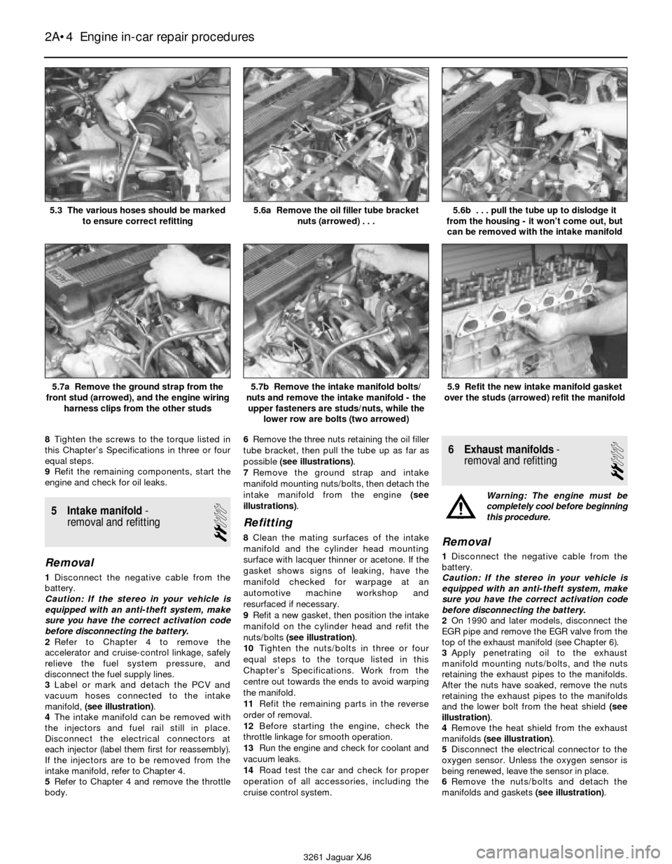
manifold, (see illustration).
4The intake manifold can be removed with
the injectors and fuel rail still in place.
Disconnect the electrical connectors at
each injector (label them first for reassembly).
If the injectors are to be removed from the
intake manifold, refer to Chapter 4.
5Refer to Chapter 4 and remove the throttle
body.6Remove the three nuts retaining the oil filler
tube bracket, then pull the tube up as far as
possible (see illustrations).
7Remove the ground strap and intake
manifold mounting nuts/bolts, then detach the
intake manifold from the engine (see
illustrations).
Refitting
8Clean the mating surfaces of the intake
manifold and the cylinder head mounting
surface with lacquer thinner or acetone. If the
gasket shows signs of leaking, have the
manifold checked for warpage at an
automotive machine workshop and
resurfaced if necessary.
9Refit a new gasket, then position the intake
manifold on the cylinder head and refit the
nuts/bolts (see illustration).
10Tighten the nuts/bolts in three or four
equal steps to the torque listed in this
Chapter’s Specifications. Work from the
centre out towards the ends to avoid warping
the manifold.
11Refit the remaining parts in the reverse
order of removal.
12Before starting the engine, check the
throttle linkage for smooth operation.
13Run the engine and check for coolant and
vacuum leaks.
14Road test the car and check for proper
operation of all accessories, including the
cruise control system.
6 Exhaust manifolds-
removal and refitting
2
Warning: The engine must be
completely cool before beginning
this procedure.
Removal
1Disconnect the negative cable from the
battery.
Caution: If the stereo in your vehicle is
equipped with an anti-theft system, make
sure you have the correct activation code
before disconnecting the battery.
2On 1990 and later models, disconnect the
EGR pipe and remove the EGR valve from the
top of the exhaust manifold (see Chapter 6).
3Apply penetrating oil to the exhaust
manifold mounting nuts/bolts, and the nuts
retaining the exhaust pipes to the manifolds.
After the nuts have soaked, remove the nuts
retaining the exhaust pipes to the manifolds
and the lower bolt from the heat shield (see
illustration).
4Remove the heat shield from the exhaust
manifolds(see illustration).
5Disconnect the electrical connector to the
oxygen sensor. Unless the oxygen sensor is
being renewed, leave the sensor in place.
6Remove the nuts/bolts and detach the
manifolds and gaskets (see illustration).
2A•4 Engine in-car repair procedures
5.3 The various hoses should be marked
to ensure correct refitting5.6a Remove the oil filler tube bracket
nuts (arrowed) . . .5.6b . . . pull the tube up to dislodge it
from the housing - it won’t come out, but
can be removed with the intake manifold
5.7a Remove the ground strap from the
front stud (arrowed), and the engine wiring
harness clips from the other studs5.7b Remove the intake manifold bolts/
nuts and remove the intake manifold - the
upper fasteners are studs/nuts, while the
lower row are bolts (two arrowed)5.9 Refit the new intake manifold gasket
over the studs (arrowed) refit the manifold
3261 Jaguar XJ6
Page 90 of 227
special electrical device that provides circuit
protection by switching off the ignition and
fuel pump upon impact in the event of vehicle
collision. Later Jaguar models are equipped
with an additional specialised inertia switch.
This later device switches OFF all ignition fed
circuits, locks the fuel filler cap, locks the boot
(only if doors are locked) and unlocks the
doors if they are locked during the accident.
All these functions are directed by the inertia
switch. The inertia switch is located behind
the left kick panel. Refer to Chapter 12 for
more information.
Exhaust system
The exhaust system includes an exhaust
manifold equipped with an exhaust oxygen
sensor, a catalytic converter, an exhaust pipe,
and a silencer.
The catalytic converter is an emission
control device added to the exhaust system to
reduce pollutants. A single-bed converter is
used in combination with a three-way
(reduction) catalyst. See Chapter 6 for more
information regarding the catalytic converter.
2 Fuel pressure relief
1
Warning: Petrol is extremely
flammable, so take extra
precautions when you work on
any part of the fuel system.
Don’t smoke or allow open flames or bare
light bulbs near the work area, and don’t
work in a garage where a natural gas-type
appliance (such as a water heater or a
clothes dryer) with a pilot light is present.
Since petrol is carcinogenic, wear latex
gloves when there’s a possibility of being
exposed to fuel, and, if you spill any fuel on
your skin, rinse it off immediately with soap
and water. Mop up any spills immediately
and do not store fuel-soaked rags wherethey could ignite. The fuel system is under
constant pressure, so, if any fuel lines are
to be disconnected, the fuel pressure in
the system must be relieved first. When
you perform any kind of work on the fuel
system, wear safety glasses and have a
Class B type fire extinguisher on hand.
1Before servicing any fuel system
component, you must relieve the fuel pressure
to minimise the risk of fire or personal injury.
2Remove the fuel filler cap - this will relieve
any pressure built up in the tank.
3Remove the fuel pump relay from the main
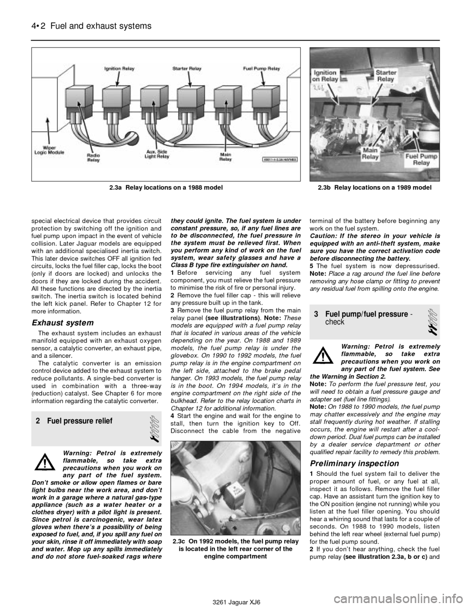
relay panel (see illustrations). Note:These
models are equipped with a fuel pump relay
that is located in various areas of the vehicle
depending on the year. On 1988 and 1989
models, the fuel pump relay is under the
glovebox. On 1990 to 1992 models, the fuel
pump relay is in the engine compartment on
the left side, attached to the brake pedal
hanger. On 1993 models, the fuel pump relay
is in the boot. On 1994 models, it’s in the
engine compartment on the right side of the
bulkhead. Refer to the relay location charts in
Chapter 12 for additional information.
4Start the engine and wait for the engine to
stall, then turn the ignition key to Off.
Disconnect the cable from the negativeterminal of the battery before beginning any
work on the fuel system.
Caution: If the stereo in your vehicle is
equipped with an anti-theft system, make
sure you have the correct activation code
before disconnecting the battery.
5The fuel system is now depressurised.
Note:Place a rag around the fuel line before
removing any hose clamp or fitting to prevent
any residual fuel from spilling onto the engine.
3 Fuel pump/fuel pressure-
check
2
Warning: Petrol is extremely
flammable, so take extra
precautions when you work on
any part of the fuel system. See
the Warning in Section 2.
Note: To perform the fuel pressure test, you
will need to obtain a fuel pressure gauge and
adapter set (fuel line fittings).
Note: On 1988 to 1990 models, the fuel pump
may chatter excessively and the engine may
stall frequently during hot weather. If stalling
occurs, the engine will restart after a cool-
down period. Dual fuel pumps can be installed
by a dealer service department or other
qualified repair facility to remedy this problem.
Preliminary inspection
1Should the fuel system fail to deliver the
proper amount of fuel, or any fuel at all,
inspect it as follows. Remove the fuel filler
cap. Have an assistant turn the ignition key to
the ON position (engine not running) while you
listen at the fuel filler opening. You should
hear a whirring sound that lasts for a couple of
seconds. On 1988 to 1990 models, listen
behind the left rear wheel (external fuel pump)
for the fuel pump sound.
2If you don’t hear anything, check the fuel
pump relay (see illustration 2.3a, b or c)and
4•2 Fuel and exhaust systems
2.3c On 1992 models, the fuel pump relay
is located in the left rear corner of the
engine compartment
3261 Jaguar XJ6 2.3a Relay locations on a 1988 model
2.3b Relay locations on a 1989 model
Page 97 of 227
13Allow the bellcrank to return to the idle
position and test the adjustment once again
until the correct adjustment has been attained.
11 Electronic Fuel Injection
(EFI) system-
general information
1These models are equipped with an
Electronic Fuel Injection (EFI) system. This fuel
injection system is designed by Bosch butlicensed by Lucas and is called the Lucas LH
Engine Management system. The EFI system
is composed of three basic sub systems: fuel
system, air induction system and electronic
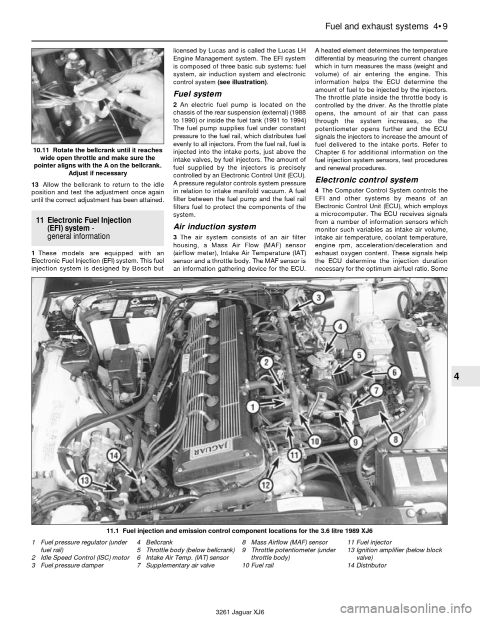
control system (see illustration).
Fuel system
2An electric fuel pump is located on the
chassis of the rear suspension (external) (1988
to 1990) or inside the fuel tank (1991 to 1994)
The fuel pump supplies fuel under constant
pressure to the fuel rail, which distributes fuel
evenly to all injectors. From the fuel rail, fuel is
injected into the intake ports, just above the
intake valves, by fuel injectors. The amount of
fuel supplied by the injectors is precisely
controlled by an Electronic Control Unit (ECU).
A pressure regulator controls system pressure
in relation to intake manifold vacuum. A fuel
filter between the fuel pump and the fuel rail
filters fuel to protect the components of the
system.
Air induction system
3The air system consists of an air filter
housing, a Mass Air Flow (MAF) sensor
(airflow meter), Intake Air Temperature (IAT)
sensor and a throttle body. The MAF sensor is
an information gathering device for the ECU.A heated element determines the temperature
differential by measuring the current changes
which in turn measures the mass (weight and
volume) of air entering the engine. This
information helps the ECU determine the
amount of fuel to be injected by the injectors.
The throttle plate inside the throttle body is
controlled by the driver. As the throttle plate
opens, the amount of air that can pass
through the system increases, so the
potentiometer opens further and the ECU
signals the injectors to increase the amount of
fuel delivered to the intake ports. Refer to
Chapter 6 for additional information on the
fuel injection system sensors, test procedures
and renewal procedures.
Electronic control system
4The Computer Control System controls the
EFI and other systems by means of an
Electronic Control Unit (ECU), which employs
a microcomputer. The ECU receives signals
from a number of information sensors which
monitor such variables as intake air volume,
intake air temperature, coolant temperature,
engine rpm, acceleration/deceleration and
exhaust oxygen content. These signals help
the ECU determine the injection duration
necessary for the optimum air/fuel ratio. Some
Fuel and exhaust systems 4•9
4
10.11 Rotate the bellcrank until it reaches
wide open throttle and make sure the
pointer aligns with the A on the bellcrank.
Adjust if necessary
11.1 Fuel injection and emission control component locations for the 3.6 litre 1989 XJ6
3261 Jaguar XJ6 1 Fuel pressure regulator (under
fuel rail)
2 Idle Speed Control (ISC) motor
3 Fuel pressure damper4 Bellcrank
5 Throttle body (below bellcrank)
6 Intake Air Temp. (IAT) sensor
7 Supplementary air valve8 Mass Airflow (MAF) sensor
9 Throttle potentiometer (under
throttle body)
10 Fuel rail11 Fuel injector
13 Ignition amplifier (below block
valve)
14 Distributor
Page 98 of 227

of these sensors and their corresponding
ECU-controlled relays are not contained
within EFI components, but are located
throughout the engine compartment. For
further information regarding the ECU and its
relationship to the engine electrical and
ignition system, see Chapter 6.
12 Electronic Fuel Injection
(EFI) system- check
2
1Check the earth wire connections for
tightness. Check all wiring and electrical
connectors that are related to the system.
Loose electrical connectors and poor grounds
can cause many problems that resemble
more serious malfunctions.
2Check to see that the battery is fully
charged, as the control unit and sensors
depend on an accurate supply voltage in
order to properly meter the fuel.
3Check the air filter element - a dirty or
partially blocked filter will severely impede
performance and economy (see Chapter 1).
4If a blown fuse is found, renew it and see if
it blows again. If it does, search for a shorted
wire in the harness related to the system.
5Check the air intake duct from the MAF
sensor to the intake manifold for leaks, which
will result in an excessively lean mixture. Also
check the condition of the vacuum hoses
connected to the intake manifold.
6Remove the air intake duct from the throttle
body and check for carbon and residue build-
up. If it’s dirty, clean with aerosol carburettor
cleaner (make sure the can says it’s safe for
use with oxygen sensors and catalytic
converters) and a toothbrush.
7With the engine running, place a
stethoscope against each injector, one at a
time, and listen for a clicking sound, indicating
operation (see illustration).8If there is a problem with an injector,
purchase a special injector test light (noid
light) and refit it into the injector electrical
connector (see illustration). Start the engine
and make sure that each injector connector
flashes the noid light. This will test for the
proper voltage signal to the injector.Caution:
If the engine will not start and the noid
light indicates that each injector is
receiving the proper signal, there is a good
possibility that the injector(s) is stuck open
and allowing fuel into the combustion
chamber in excessive amounts. If the spark
plugs are fouled, detach the primary (low
voltage) wires from the ignition coil, disable
the fuel pump by removing the fuel pump
relay (see Section 2), remove the spark plugs
and crank the engine over. If fuel sprays from
the spark plug holes, the engine is flooded
and the fuel must be removed from the
combustion chambers.
9With the engine OFF and the fuel injector
electrical connectors disconnected, measure
the resistance of each injector (see
illustration). Each injector should measure
about 2.0 to 3.0 ohms. If not, the injector is
probably faulty.10The remainder of the system checks
should be left to a Jaguar service department
or other qualified repair workshop, as there is
a chance that the control unit may be
damaged if not performed properly.
13 Electronic Fuel Injection
(EFI) system- component
check and renewal
3
Warning: Petrol is extremely
flammable, so take extra
precautions when you work on
any part of the fuel system. See
the Warning in Section 2.
Caution: If the stereo in your vehicle is
equipped with an anti-theft system, make
sure you have the correct activation code
before disconnecting the battery.
Throttle body
Check
1Verify that the throttle linkage operates
smoothly.
2Start the engine, detach each vacuum hose
and, using your finger, check the vacuum at
each port on the throttle body with the engine
at idle and above idle. The vacuum available
from the throttle body is ported. Raise the
engine rpm and watch as vacuum increases.
It may be necessary to use a vacuum gauge.
Refer to Chapter 2B for additional information
concerning vacuum checks.
Renewal
Warning: Wait until the engine is
completely cool before
beginning this procedure.
3Detach the cable from the negative terminal
of the battery (see the Cautionat the
beginning of this Section).
4Drain the radiator (see Chapter 1).
4•10 Fuel and exhaust systems
12.9 Using an ohmmeter, measure the
resistance across both terminals
of the injector
3261 Jaguar XJ6 12.7 Use a stethoscope or a screwdriver to determine if the
injectors are working properly - they should make a steady
clicking sound that rises and falls with engine speed changes
12.8 Refit the “noid” light into the fuel injector electrical
connector and check to see that it blinks with the engine running
Page 112 of 227
components identified. When servicing the
engine or emissions systems, the VECI label
in your particular vehicle should always be
checked for up-to-date information.
2 Electronic control system
and ECU
General description
Note: These models are susceptible to ECU
damage if water is allowed to build up in the
front cowl drain and overspill into the dash
area near the computer. Inspect and clear the
front cowl drain as a regular maintenance item
to keep the water draining properly. Remove
the duckbill-type rubber hose and inspect it
for clogging, collapsing or deterioration.
1The Lucas LH Engine Management system
controls the fuel injection system by means of
a microcomputer known as the Electronic
Control unit (ECU).
2The ECU receives signals from various
sensors which monitor changing engine
operating conditions such as intake air mass,
intake air temperature, coolant temperature,
engine rpm, acceleration/deceleration,
exhaust oxygen content, etc. These signals
are utilised by the ECU to determine the
correct injection duration.
3The system is analogous to the central
nervous system in the human body: The
sensors (nerve endings) constantly relay
signals to the ECU (brain), which processes
the data and, if necessary, sends out a
command to change the operating
parameters of the engine (body).
4Here’s a specific example of how one
portion of this system operates: An oxygen
sensor, located in the exhaust manifold,
constantly monitors the oxygen content of the
exhaust gas. If the percentage of oxygen in
the exhaust gas is incorrect, an electrical
signal is sent to the ECU. The ECU takes this
information, processes it and then sends a
command to the fuel injection system telling it
to change the air/fuel mixture. This happens in
a fraction of a second and it goes on
continuously when the engine is running. The
end result is an air/fuel mixture ratio which is
constantly maintained at a predetermined
ratio, regardless of driving conditions.
5In the event of a sensor malfunction, a
backup circuit will take over to provide
driveability until the problem is identified and
fixed.
Precautions
6Follow these steps:
a) Always disconnect the power by either
turning off the ignition switch or
disconnecting the battery terminals before
removing electrical connectors.
Warning: Later models are
equipped with airbags. To
prevent accidental deployment ofthe airbag, which could cause personal
injury, DO NOT work in the vicinity of the
steering column or instrument panel. The
manufacturer recommends that, on airbag
equipped models, the following procedure
should be left to a dealer service
department or other repair workshop
because of the special tools and techniques
required to disable the airbag system.
Caution: If the stereo in your vehicle is
equipped with an anti-theft system, make
sure you have the correct activation code
before disconnecting the battery.
b) When refitting a battery, be particularly
careful to avoid reversing the positive and
negative battery cables. Also, make sure
the ignition key is in the Off position when
connecting or disconnecting the battery.
c) Do not subject EFI components,
emissions-related components or the
ECU to severe impact during removal or
refitting.
d) Do not be careless during fault diagnosis.
Even slight terminal contact can invalidate
a testing procedure and damage one of
the numerous transistor circuits.
e) Never attempt to work on the ECU or
open the ECU cover. The ECU is
protected by a government-mandated
extended warranty that will be nullified if
you tamper with or damage the ECU.
f) If you are inspecting electronic control
system components during rainy weather,
make sure that water does not enter any
part. When washing the engine
compartment, do not spray these parts or
their electrical connectors with water.
g) These models are susceptible to ECU
damage if water is allowed to build up in
the front cowl drain and overspill into the
dash area. Inspect and clear the front
cowl drain system as a regular
maintenance item to keep the water
draining properly. Remove the duckbill
type rubber hose and inspect it for
clogging, collapsing or deterioration.
ECU removal and refitting
7Disconnect the negative cable from the
battery (see Chapter 5).
Warning: Later models are
equipped with airbags. To
prevent the accidental deploy-
ment of the airbag, which could
cause personal injury, DO NOT work in the
vicinity of the steering column or
instrument panel. The manufacturer
recommends that, on airbag equipped
models, the following procedure should be
left to a dealer service department or other
repair workshop because of the special
tools and techniques required to disable
the airbag system.
Caution: If the stereo in your vehicle is
equipped with an anti-theft system, make
sure you have the correct activation code
before disconnecting the battery.8Remove the lower instrument panel on the
passenger side under the glove compartment
(see Chapter 11).
9Remove the glove compartment from the
passenger compartment (see Chapter 11).
10Remove the screws from the ECU bracket
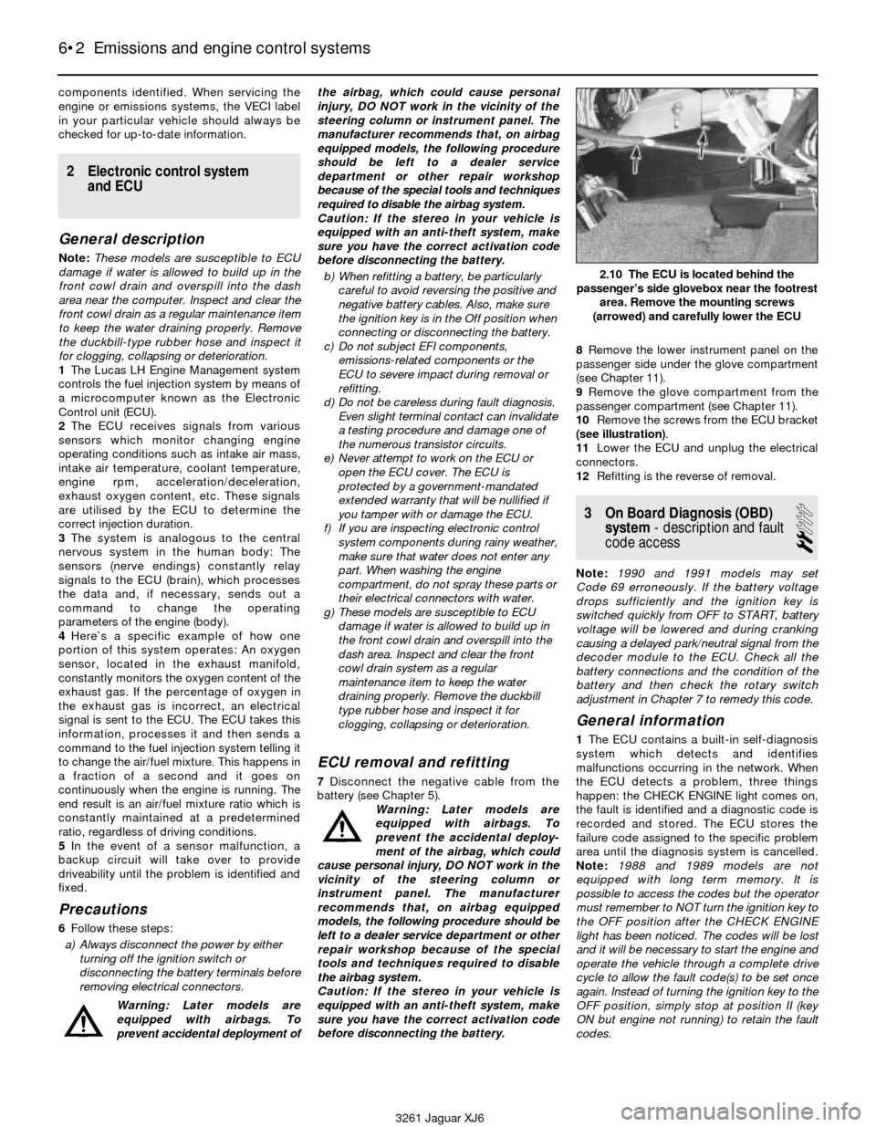
(see illustration).
11Lower the ECU and unplug the electrical
connectors.
12Refitting is the reverse of removal.
3 On Board Diagnosis (OBD)
system- description and fault
code access
2
Note: 1990 and 1991 models may set
Code 69 erroneously. If the battery voltage
drops sufficiently and the ignition key is
switched quickly from OFF to START, battery
voltage will be lowered and during cranking
causing a delayed park/neutral signal from the
decoder module to the ECU. Check all the
battery connections and the condition of the
battery and then check the rotary switch
adjustment in Chapter 7 to remedy this code.
General information
1The ECU contains a built-in self-diagnosis
system which detects and identifies
malfunctions occurring in the network. When
the ECU detects a problem, three things
happen: the CHECK ENGINE light comes on,
the fault is identified and a diagnostic code is
recorded and stored. The ECU stores the
failure code assigned to the specific problem
area until the diagnosis system is cancelled.
Note: 1988 and 1989 models are not
equipped with long term memory. It is
possible to access the codes but the operator
must remember to NOT turn the ignition key to
the OFF position after the CHECK ENGINE
light has been noticed. The codes will be lost
and it will be necessary to start the engine and
operate the vehicle through a complete drive
cycle to allow the fault code(s) to be set once
again. Instead of turning the ignition key to the
OFF position, simply stop at position II (key
ON but engine not running) to retain the fault
codes.
6•2 Emissions and engine control systems
3261 Jaguar XJ6
2.10 The ECU is located behind the
passenger’s side glovebox near the footrest
area. Remove the mounting screws
(arrowed) and carefully lower the ECU
Page 113 of 227
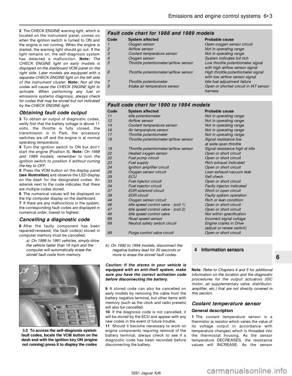
2The CHECK ENGINE warning light, which is
located on the instrument panel, comes on
when the ignition switch is turned to ON and
the engine is not running. When the engine is
started, the warning light should go out. If the
light remains on, the self-diagnosis system
has detected a malfunction. Note: The
CHECK ENGINE light on early models is
displayed on the dashboard VCM panel on the
right side. Later models are equipped with a
separate CHECK ENGINE light on the left side
of the instrument cluster.Note:Not all the
codes will cause the CHECK ENGINE light to
activate. When performing any fuel or
emissions systems diagnosis, always check
for codes that may be stored but not indicated
by the CHECK ENGINE light.
Obtaining fault code output
3To obtain an output of diagnostic codes,
verify first that the battery voltage is above 11
volts, the throttle is fully closed, the
transmission is in Park, the accessory
switches are off and the engine is at normal
operating temperature.
4Turn the ignition switch to ON but don’t
start the engine (Position II). Note:On 1988
and 1989 models, remember to turn the
ignition switch to position II without turning
the key to OFF.
5Press the VCM button on the display panel
(see illustration)and observe the LED display
on the dash for the designated codes. An
asterisk next to the code indicates that there
are multiple codes stored.
6The numerical values will be displayed on
the trip computer display on the dashboard.
7If there are any malfunctions in the system,
the corresponding fault codes are displayed in
numerical order, lowest to highest.
Cancelling a diagnostic code
8After the faulty component has been
repaired/renewed, the fault code(s) stored in
computer memory must be cancelled.
a) On 1988 to 1991 vehicles, simply drive
the vehicle faster than 19 mph and the
computer will automatically erase the
stored fault code from memory.b) On 1992 to 1994 models, disconnect the
negative battery lead for 30 seconds or
more to erase the stored fault codes.
Caution: If the stereo in your vehicle is
equipped with an anti-theft system, make
sure you have the correct activation code
before disconnecting the battery.
9A stored code can also be cancelled on
early models by removing the cable from the
battery negative terminal, but other items with
memory (such as the clock and radio presets)
will also be cancelled.
10If the diagnosis code is not cancelled, it
will be stored by the ECU and appear with any
new codes in the event of future trouble.
11Should it become necessary to work on
engine components requiring removal of the
battery terminal, always check to see if a
diagnostic code has been recorded before
disconnecting the battery.
4 Information sensors
Note: Refer to Chapters 4 and 5 for additional
information on the location and the diagnostic
procedures for the output actuators (ISC
motor, air supplementary valve, distributor,
amplifier, etc.) that are not directly covered in
this section.
Coolant temperature sensor
General description
1The coolant temperature sensor is a
thermistor (a resistor which varies the value of
its voltage output in accordance with
temperature changes) which is threaded into
the thermostat housing. As the sensor
temperature DECREASES, the resistance
values will INCREASE. As the sensor
Emissions and engine control systems 6•3
6
3.5 To access the self-diagnosis system
fault codes, locate the VCM button on the
dash and with the ignition key ON (engine
not running) press it to display the codes
3261 Jaguar XJ6
Fault code chart for 1988 and 1989 models
Code System affected Probable cause
1 Oxygen sensor Open oxygen sensor circuit
2 Airflow sensor Not in operating range
3 Coolant temperature sensor Not in operating range
4 Oxygen sensor System indicates full rich
5 Throttle potentiometer/airflow sensor Low throttle potentiometer signal
with high airflow sensor signal
6 Throttle potentiometer/airflow sensor High throttle potentiometer signal
with low airflow sensor signal
7 Throttle potentiometer Idle fuel adjustment failure
8 Intake air temperature sensor Open or shorted circuit in IAT sensor
harness
Fault code chart for 1990 to 1994 models
Code System affected Probable cause
11 Idle potentiometer Not in operating range
12 Airflow sensor Not in operating range
14 Coolant temperature sensor Not in operating range
16 Air temperature sensor Not in operating range
17 Throttle potentiometer Not in operating range
18 Throttle potentiometer/airflow sensor Signal resistance low
at wide open throttle
19 Throttle potentiometer/airflow sensor Signal resistance high at idle
22 Heated oxygen sensor Open or short circuit
22 Fuel pump circuit Open or short circuit
23 Fuel supply Rich exhaust Indicated
24 Ignition amplifier circuit Open or short circuit
26 Oxygen sensor circuit Lean exhaust/vacuum leak
29 ECU Self check
33 Fuel injector circuit Open or short circuit
34 Fuel injector circuit Faulty injector indicated
37 EGR solenoid circuit Short or open circuit
39 EGR circuit Faulty system operation
44 Oxygen sensor circuit Rich or lean condition
46 Idle speed control valve - (coil 1) Open or short circuit
47 Idle speed control valve - (coil 2) Open or short circuit
48 Idle speed control valve Not within specification
68 Road speed sensor Incorrect signal voltage
69 Neutral safety switch circuit Engine cranks in Drive
(adjust or renew switch)
89 Purge control valve circuit Open or short circuit
Page 114 of 227
temperature INCREASES, the resistance
values will DECREASE. A failure in this sensor
circuit should set a Code 3 (1988 and 1989)
or 13 (1990 to 1994). This code indicates a
failure in the coolant temperature sensor
circuit, so in most cases the appropriate
solution to the problem will be either repair of
a connector or wire, or renewal of the sensor.
Check
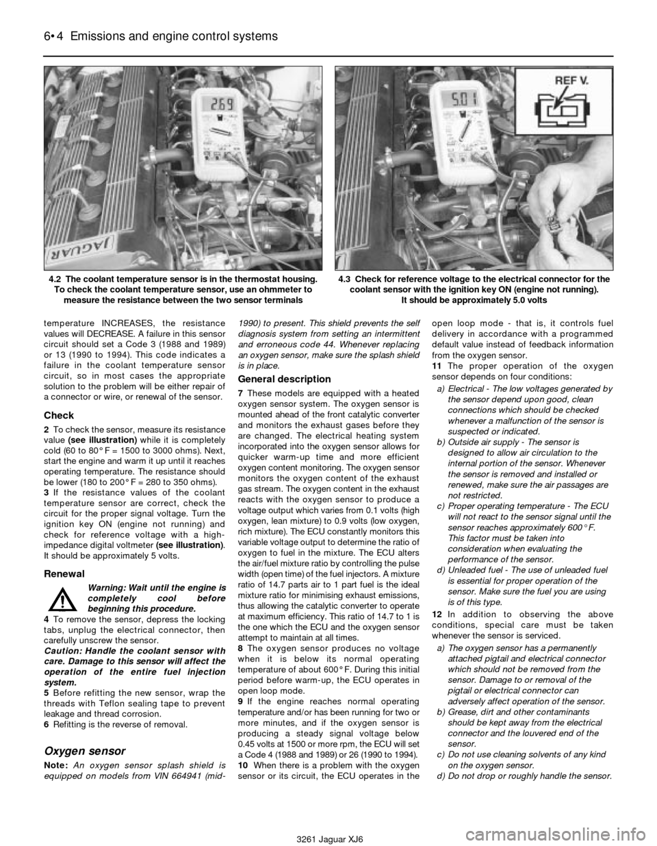
2To check the sensor, measure its resistance
value (see illustration)while it is completely
cold (60 to 80° F = 1500 to 3000 ohms). Next,
start the engine and warm it up until it reaches
operating temperature. The resistance should
be lower (180 to 200° F = 280 to 350 ohms).
3If the resistance values of the coolant
temperature sensor are correct, check the
circuit for the proper signal voltage. Turn the
ignition key ON (engine not running) and
check for reference voltage with a high-
impedance digital voltmeter (see illustration).
It should be approximately 5 volts.
Renewal
Warning: Wait until the engine is
completely cool before
beginning this procedure.
4To remove the sensor, depress the locking
tabs, unplug the electrical connector, then
carefully unscrew the sensor.
Caution: Handle the coolant sensor with
care. Damage to this sensor will affect the
operation of the entire fuel injection
system.
5Before refitting the new sensor, wrap the
threads with Teflon sealing tape to prevent
leakage and thread corrosion.
6Refitting is the reverse of removal.
Oxygen sensor
Note:An oxygen sensor splash shield is
equipped on models from VIN 664941 (mid-1990) to present. This shield prevents the self
diagnosis system from setting an intermittent
and erroneous code 44. Whenever replacing
an oxygen sensor, make sure the splash shield
is in place.
General description
7These models are equipped with a heated
oxygen sensor system. The oxygen sensor is
mounted ahead of the front catalytic converter
and monitors the exhaust gases before they
are changed. The electrical heating system
incorporated into the oxygen sensor allows for
quicker warm-up time and more efficient
oxygen content monitoring. The oxygen sensor
monitors the oxygen content of the exhaust
gas stream. The oxygen content in the exhaust
reacts with the oxygen sensor to produce a
voltage output which varies from 0.1 volts (high
oxygen, lean mixture) to 0.9 volts (low oxygen,
rich mixture). The ECU constantly monitors this
variable voltage output to determine the ratio of
oxygen to fuel in the mixture. The ECU alters
the air/fuel mixture ratio by controlling the pulse
width (open time) of the fuel injectors. A mixture
ratio of 14.7 parts air to 1 part fuel is the ideal
mixture ratio for minimising exhaust emissions,
thus allowing the catalytic converter to operate
at maximum efficiency. This ratio of 14.7 to 1 is
the one which the ECU and the oxygen sensor
attempt to maintain at all times.
8The oxygen sensor produces no voltage
when it is below its normal operating
temperature of about 600° F. During this initial
period before warm-up, the ECU operates in
open loop mode.
9If the engine reaches normal operating
temperature and/or has been running for two or
more minutes, and if the oxygen sensor is
producing a steady signal voltage below
0.45 volts at 1500 or more rpm, the ECU will set
a Code 4 (1988 and 1989) or 26 (1990 to 1994).
10When there is a problem with the oxygen
sensor or its circuit, the ECU operates in theopen loop mode - that is, it controls fuel
delivery in accordance with a programmed
default value instead of feedback information
from the oxygen sensor.
11The proper operation of the oxygen
sensor depends on four conditions:
a) Electrical - The low voltages generated by
the sensor depend upon good, clean
connections which should be checked
whenever a malfunction of the sensor is
suspected or indicated.
b) Outside air supply - The sensor is
designed to allow air circulation to the
internal portion of the sensor. Whenever
the sensor is removed and installed or
renewed, make sure the air passages are
not restricted.
c) Proper operating temperature - The ECU
will not react to the sensor signal until the
sensor reaches approximately 600° F.
This factor must be taken into
consideration when evaluating the
performance of the sensor.
d) Unleaded fuel - The use of unleaded fuel
is essential for proper operation of the
sensor. Make sure the fuel you are using
is of this type.
12In addition to observing the above
conditions, special care must be taken
whenever the sensor is serviced.
a) The oxygen sensor has a permanently
attached pigtail and electrical connector
which should not be removed from the
sensor. Damage to or removal of the
pigtail or electrical connector can
adversely affect operation of the sensor.
b) Grease, dirt and other contaminants
should be kept away from the electrical
connector and the louvered end of the
sensor.
c) Do not use cleaning solvents of any kind
on the oxygen sensor.
d) Do not drop or roughly handle the sensor.
6•4 Emissions and engine control systems
3261 Jaguar XJ6 4.2 The coolant temperature sensor is in the thermostat housing.
To check the coolant temperature sensor, use an ohmmeter to
measure the resistance between the two sensor terminals
4.3 Check for reference voltage to the electrical connector for the
coolant sensor with the ignition key ON (engine not running).
It should be approximately 5.0 volts
Page 115 of 227
e) The silicone boot must be installed in the
correct position to prevent the boot from
being melted and to allow the sensor to
operate properly.
Check
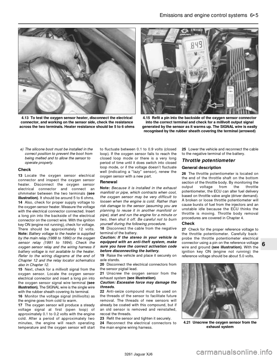
13Locate the oxygen sensor electrical
connector and inspect the oxygen sensor
heater. Disconnect the oxygen sensor
electrical connector and connect an
ohmmeter between the two terminals (see
illustration). It should be around 5 to 6 ohms.
14Also, check for proper supply voltage to
the oxygen sensor heater. Measure the voltage
with the electrical connector connected. Insert
a long pin into the backside of the electrical
connector on the correct wire. With the ignition
key ON (engine not running), check for voltage.
There should be approximately 12 volts.
Note:Battery voltage to the heater is supplied
by the main relay (1988 to 1990) or the oxygen
sensor relay (1991 to 1994). Check the
oxygen sensor relay and the wiring harness if
battery voltage is not available to the heater.
Refer to the wiring diagrams at the end of
Chapter 12 and the relay locator schematics
also in Chapter 12.
15Next, check for a millivolt signal from the
oxygen sensor. Locate the oxygen sensor
electrical connector and insert a long pin into
the oxygen sensor signal wire terminal (see
illustration). The SIGNAL wire is the single wire
with the rubber sheath covering its terminal.
16Monitor the voltage signal (millivolts) as
the engine goes from cold to warm.
17The oxygen sensor will produce a steady
voltage signal at first (open loop) of
approximately 0.1 to 0.2 volts with the engine
cold. After a period of approximately two
minutes, the engine will reach operating
temperature and the oxygen sensor will startto fluctuate between 0.1 to 0.9 volts (closed
loop). If the oxygen sensor fails to reach the
closed loop mode or there is a very long
period of time until it does switch into closed
loop mode, or if the voltage doesn’t fluctuate
well (indicating a “lazy” sensor), renew the
oxygen sensor with a new part.
Renewal
Note:Because it is installed in the exhaust
manifold or pipe, which contracts when cool,
the oxygen sensor may be very difficult to
loosen when the engine is cold. Rather than
risk damage to the sensor (assuming you are
planning to reuse it in another manifold or
pipe), start and run the engine for a minute or
two, then shut it off. Be careful not to burn
yourself during the following procedure.
18Disconnect the cable from the negative
terminal of the battery.
Caution: If the stereo in your vehicle is
equipped with an anti-theft system, make
sure you have the correct activation code
before disconnecting the battery.
19Raise the vehicle and place it securely on
axle stands.
20Disconnect the electrical connectors from
the sensor pigtail lead.
21Unscrew the oxygen sensor from the
exhaust system (see illustration).
Caution: Excessive force may damage the
threads.
22Anti-seize compound must be used on
the threads of the sensor to facilitate future
removal. The threads of new sensors will
already be coated with this compound, but if
an old sensor is removed and reinstalled,
recoat the threads.
23Refit the sensor and tighten it securely.
24Reconnect the electrical connectors to
the main engine wiring harness.25Lower the vehicle and reconnect the cable
to the negative terminal of the battery.
Throttle potentiometer
General description
26The throttle potentiometer is located on
the end of the throttle shaft on the bottom
section of the throttle body. By monitoring the
output voltage from the throttle
potentiometer, the ECU can alter fuel delivery
based on throttle valve angle (driver demand).
A broken or loose throttle potentiometer will
cause bursts of fuel from the injectors and an
unstable idle because the ECU thinks the
throttle is moving. Throttle body removal
procedures are covered in Chapter 4.
Check
27Check for the proper reference voltage to
the throttle potentiometer. Carefully back-
probe the throttle potentiometer electrical
connector using a pin on the reference voltage
wire and ground (see illustration). With the
ignition key ON (engine not running) the
reference voltage should be about 5.0 volts.
Emissions and engine control systems 6•5
6
4.21 Unscrew the oxygen sensor from the
exhaust system
3261 Jaguar XJ6 4.13 To test the oxygen sensor heater, disconnect the electrical
connector, and working on the sensor side, check the resistance
across the two terminals. Heater resistance should be 5 to 6 ohms
4.15 Refit a pin into the backside of the oxygen sensor connector
into the correct terminal and check for a millivolt output signal
generated by the sensor as it warms up. The SIGNAL wire is easily
recognised by the rubber sheath covering the terminal (arrowed)
Page 118 of 227

5 Air Injector Reactor
(AIR) system
General information
1The air injection reactor system reduces
carbon monoxide and hydrocarbon content
in the exhaust gases by injecting fresh air into
the hot exhaust gases leaving the exhaust
ports. When fresh air is mixed with hot
exhaust gases, oxidation is increased,
reducing the concentration of hydrocarbons
and carbon monoxide and converting them
into harmless carbon dioxide and water.
2The air injection system is composed of an
air pump, diverter valve (bypass), check valve,
air injection manifold, vacuum delay valve,
vacuum control solenoid, air pump magnetic
clutch, air pump clutch relay and hoses (see
illustration). The air pump is driven by a belt
from the crankshaft and supplies compressed
air to the exhaust manifold(s). The check valve
prevents the reverse flow of exhaust gases into
the system. The vacuum-operated (early
models) or electrically-operated (later models)air cut-off valve prevents air from being drawn
into the exhaust when the air pump is switched
off. System vacuum to the air cut-off valve is
controlled by the solenoid vacuum valve in
parallel circuit with the air pump. A delay valve
prevents vacuum loss to the solenoid valve
during wide open throttle operation.
3Injected air is controlled by the computer,
the air pump clutch and the air pump clutch
relay. The AIR system is used during warm-up
(58 to 83° F) to control emissions while the
engine is running rich. The oxygen sensor
feedback system cannot function while the AIR
system is operating. The computer controls
both systems during warm-up and operating
temperatures. If problems occur with the
AIR system relay or circuit, the on-board
diagnosis system will set a code 66.
Check
4Check the condition of the air pump
drivebelt, the injection hoses and the injection
manifold. Make sure that all components are
intact and there are no leaks.
5Check the operation of the air pump clutch
relay (see illustration)and the air pump
clutch. First remove the relay and check forbattery voltage to the relay. Also, check the
relay itself. Refer to the relay checking
procedure in Chapter 12. Extract codes from
the self-diagnosis system (see Section 3) and
check for a code 66, AIR relay malfunction.
6Make sure the electrical connector is
securely fastened to the diverter valve (see
illustration). If everything appears OK but a
fault code still sets, have the system
diagnosed by a dealer service department or
other qualified repair workshop.
Air pump renewal
7Disconnect the cable from the negative
terminal of the battery.
Caution: If the stereo in your vehicle is
equipped with an anti-theft system, make
sure you have the correct activation code
before disconnecting the battery.
8Disconnect the electrical connector from
the air pump clutch.
9Loosen the clips from the air inlet and outlet
hose and separate them from the air injection
pump.
10Loosen the adjuster and pivot bolts (see
illustration)and nuts but do not remove them
from the air injection pump brackets.
6•8 Emissions and engine control systems
3261 Jaguar XJ6 5.2 Schematic of the Air Injection Reactor (AIR) system
5.6 Location of the AIR diverter valve on a 1992 model - check the
hoses for cracking and the electrical connector for security5.10 Loosen the pivot bolt and then the adjustment nut to remove
the drivebelt from the air pump. The adjustment nut has a lock bolt
that must be loosened before the pump will move down the adjuster
5.5 Location of the AIR pump relay on a 1992 model
Page 221 of 227
3261 Jaguar XJ6
REF•20Glossary of technical terms
GGapThe distance the spark must travel in
jumping from the centre electrode to the side
electrode in a spark plug. Also refers to the
spacing between the points in a contact
breaker assembly in a conventional points-
type ignition, or to the distance between the
reluctor or rotor and the pickup coil in an
electronic ignition.
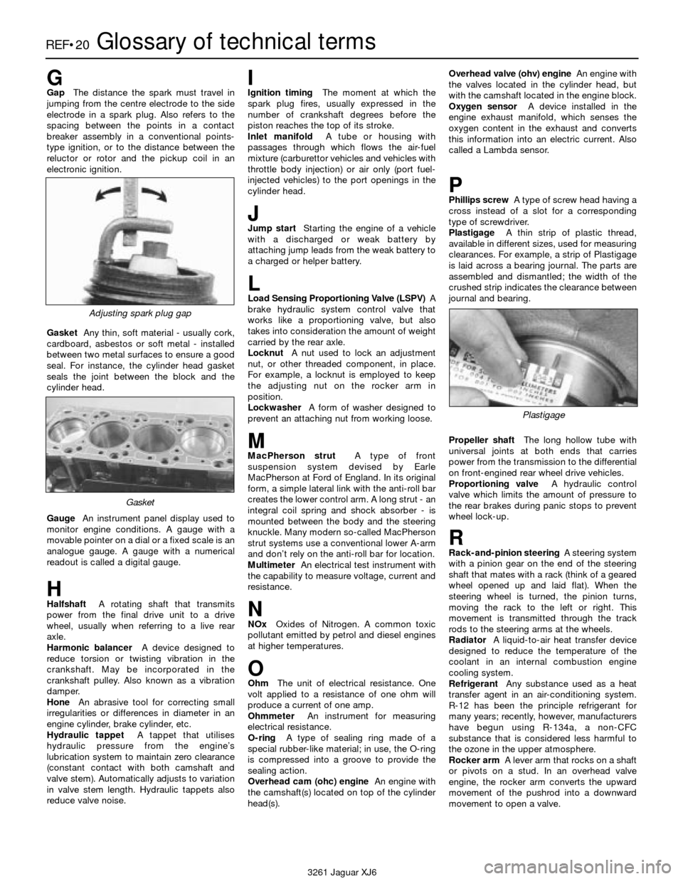
GasketAny thin, soft material - usually cork,
cardboard, asbestos or soft metal - installed
between two metal surfaces to ensure a good
seal. For instance, the cylinder head gasket
seals the joint between the block and the
cylinder head.
GaugeAn instrument panel display used to
monitor engine conditions. A gauge with a
movable pointer on a dial or a fixed scale is an
analogue gauge. A gauge with a numerical
readout is called a digital gauge.
HHalfshaftA rotating shaft that transmits
power from the final drive unit to a drive
wheel, usually when referring to a live rear
axle.
Harmonic balancerA device designed to
reduce torsion or twisting vibration in the
crankshaft. May be incorporated in the
crankshaft pulley. Also known as a vibration
damper.
HoneAn abrasive tool for correcting small
irregularities or differences in diameter in an
engine cylinder, brake cylinder, etc.
Hydraulic tappetA tappet that utilises
hydraulic pressure from the engine’s
lubrication system to maintain zero clearance
(constant contact with both camshaft and
valve stem). Automatically adjusts to variation
in valve stem length. Hydraulic tappets also
reduce valve noise.
IIgnition timingThe moment at which the
spark plug fires, usually expressed in the
number of crankshaft degrees before the
piston reaches the top of its stroke.
Inlet manifoldA tube or housing with
passages through which flows the air-fuel
mixture (carburettor vehicles and vehicles with
throttle body injection) or air only (port fuel-
injected vehicles) to the port openings in the
cylinder head.
JJump startStarting the engine of a vehicle
with a discharged or weak battery by
attaching jump leads from the weak battery to
a charged or helper battery.
LLoad Sensing Proportioning Valve (LSPV)A
brake hydraulic system control valve that
works like a proportioning valve, but also
takes into consideration the amount of weight
carried by the rear axle.
LocknutA nut used to lock an adjustment
nut, or other threaded component, in place.
For example, a locknut is employed to keep
the adjusting nut on the rocker arm in
position.
LockwasherA form of washer designed to
prevent an attaching nut from working loose.
MMacPherson strutA type of front
suspension system devised by Earle
MacPherson at Ford of England. In its original
form, a simple lateral link with the anti-roll bar
creates the lower control arm. A long strut - an
integral coil spring and shock absorber - is
mounted between the body and the steering
knuckle. Many modern so-called MacPherson
strut systems use a conventional lower A-arm
and don’t rely on the anti-roll bar for location.
MultimeterAn electrical test instrument with
the capability to measure voltage, current and
resistance.
NNOxOxides of Nitrogen. A common toxic
pollutant emitted by petrol and diesel engines
at higher temperatures.
OOhmThe unit of electrical resistance. One
volt applied to a resistance of one ohm will
produce a current of one amp.
OhmmeterAn instrument for measuring
electrical resistance.
O-ringA type of sealing ring made of a
special rubber-like material; in use, the O-ring
is compressed into a groove to provide the
sealing action.
Overhead cam (ohc) engineAn engine with
the camshaft(s) located on top of the cylinder
head(s).Overhead valve (ohv) engineAn engine with
the valves located in the cylinder head, but
with the camshaft located in the engine block.
Oxygen sensorA device installed in the
engine exhaust manifold, which senses the
oxygen content in the exhaust and converts
this information into an electric current. Also
called a Lambda sensor.
PPhillips screwA type of screw head having a
cross instead of a slot for a corresponding
type of screwdriver.
PlastigageA thin strip of plastic thread,
available in different sizes, used for measuring
clearances. For example, a strip of Plastigage
is laid across a bearing journal. The parts are
assembled and dismantled; the width of the
crushed strip indicates the clearance between
journal and bearing.
Propeller shaftThe long hollow tube with
universal joints at both ends that carries
power from the transmission to the differential
on front-engined rear wheel drive vehicles.
Proportioning valveA hydraulic control
valve which limits the amount of pressure to
the rear brakes during panic stops to prevent
wheel lock-up.
RRack-and-pinion steeringA steering system
with a pinion gear on the end of the steering
shaft that mates with a rack (think of a geared
wheel opened up and laid flat). When the
steering wheel is turned, the pinion turns,
moving the rack to the left or right. This
movement is transmitted through the track
rods to the steering arms at the wheels.
RadiatorA liquid-to-air heat transfer device
designed to reduce the temperature of the
coolant in an internal combustion engine
cooling system.
RefrigerantAny substance used as a heat
transfer agent in an air-conditioning system.
R-12 has been the principle refrigerant for
many years; recently, however, manufacturers
have begun using R-134a, a non-CFC
substance that is considered less harmful to
the ozone in the upper atmosphere.
Rocker armA lever arm that rocks on a shaft
or pivots on a stud. In an overhead valve
engine, the rocker arm converts the upward
movement of the pushrod into a downward
movement to open a valve.
Adjusting spark plug gap
Plastigage
Gasket