headlights JAGUAR XJ6 1997 2.G Workshop Manual
[x] Cancel search | Manufacturer: JAGUAR, Model Year: 1997, Model line: XJ6, Model: JAGUAR XJ6 1997 2.GPages: 227, PDF Size: 7.2 MB
Page 6 of 227
3261 Jaguar XJ6
0•6Roadside repairs
The following pages are intended to help in dealing with
common roadside emergencies and breakdowns. You will find
more detailed fault finding information at the back of the
manual, and repair information in the main chapters.
If your car won’t start
and the starter motor
doesn’t turn
MIf it’s a model with automatic transmission, make sure the
selector is in ‘P’ or ‘N’.
MOpen the bonnet and make sure that the battery terminals
are clean and tight.
MSwitch on the headlights and try to start the engine. If the
headlights go very dim when you’re trying to start, the
battery is probably flat. Get out of trouble by jump starting
(see next page) using a friend’s car.
If your car won’t start
even though the starter
motor turns as normal
MIs there fuel in the tank?
MIs there moisture on electrical components under the
bonnet? Switch off the ignition, then wipe off any obvious
dampness with a dry cloth. Spray a water-repellent aerosol
product (WD-40 or equivalent) on ignition and fuel system
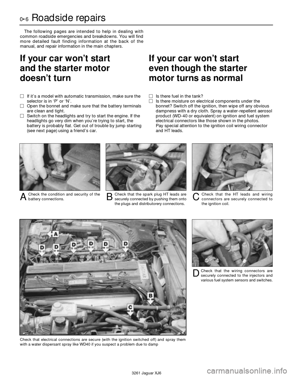
electrical connectors like those shown in the photos.
Pay special attention to the ignition coil wiring connector
and HT leads.
Check the condition and security of the
battery connections.ACheck that the spark plug HT leads are
securely connected by pushing them onto
the plugs and distributorery connections.BCheck that the HT leads and wiring
connectors are securely connected to
the ignition coil.C
Check that the wiring connectors are
securely connected to the injectors and
various fuel system sensors and switches.D
Check that electrical connections are secure (with the ignition switched off) and spray them
with a water dispersant spray like WD40 if you suspect a problem due to damp
Page 100 of 227
headlights or heated rear window and confirm
that the engine rpm decreases at first and
then increases. This check monitors the ISC
motor as it is signalled by the computer to
increase idle speed due to additional
amperage required from the charging system.
As the headlights draw current from the
charging system, the alternator will create
resistance on the belt as it works to produce
the additional energy. If the rpm does not
increase, check the ISC motor.
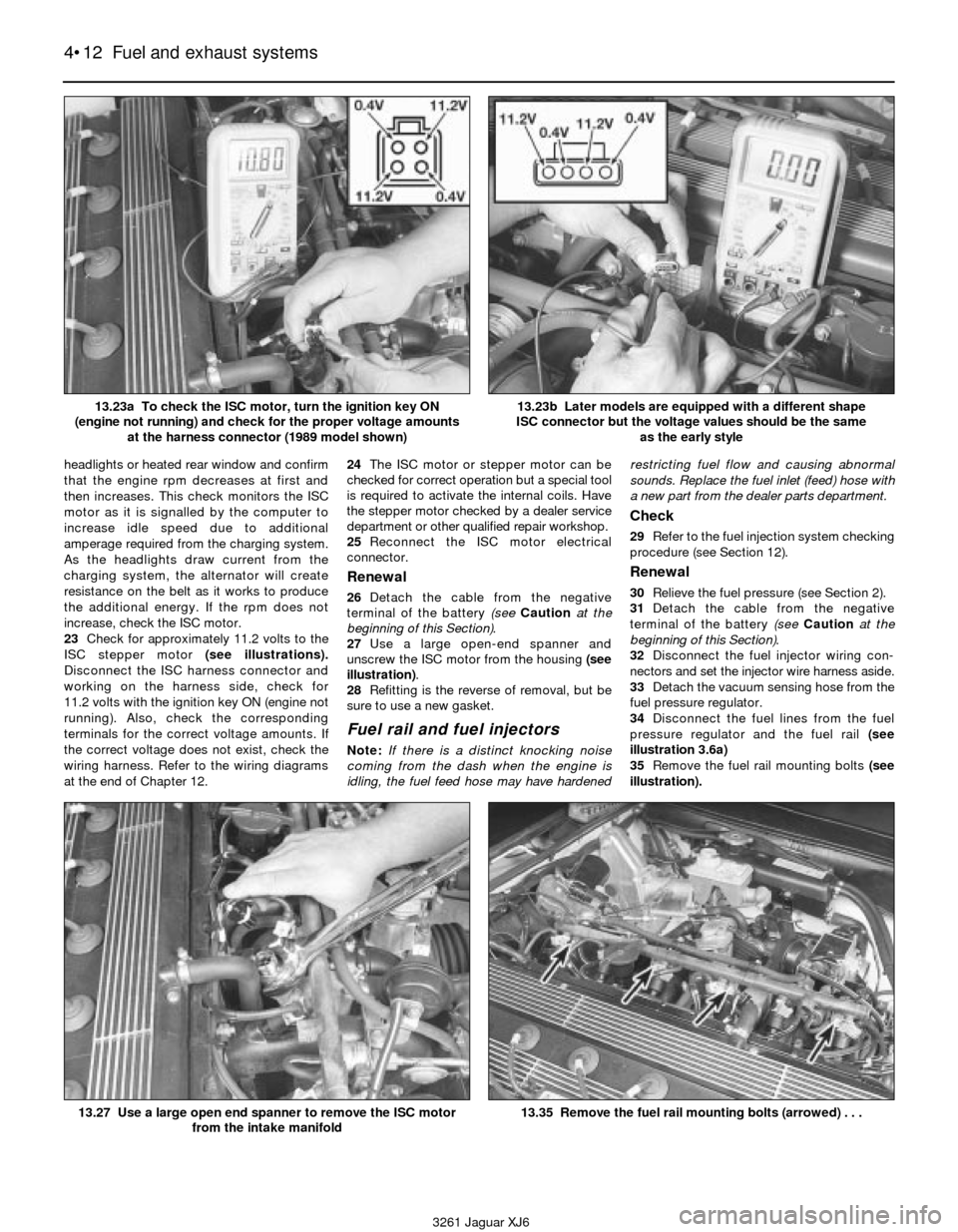
23Check for approximately 11.2 volts to the
ISC stepper motor (see illustrations).
Disconnect the ISC harness connector and
working on the harness side, check for
11.2 volts with the ignition key ON (engine not
running). Also, check the corresponding
terminals for the correct voltage amounts. If
the correct voltage does not exist, check the
wiring harness. Refer to the wiring diagrams
at the end of Chapter 12.24The ISC motor or stepper motor can be
checked for correct operation but a special tool
is required to activate the internal coils. Have
the stepper motor checked by a dealer service
department or other qualified repair workshop.
25Reconnect the ISC motor electrical
connector.
Renewal
26Detach the cable from the negative
terminal of the battery (see Cautionat the
beginning of this Section).
27Use a large open-end spanner and
unscrew the ISC motor from the housing (see
illustration).
28Refitting is the reverse of removal, but be
sure to use a new gasket.
Fuel rail and fuel injectors
Note:If there is a distinct knocking noise
coming from the dash when the engine is
idling, the fuel feed hose may have hardenedrestricting fuel flow and causing abnormal
sounds. Replace the fuel inlet (feed) hose with
a new part from the dealer parts department.
Check
29Refer to the fuel injection system checking
procedure (see Section 12).
Renewal
30Relieve the fuel pressure (see Section 2).
31Detach the cable from the negative
terminal of the battery (see Cautionat the
beginning of this Section).
32Disconnect the fuel injector wiring con-
nectors and set the injector wire harness aside.
33Detach the vacuum sensing hose from the
fuel pressure regulator.
34Disconnect the fuel lines from the fuel
pressure regulator and the fuel rail (see
illustration 3.6a)
35Remove the fuel rail mounting bolts (see
illustration).
4•12 Fuel and exhaust systems
3261 Jaguar XJ6 13.23a To check the ISC motor, turn the ignition key ON
(engine not running) and check for the proper voltage amounts
at the harness connector (1989 model shown)
13.23b Later models are equipped with a different shape
ISC connector but the voltage values should be the same
as the early style
13.27 Use a large open end spanner to remove the ISC motor
from the intake manifold13.35 Remove the fuel rail mounting bolts (arrowed) . . .
Page 108 of 227
model but the designations are the same.
Refer to the wiring diagrams at the end of
Chapter 12.
f) Start the engine and check the alternator
for abnormal noises (a shrieking or
squealing sound indicates a bad bushing).
g) Check the specific gravity of the battery
electrolyte. If it’s low, charge the battery
(doesn’t apply to maintenance free
batteries).
h) Make sure that the battery is fully charged
(one bad cell in a battery can cause
overcharging by the alternator).
i) Disconnect the battery cables (negative
first, then positive). Caution:If the stereo
in your vehicle is equipped with an anti-
theft system, make sure you have the
correct activation code before
disconnecting the battery. Inspect the
battery posts and the cable clamps for
corrosion. Clean them thoroughly if
necessary (see Chapter 1). Reconnect the
positive cable, then the negative cable.
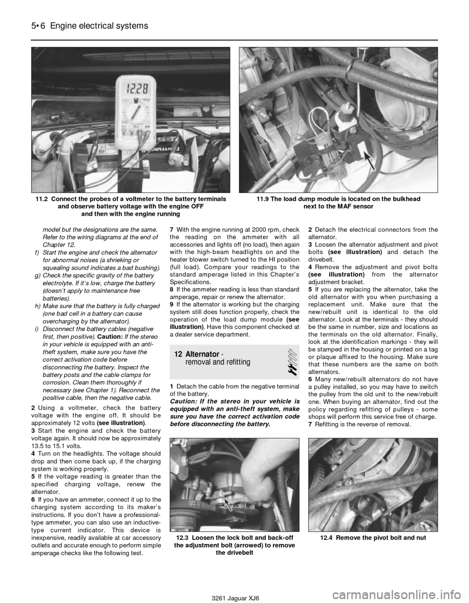
2Using a voltmeter, check the battery
voltage with the engine off. It should be
approximately 12 volts (see illustration).
3Start the engine and check the battery
voltage again. It should now be approximately
13.5 to 15.1 volts.
4Turn on the headlights. The voltage should
drop and then come back up, if the charging
system is working properly.
5If the voltage reading is greater than the
specified charging voltage, renew the
alternator.
6If you have an ammeter, connect it up to the
charging system according to its maker’s
instructions. If you don’t have a professional-
type ammeter, you can also use an inductive-
type current indicator. This device is
inexpensive, readily available at car accessory
outlets and accurate enough to perform simple
amperage checks like the following test.7With the engine running at 2000 rpm, check
the reading on the ammeter with all
accessories and lights off (no load), then again
with the high-beam headlights on and the
heater blower switch turned to the HI position
(full load). Compare your readings to the
standard amperage listed in this Chapter’s
Specifications.
8If the ammeter reading is less than standard
amperage, repair or renew the alternator.
9If the alternator is working but the charging
system still does function properly, check the
operation of the load dump module (see
illustration). Have this component checked at
a dealer service department.
12 Alternator-
removal and refitting
2
1Detach the cable from the negative terminal
of the battery.
Caution: If the stereo in your vehicle is
equipped with an anti-theft system, make
sure you have the correct activation code
before disconnecting the battery.2Detach the electrical connectors from the
alternator.
3Loosen the alternator adjustment and pivot
bolts (see illustration) and detach the
drivebelt.
4Remove the adjustment and pivot bolts
(see illustration)from the alternator
adjustment bracket.
5If you are replacing the alternator, take the
old alternator with you when purchasing a
replacement unit. Make sure that the
new/rebuilt unit is identical to the old
alternator. Look at the terminals - they should
be the same in number, size and locations as
the terminals on the old alternator. Finally,
look at the identification markings - they will
be stamped in the housing or printed on a tag
or plaque affixed to the housing. Make sure
that these numbers are the same on both
alternators.
6Many new/rebuilt alternators do not have
a pulley installed, so you may have to switch
the pulley from the old unit to the new/rebuilt
one. When buying an alternator, find out the
policy regarding refitting of pulleys - some
shops will perform this service free of charge.
7Refitting is the reverse of removal.
5•6 Engine electrical systems
12.3 Loosen the lock bolt and back-off
the adjustment bolt (arrowed) to remove
the drivebelt12.4 Remove the pivot bolt and nut
3261 Jaguar XJ6 11.2 Connect the probes of a voltmeter to the battery terminals
and observe battery voltage with the engine OFF
and then with the engine running
11.9 The load dump module is located on the bulkhead
next to the MAF sensor
Page 154 of 227

3Remove two bumper retaining bolts located
on the bottom side of the bumper (see
illustration). Pull the bumper assembly out
and away from the vehicle to remove it.
4Refitting is the reverse of removal.
15 Front wing-
removal and refitting
3
1Loosen the front wheel nuts. Raise the
vehicle, support it securely on axle stands and
remove the front wheel.
2Remove the front bumper assembly (see
Section 14).
3Remove the front spoiler (see Section 13).4Detach the inner wing splash shield (see
illustration).
5On 1988 and 1989 models, remove the
coolant overflow reservoir located behind the
splash shield (see Chapter 3).
6On models with round headlights, remove
the headlight bezel. On models with
composite headlights (1992 Vanden Plas, all
1993 and later models), remove the headlight
(see Chapter 12).
7Remove the wing mounting bolts and nuts
(see illustrations).
8Detach the wing. It’s a good idea to have an
assistant support the wing while it’s being
moved away from the vehicle to prevent
damage to the surrounding body panels.
9Refitting is the reverse of removal.
16 Boot lid- removal,
refitting and adjustment
2
Note:The boot lid is heavy and somewhat
awkward to remove and refit - at least two
people should perform this procedure.
Removal and refitting
1Open the boot lid and cover the edges of
the boot compartment with pads or cloths to
protect the painted surfaces when the lid is
removed.
2Disconnect any cables or wire harness
connectors attached to the boot lid that would
interfere with removal.
3Make alignment marks around the hinge
mounting bolts with a marking pen.
4While an assistant supports the boot lid,
remove the lid-to-hinge bolts on both sides
and lift it off(see illustration).
5Refitting is the reverse of removal. Note:
When refitting the boot lid, align the lid-to-
hinge bolts with the marks made during
removal.
Adjustment
6Fore-and-aft and side-to-side adjustment
of the boot lid is done by moving the bonnet in
relation to the hinge plate after loosening the
bolts or nuts.
7Scribe a line around the entire hinge plate
as described earlier in this section so you can
judge the amount of movement.
11•6 Bodywork and fittings
14.3 Remove the two retaining bolts from
the bottom of the bumper, then remove the
bumper from the vehicle15.4 Remove the bolts (arrowed) securing
the inner wing splash shield15.7a Detach the wing retaining bolts
(arrowed) at the front of the wing
15.7c Working in the wheel opening,
remove the wing-to-rocker panel bolt
(arrowed)
15.7d Remove the wing-to-door pillar bolt
(arrow; lower bolt not visible)15.7e Detach the bolts along the
top of the wing
3261 Jaguar XJ6
15.7b Remove the wing-to-radiator
support bolt (arrowed)
16.4 With the help of an assistant to hold
the boot lid, remove the retaining bolts and
lift off the boot lid
Page 163 of 227
3261 Jaguar XJ6
12
Chapter 12
Body electrical system
1 General information
The electrical system is a 12-volt, negative
earth type. Power for the lights and all
electrical accessories is supplied by a
lead/acid-type battery which is charged by
the alternator.
This Chapter covers repair and service
procedures for the various electrical
components not associated with the engine.
Information on the battery, alternator,
distributor and starter motor will be found in
Chapter 5.
It should be noted that when portions of the
electrical system are serviced, the cable
should be disconnected from the negative
battery terminal to prevent electrical shorts
and/or fires.
2 Electrical fault finding-
general information
A typical electrical circuit consists of an
electrical component, any switches, relays,
motors, fuses, fusible links, in-line fuses or
circuit breakers related to that component
and the wiring and electrical connectors that
link the component to both the battery andthe chassis. To help you pinpoint an electrical
circuit problem, wiring diagrams are included
at the end of this Chapter.
Before tackling any troublesome electrical
circuit, first study the appropriate wiring
diagrams to get a complete understanding of
what makes up that individual circuit. Trouble
spots, for instance, can often be narrowed
down by noting if other components related to
the circuit are operating properly. If several
components or circuits fail at one time,
chances are the problem is in a fuse or earth
connection, because several circuits are often
routed through the same fuse and earth
connections.
Electrical problems usually stem from
simple causes, such as loose or corroded
connections, a blown fuse, a melted fusible
link or a bad relay. Visually inspect the
condition of all fuses, wires and connections
in a problem circuit before diagnosing it.
If testing instruments are going to be
utilised, use the diagrams to plan ahead of
time where you will make the necessary
connections in order to accurately pinpoint
the trouble spot.
The basic tools needed for electrical fault
finding include a circuit tester or voltmeter (a
12-volt bulb with a set of test leads can also
be used), a continuity tester, which includes a
bulb, battery and set of test leads, and a
jumper wire, preferably with a circuit breaker
incorporated, which can be used to bypasselectrical components. Before attempting to
locate a problem with test instruments,
use the wiring diagram(s) to decide where to
make the connections.
Voltage checks
Voltage checks should be performed if a
circuit is not functioning properly. Connect
one lead of a circuit tester to either the
negative battery terminal or a known good
earth. Connect the other lead to a electrical
connector in the circuit being tested,
preferably nearest to the battery or fuse. If the
bulb of the tester lights, voltage is present,
which means that the part of the circuit
between the electrical connector and the
battery is problem free. Continue checking the
rest of the circuit in the same fashion. When
you reach a point at which no voltage is
present, the problem lies between that point
and the last test point with voltage. Most of
the time the problem can be traced to a loose
connection. Note:Keep in mind that some
circuits receive voltage only when the ignition
key is in the Accessory or Run position.
Finding a short
One method of finding shorts in a circuit is
to remove the fuse and connect a test light or
voltmeter in its place. There should be no
voltage present in the circuit. Move the wiring
harness from side to side while watching the
test light. If the bulb goes on, there is a short Airbag system - general information . . . . . . . . . . . . . . . . . . . . . . . . . 28
Bulb renewal . . . . . . . . . . . . . . . . . . . . . . . . . . . . . . . . . . . . . . . . . . . 21
Central locking system - description and check . . . . . . . . . . . . . . . . 25
Circuit breakers - general information . . . . . . . . . . . . . . . . . . . . . . . . 5
Cruise control system - description and check . . . . . . . . . . . . . . . . . 23
Direction indicators/hazard flashers - general information . . . . . . . . 7
Electric aerial - removal and refitting . . . . . . . . . . . . . . . . . . . . . . . . . 14
Electric side view mirrors - description and check . . . . . . . . . . . . . . 26
Electric sunroof - description and check . . . . . . . . . . . . . . . . . . . . . . 27
Electric window system - description and check . . . . . . . . . . . . . . . 24
Electrical fault finding - general information . . . . . . . . . . . . . . . . . . . 2
Fuel, oil and temperature gauges - check . . . . . . . . . . . . . . . . . . . . . 11
Fuses - general information . . . . . . . . . . . . . . . . . . . . . . . . . . . . . . . . 3
General information . . . . . . . . . . . . . . . . . . . . . . . . . . . . . . . . . . . . . . 1
Headlight housing (1992 to 1994 models) - removal and refitting . . . 19Headlights - adjustment . . . . . . . . . . . . . . . . . . . . . . . . . . . . . . . . . . 18
Headlights - renewal . . . . . . . . . . . . . . . . . . . . . . . . . . . . . . . . . . . . . 17
Heated rear window - check and repair . . . . . . . . . . . . . . . . . . . . . . 16
Horn - check and renewal . . . . . . . . . . . . . . . . . . . . . . . . . . . . . . . . . 20
Ignition switch and key lock cylinder - removal and refitting . . . . . . 9
Inertia switch - description and check . . . . . . . . . . . . . . . . . . . . . . . . 22
In-line fuses - general information . . . . . . . . . . . . . . . . . . . . . . . . . . . 4
Instrument cluster - removal and refitting . . . . . . . . . . . . . . . . . . . . . 12
Instrument panel switches - removal and refitting . . . . . . . . . . . . . . 10
Radio and speakers - removal and refitting . . . . . . . . . . . . . . . . . . . 13
Relays - general information and testing . . . . . . . . . . . . . . . . . . . . . . 6
Steering column switches - removal and refitting . . . . . . . . . . . . . . . 8
Windscreen wiper motor - removal and refitting . . . . . . . . . . . . . . . . 15
Wiring diagrams - general information . . . . . . . . . . . . . . . . . . . . . . . 29
12•1
Contents
Easy,suitable for
novice with little
experienceFairly easy,suitable
for beginner with
some experienceFairly difficult,
suitable for competent
DIY mechanic
Difficult,suitable for
experienced DIY
mechanicVery difficult,
suitable for expert DIY
or professional
Degrees of difficulty
54321
Page 165 of 227
wash system, radio memory and the ABS
main feed and pump circuits.
In-line fuses are located through out the
vehicle depending on the year, make and
model. Consult the wiring diagrams at the end
of this Chapter for further information.
In-line fuses also have a blade terminal
design, which allow fingertip removal and
renewal. If an electrical component fails,
always check the fuse first. A blown fuse is
easily identified through the clear plastic
body. Inspect the element for evidence of
damage (see illustration 3.3).
Be sure to renew blown fuses with the
correct type. Fuses are usually colour-coded
to indicate their rating. Fuses of different
ratings are physically interchangeable, but
only fuses of the proper rating should be
used. Replacing a fuse with one of a different
value than specified is not recommended.
Each electrical circuit needs a specific
amount of protection. The amperage value of
each fuse is moulded into the fuse body.If the renewal fuse immediately fails, don’t
renew it again until the cause of the problem
is isolated and corrected. Don’t substitute
anything else for the fuse. In most cases, this
will be a short circuit in the wiring caused by a
broken or deteriorated wire.
5 Circuit breakers-
general information
Circuit breakers generally protect
components such as electric windows, central
locking and headlights. On some models the
circuit breaker resets itself automatically, so
an electrical overload in the circuit will cause it
to fail momentarily, then come back on. If the
circuit doesn’t come back on, check it
immediately. Once the condition is corrected,
the circuit breaker will resume its normal
function. Some circuit breakers have a button
on top and must be reset manually.To test a circuit breaker, use an ohmmeter
to check continuity between the terminals. A
reading of zero to 1.0 ohms indicates a good
circuit breaker. An open circuit reading on the
meter indicates a bad circuit breaker.
6 Relays- general information
and testing
2
General information
Several electrical accessories in the vehicle,
such as the fuel injection system, electric
windows, central locking, etc, use relays to
transmit the electrical signal to the component.
Relays use a low-current circuit (the control
circuit) to open and close a high-current circuit
(the power circuit). If the relay is defective, that
component will not operate properly. The
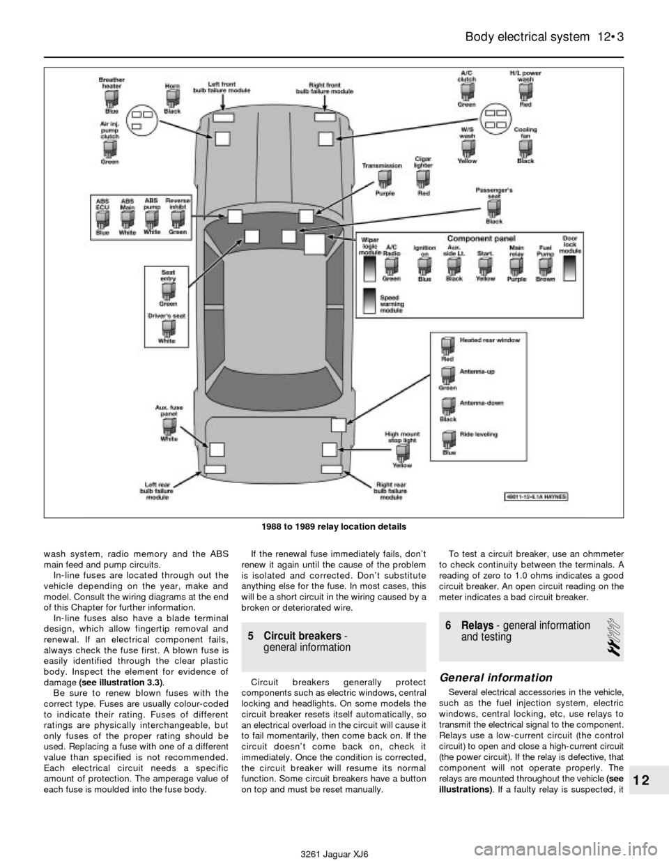
relays are mounted throughout the vehicle (see
illustrations). If a faulty relay is suspected, it
Body electrical system 12•3
12
3261 Jaguar XJ6 1988 to 1989 relay location details
Page 171 of 227

6If the voltage is 6 volts, the element is okay
(there is no break). If the voltage is 12 volts,
the element is broken between the centre
of the element and the positive end. If the
voltage is 0 volts the element is broken
between the centre of the element and earth.
7To find the break, place the voltmeter
positive lead against the defogger positive
terminal. Place the voltmeter negative lead
with the foil strip against the heating element
at the positive terminal end and slide it toward
the negative terminal end. The point at which
the voltmeter deflects from zero to several
volts is the point at which the heating element
is broken (see illustration).
Repair
8Repair the break in the element using a
repair kit specifically recommended for this
purpose.
9Prior to repairing a break, turn off the system
and allow it to cool off for a few minutes.
10Lightly buff the element area with fine
steel wool, then clean it thoroughly with
rubbing alcohol.
11Use masking tape to mask off the area
being repaired.
12Thoroughly mix the epoxy, following the
instructions provided with the repair kit.
13Apply the epoxy material to the slit in the
masking tape, overlapping the undamaged
area about 3/4-inch on either end (see
illustration).
14Allow the repair to cure for 24 hours before
removing the tape and using the system.
17 Headlights- renewal
1
Warning: Later models are
equipped with halogen gas-filled
headlight bulbs which are underpressure and may shatter if the surface is
damaged or the bulb is dropped. Wear eye
protection and handle the bulbs carefully,
grasping only the base whenever possible.
Do not touch the surface of the bulb with
your fingers because the oil from your skin
could cause it to overheat and fail
prematurely. If you do touch the bulb
surface, clean it with rubbing alcohol.
Sealed beam units
1Remove the radiator grille (see Chapter 11).
2Detach the headlight bezel trim cover (see
illustration).
3Remove the headlight bezel (see
illustrations).
4Remove the screws which secure the
retaining ring and withdraw the ring. Support
the light as this is done (see illustration).
Body electrical system 12•9
12
16.13 Apply masking tape to the inside of
the window at the damaged area, then
brush on the special conductive coating17.2 Remove the screws (arrowed) and
detach the headlight bezel trim cover
17.3a Remove the two retaining screws
at the top and the one in the grille opening
(arrowed)17.3b The retaining screw at the
outside lower corner can be accessed
from under the bumper
3261 Jaguar XJ6 16.5 To determine if a heating element has broken, check the
voltage at the centre of each element. If the voltage is 6-volts, the
element is unbroken; if the voltage is 12-volts, the element is
broken between the centre and the positive end. If there is no
voltage, the element is broken between the centre and earth
16.7 To find the break, place the voltmeter positive lead against
the heated window positive terminal, place the voltmeter negative
lead with the foil strip against the heating element at the positive
terminal end and slide it toward the negative terminal end -
the point at which the voltmeter reading changes abruptly is the
point at which the element is broken
Page 172 of 227
5Pull the headlight out slightly and
disconnect the electrical connector from the
rear of the light, then remove the light from the
vehicle.
6To refit, position the new unit close enough
to connect the electrical connector. Make
sure that the numbers moulded into the lens
are at the top.
7Refit and tighten the retaining ring. Test the
headlight operation.
8The remainder of the refitting is the reverse
of removal.
Halogen gas-filled bulbs
9Disconnect the electrical connector from
the bulb assembly. Rotate the headlight bulb
connector 1/4-turn anti-clockwise (viewed
from the rear) (see illustration).
10Withdraw the bulb assembly from the
headlight housing.
11Without touching the glass with your bare
fingers (see the Warningat the start of the
Section), insert the new bulb assembly into
the headlight housing and rotate the bulb
socket 1/4-turn clockwise to refit it.
12Plug in the electrical connector and test
headlight operation.
18 Headlights- adjustment
5
Note:The following procedure is intended for
emergency use only, and we strongly
recommend that the headlight aim is only
checked using optical beam-setting
equipment. It is important that the headlights
are aimed correctly. If adjusted incorrectly
they could blind the driver of an oncoming
vehicle and cause a serious accident or
seriously reduce your ability to see the road.
The headlights should be checked for proper
aim every 12 months and any time a new
headlight is installed or front end body work is
performed.
1Adjustment should be made with the
vehicle sitting level, the petrol tank half-full
and no unusually heavy load in the vehicle.2Early models with sealed beam headlights
have four adjusting knobs protruding through
the backside of the radiator support. The
vertical (up and down) adjustment knobs are
located above the headlight and the horizontal
(left to right) adjusting knobs are located
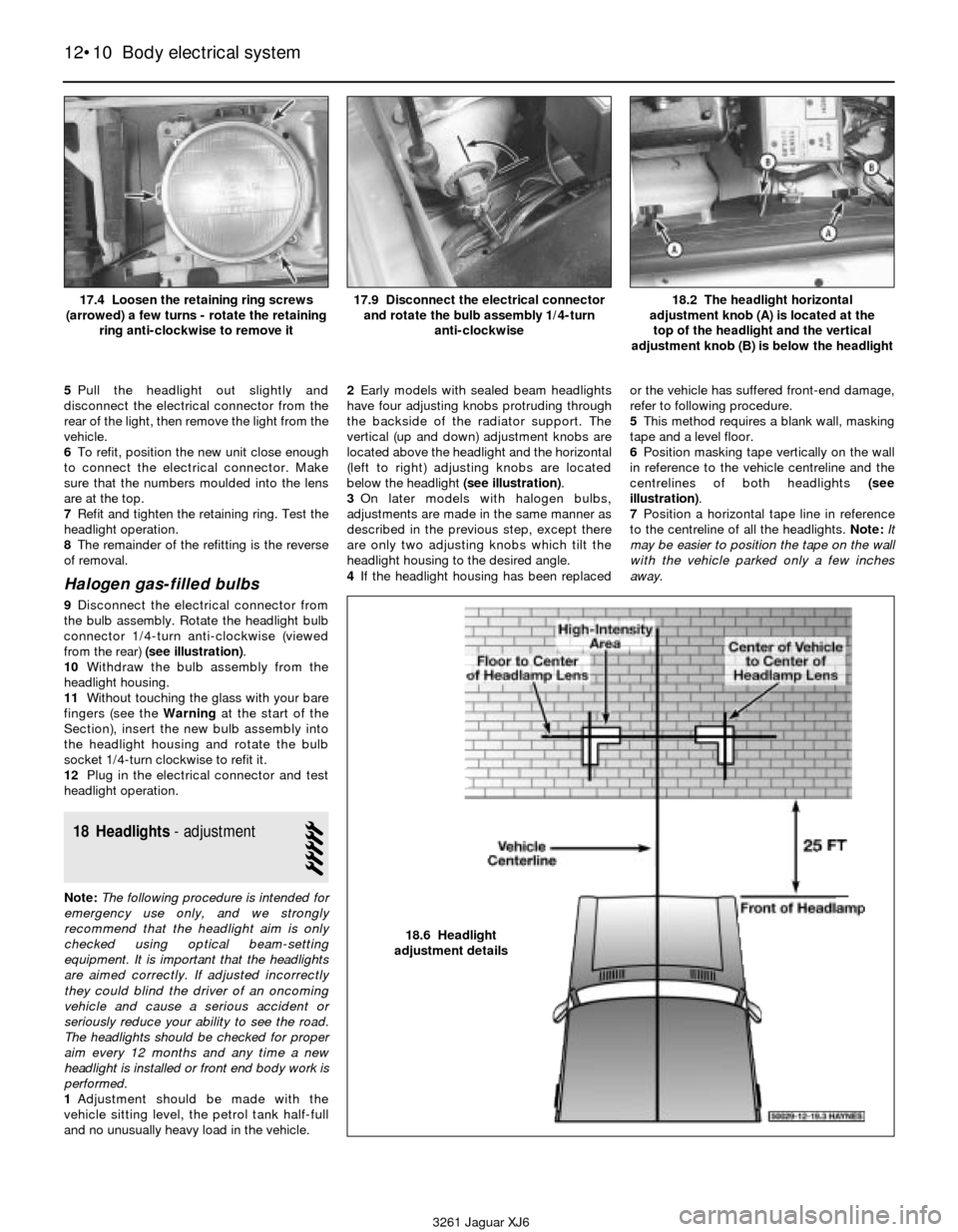
below the headlight (see illustration).
3On later models with halogen bulbs,
adjustments are made in the same manner as
described in the previous step, except there
are only two adjusting knobs which tilt the
headlight housing to the desired angle.
4If the headlight housing has been replacedor the vehicle has suffered front-end damage,
refer to following procedure.
5This method requires a blank wall, masking
tape and a level floor.
6Position masking tape vertically on the wall
in reference to the vehicle centreline and the
centrelines of both headlights (see
illustration).
7Position a horizontal tape line in reference
to the centreline of all the headlights. Note:It
may be easier to position the tape on the wall
with the vehicle parked only a few inches
away.
12•10 Body electrical system
3261 Jaguar XJ618.2 The headlight horizontal
adjustment knob (A) is located at the
top of the headlight and the vertical
adjustment knob (B) is below the headlight
17.4 Loosen the retaining ring screws
(arrowed) a few turns - rotate the retaining
ring anti-clockwise to remove it17.9 Disconnect the electrical connector
and rotate the bulb assembly 1/4-turn
anti-clockwise
18.6 Headlight
adjustment details
Page 173 of 227
8Adjustment should be made with the
vehicle parked 25 feet from the wall, sitting
level, the petrol tank half-full and no unusually
heavy load in the vehicle.
9Starting with the low beam adjustment,
position the high intensity zone so it is two
inches below the horizontal line and two
inches to the right of the headlight vertical
line. Adjustments are made by turning the
knobs located behind the headlight housings
(see illustration 18.2).
10With the high beams on, the high intensity
zone should be vertically centred with the
exact centre just below the horizontal line.
Note:It may not be possible to position the
headlight aim exactly for both high and low
beams. If a compromise must be made, keep
in mind that the low beams are the most used
and have the greatest effect on safety.
11Have the headlights adjusted by a dealer
service department or service station at the
earliest opportunity.
19 Headlight housing
(1992 to 1994 models)-
removal and refitting
1
Warning: These vehicles are
equipped with halogen gas-filled
headlight bulbs which are under
pressure and may shatter if the
surface is damaged or the bulb is dropped.
Wear eye protection and handle the bulbs
carefully, grasping only the base whenever
possible. Do not touch the surface of the
bulb with your fingers because the oil from
your skin could cause it to overheat and
fail prematurely. If you do touch the bulb
surface, clean it with rubbing alcohol.
1Remove the headlight bulb (Section 17).
2Remove the retaining nuts, detach the
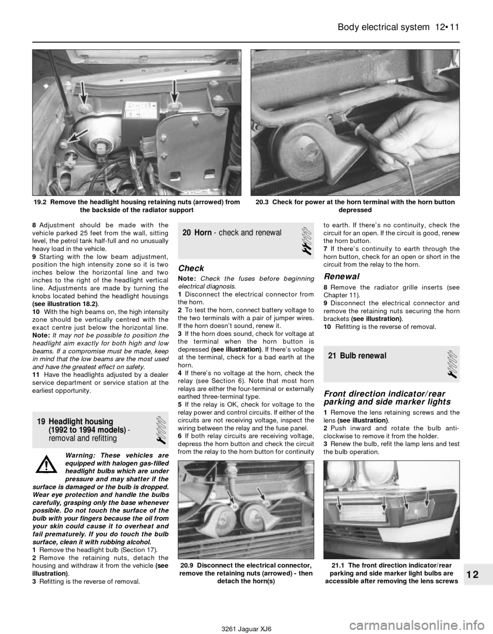
housing and withdraw it from the vehicle (see
illustration).
3Refitting is the reverse of removal.
20 Horn- check and renewal
2
Check
Note:Check the fuses before beginning
electrical diagnosis.
1Disconnect the electrical connector from
the horn.
2To test the horn, connect battery voltage to
the two terminals with a pair of jumper wires.
If the horn doesn’t sound, renew it.
3If the horn does sound, check for voltage at
the terminal when the horn button is
depressed (see illustration). If there’s voltage
at the terminal, check for a bad earth at the
horn.
4If there’s no voltage at the horn, check the
relay (see Section 6). Note that most horn
relays are either the four-terminal or externally
earthed three-terminal type.
5If the relay is OK, check for voltage to the
relay power and control circuits. If either of the
circuits are not receiving voltage, inspect the
wiring between the relay and the fuse panel.
6If both relay circuits are receiving voltage,
depress the horn button and check the circuit
from the relay to the horn button for continuityto earth. If there’s no continuity, check the
circuit for an open. If the circuit is good, renew
the horn button.
7If there’s continuity to earth through the
horn button, check for an open or short in the
circuit from the relay to the horn.Renewal
8Remove the radiator grille inserts (see
Chapter 11).
9Disconnect the electrical connector and
remove the retaining nuts securing the horn
brackets (see illustration).
10Refitting is the reverse of removal.
21 Bulb renewal
1
Front direction indicator/rear
parking and side marker lights
1Remove the lens retaining screws and the
lens (see illustration).
2Push inward and rotate the bulb anti-
clockwise to remove it from the holder.
3Renew the bulb, refit the lamp lens and test
the bulb operation.
Body electrical system 12•11
12
20.9 Disconnect the electrical connector,
remove the retaining nuts (arrowed) - then
detach the horn(s)21.1 The front direction indicator/rear
parking and side marker light bulbs are
accessible after removing the lens screws
3261 Jaguar XJ6 19.2 Remove the headlight housing retaining nuts (arrowed) from
the backside of the radiator support
20.3 Check for power at the horn terminal with the horn button
depressed
Page 210 of 227

3261 Jaguar XJ6
MOT test checksREF•9
Seat belts and seats
Note: The following checks are applicable to
all seat belts, front and rear.
MExamine the webbing of all the belts
(including rear belts if fitted) for cuts, serious
fraying or deterioration. Fasten and unfasten
each belt to check the buckles. If applicable,
check the retracting mechanism. Check the
security of all seat belt mountings accessible
from inside the vehicle.
MThe front seats themselves must be
securely attached and the backrests must
lock in the upright position.
Doors
MBoth front doors must be able to be opened
and closed from outside and inside, and must
latch securely when closed.
Vehicle identification
MNumber plates must be in good condition,
secure and legible, with letters and numbers
correctly spaced – spacing at (A) should be
twice that at (B).
MThe VIN plate and/or homologation plate
must be legible.
Electrical equipment
MSwitch on the ignition and check the
operation of the horn.
MCheck the windscreen washers and wipers,
examining the wiper blades; renew damaged
or perished blades. Also check the operation
of the stop-lights.
MCheck the operation of the sidelights and
number plate lights. The lenses and reflectors
must be secure, clean and undamaged.
MCheck the operation and alignment of the
headlights. The headlight reflectors must not
be tarnished and the lenses must be
undamaged.
MSwitch on the ignition and check the
operation of the direction indicators (including
the instrument panel tell-tale) and the hazard
warning lights. Operation of the sidelights and
stop-lights must not affect the indicators - if it
does, the cause is usually a bad earth at the
rear light cluster.
MCheck the operation of the rear foglight(s),
including the warning light on the instrument
panel or in the switch.
Footbrake
MExamine the master cylinder, brake pipes
and servo unit for leaks, loose mountings,
corrosion or other damage.
MThe fluid reservoir must be secure and the
fluid level must be between the upper (A) and
lower (B) markings.MInspect both front brake flexible hoses for
cracks or deterioration of the rubber. Turn the
steering from lock to lock, and ensure that the
hoses do not contact the wheel, tyre, or any
part of the steering or suspension mechanism.
With the brake pedal firmly depressed, check
the hoses for bulges or leaks under pressure.
Steering and suspension
MHave your assistant turn the steering wheel
from side to side slightly, up to the point where
the steering gear just begins to transmit this
movement to the roadwheels. Check for
excessive free play between the steering
wheel and the steering gear, indicating wear or
insecurity of the steering column joints, the
column-to-steering gear coupling, or the
steering gear itself.
MHave your assistant turn the steering wheel
more vigorously in each direction, so that the
roadwheels just begin to turn. As this is done,
examine all the steering joints, linkages,
fittings and attachments. Renew any
component that shows signs of wear or
damage. On vehicles with power steering,
check the security and condition of the
steering pump, drivebelt and hoses.
MCheck that the vehicle is standing level,
and at approximately the correct ride height.
Shock absorbers
MDepress each corner of the vehicle in turn,
then release it. The vehicle should rise and
then settle in its normal position. If the vehicle
continues to rise and fall, the shock absorber
is defective. A shock absorber which has
seized will also cause the vehicle to fail.
2Checks carried out
WITH THE VEHICLE ON THE
GROUND