service indicator JAGUAR XJ6 1997 2.G Workshop Manual
[x] Cancel search | Manufacturer: JAGUAR, Model Year: 1997, Model line: XJ6, Model: JAGUAR XJ6 1997 2.GPages: 227, PDF Size: 7.2 MB
Page 9 of 227
3261 Jaguar XJ6
Roadside repairs0•9
When all else fails, you may find yourself
having to get a tow home – or of course you
may be helping somebody else. Long-distance
recovery should only be done by a garage or
breakdown service. For shorter distances, DIY
towing using another car is easy enough, but
observe the following points:
MUse a proper tow-rope – they are not
expensive. The vehicle being towed must
display an ‘ON TOW’ sign in its rear window.
MAlways turn the ignition key to the ‘on’
position when the vehicle is being towed, so
that the steering lock is released, and that the
direction indicator and brake lights will work.
MOnly attach the tow-rope to the towing
eyes provided. On some models with energy-
absorbing bumpers there are no front towing
eyes; on these vehicles the tow-rope shouldbe attached around the rear arm of the lower
control arm so that the rope passes on the
inside of the coil spring.
MBefore being towed, release the handbrake
and select neutral on the transmission.
MNote that greater-than-usual pedal
pressure will be required to operate the
brakes, since the vacuum servo unit is only
operational with the engine running.
MOn models with power steering, greater-
than-usual steering effort will also be required.
MThe driver of the car being towed must
keep the tow-rope taut at all times to avoid
snatching.
MMake sure that both drivers know the route
before setting off.
MOnly drive at moderate speeds and keep
the distance towed to a minimum. Drivesmoothly and allow plenty of time for slowing
down at junctions.
MOn models with automatic transmission,
special precautions apply. If in doubt, do not
tow, or transmission damage may result.
Caution: On models with automatic
transmission, if the vehicle is to be towed
with its rear wheels on the ground, and
extra 1.7 litres of fluid should be added to
the transmission, prior to towing (this extra
fluid must be drained before driving the
vehicle). Even with the extra fluid added to
the transmission, do not tow the vehicle at
speeds in excess of 30 mph (50 kmh) or for
a distance of greater than 15 miles (25 km).
If towing speed/distance are to exceed
these limits, then the vehicle must be
towed with its rear wheels off the ground.
Towing
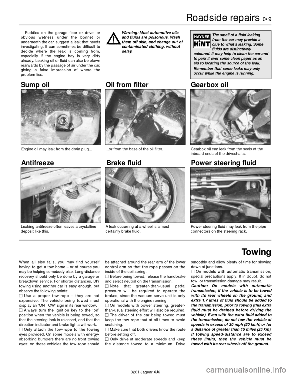
Puddles on the garage floor or drive, or
obvious wetness under the bonnet or
underneath the car, suggest a leak that needs
investigating. It can sometimes be difficult to
decide where the leak is coming from,
especially if the engine bay is very dirty
already. Leaking oil or fluid can also be blown
rearwards by the passage of air under the car,
giving a false impression of where the
problem lies.Warning: Most automotive oils
and fluids are poisonous. Wash
them off skin, and change out of
contaminated clothing, without
delay.The smell of a fluid leaking
from the car may provide a
clue to what’s leaking. Some
fluids are distinctively
coloured. It may help to clean the car and
to park it over some clean paper as an
aid to locating the source of the leak.
Remember that some leaks may only
occur while the engine is running.
Sump oil Gearbox oil
Brake fluid
Power steering fluid
Oil from filter
Antifreeze
Engine oil may leak from the drain plug......or from the base of the oil filter.
Leaking antifreeze often leaves a crystalline
deposit like this.Gearbox oil can leak from the seals at the
inboard ends of the driveshafts.
A leak occurring at a wheel is almost
certainly brake fluid.Power steering fluid may leak from the pipe
connectors on the steering rack.
Page 25 of 227
5 Power hydraulic system
fluid level check
1
Caution: Use only Castrol or Jaguar
hydraulic system mineral oil (HSMO) in the
power hydraulic system (available at
Jaguar dealer service departments).
1The power hydraulic system controls the ride
levelling and the brake servo systems. The
fluid reservoir also supplies the power
steering system on some models. The level
of the fluid should be carefully maintained. Low
fluid levels can adversely affect the riding and
braking capabilities of your vehicle. The power
hydraulic system fluid reservoir is located on
the right inner wing of the engine compartment.
1988 and 1989 models
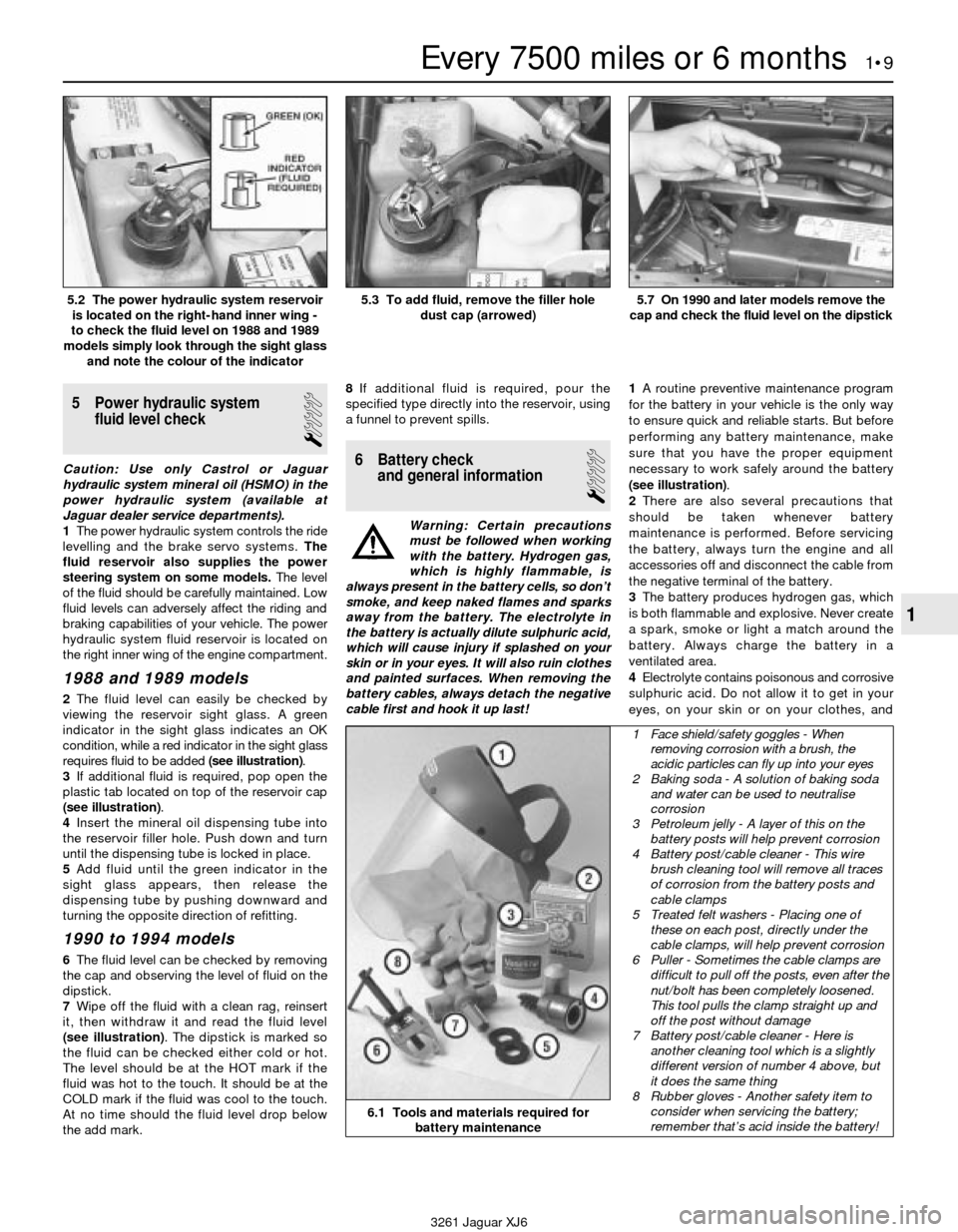
2The fluid level can easily be checked by
viewing the reservoir sight glass. A green
indicator in the sight glass indicates an OK
condition, while a red indicator in the sight glass
requires fluid to be added (see illustration).
3If additional fluid is required, pop open the
plastic tab located on top of the reservoir cap
(see illustration).
4Insert the mineral oil dispensing tube into
the reservoir filler hole. Push down and turn
until the dispensing tube is locked in place.
5Add fluid until the green indicator in the
sight glass appears, then release the
dispensing tube by pushing downward and
turning the opposite direction of refitting.
1990 to 1994 models
6The fluid level can be checked by removing
the cap and observing the level of fluid on the
dipstick.
7Wipe off the fluid with a clean rag, reinsert
it, then withdraw it and read the fluid level
(see illustration). The dipstick is marked so
the fluid can be checked either cold or hot.
The level should be at the HOT mark if the
fluid was hot to the touch. It should be at the
COLD mark if the fluid was cool to the touch.
At no time should the fluid level drop below
the add mark.8If additional fluid is required, pour the
specified type directly into the reservoir, using
a funnel to prevent spills.
6 Battery check
and general information
1
Warning: Certain precautions
must be followed when working
with the battery. Hydrogen gas,
which is highly flammable, is
always present in the battery cells, so don’t
smoke, and keep naked flames and sparks
away from the battery. The electrolyte in
the battery is actually dilute sulphuric acid,
which will cause injury if splashed on your
skin or in your eyes. It will also ruin clothes
and painted surfaces. When removing the
battery cables, always detach the negative
cable first and hook it up last!1A routine preventive maintenance program
for the battery in your vehicle is the only way
to ensure quick and reliable starts. But before
performing any battery maintenance, make
sure that you have the proper equipment
necessary to work safely around the battery
(see illustration).
2There are also several precautions that
should be taken whenever battery
maintenance is performed. Before servicing
the battery, always turn the engine and all
accessories off and disconnect the cable from
the negative terminal of the battery.
3The battery produces hydrogen gas, which
is both flammable and explosive. Never create
a spark, smoke or light a match around the
battery. Always charge the battery in a
ventilated area.
4Electrolyte contains poisonous and corrosive
sulphuric acid. Do not allow it to get in your
eyes, on your skin or on your clothes, and
Every 7500 miles or 6 months 1•9
1
5.2 The power hydraulic system reservoir
is located on the right-hand inner wing -
to check the fluid level on 1988 and 1989
models simply look through the sight glass
and note the colour of the indicator5.3 To add fluid, remove the filler hole
dust cap (arrowed)5.7 On 1990 and later models remove the
cap and check the fluid level on the dipstick
6.1 Tools and materials required for
battery maintenance
1 Face shield/safety goggles - When
removing corrosion with a brush, the
acidic particles can fly up into your eyes
2 Baking soda - A solution of baking soda
and water can be used to neutralise
corrosion
3 Petroleum jelly - A layer of this on the
battery posts will help prevent corrosion
4 Battery post/cable cleaner - This wire
brush cleaning tool will remove all traces
of corrosion from the battery posts and
cable clamps
5 Treated felt washers - Placing one of
these on each post, directly under the
cable clamps, will help prevent corrosion
6 Puller - Sometimes the cable clamps are
difficult to pull off the posts, even after the
nut/bolt has been completely loosened.
This tool pulls the clamp straight up and
off the post without damage
7 Battery post/cable cleaner - Here is
another cleaning tool which is a slightly
different version of number 4 above, but
it does the same thing
8 Rubber gloves - Another safety item to
consider when servicing the battery;
remember that’s acid inside the battery!
3261 Jaguar XJ6
Page 28 of 227
silencer and catalytic converter. If the
components can come in contact with the
body or suspension parts, secure the exhaust
system with new mounts.
5Check the running condition of the engine
by inspecting inside the end of the tailpipe.
The exhaust deposits here are an indication of
engine state-of-tune. If the pipe is black and
sooty or coated with white deposits, the
engine is in need of a tune-up, including a
thorough fuel system inspection.
11 Braking system - general
check and adjustment
2
Warning: The dust created by
the brake system may contain
asbestos, which is harmful to
your health. Never blow it out
with compressed air and don’t inhale any
of it. An approved filtering mask should be
worn when working on the brakes. Do not,
under any circumstances, use petroleum-
based solvents to clean brake parts. Use
brake system cleaner only! Try to use non-
asbestos replacement parts whenever
possible.
Note: For detailed photographs of the brake
system, refer to Chapter 9.
1In addition to the specified intervals, the
brakes should be inspected every time the
wheels are removed or whenever a defect is
suspected. Any of the following symptoms
could indicate a potential brake system
defect: The vehicle pulls to one side when the
brake pedal is depressed; the brakes make
squealing or dragging noises when applied;
brake pedal travel is excessive; the pedal
pulsates; brake fluid leaks, usually onto the
inside of the tyre or wheel.
2The disc brakes have built-in electrical wear
indicators which cause a warning lamp to
illuminate on the instrument panel when
they’re worn to the renewal point. When the
warning light comes on, replace the pads
immediately or expensive damage to the
discs can result.
3Loosen the wheel nuts.
4Raise the vehicle and place it securely on
axle stands.
5Remove the wheels.
Disc brakes
6There are two pads (an outer and an inner)
in each caliper. The pads are visible through
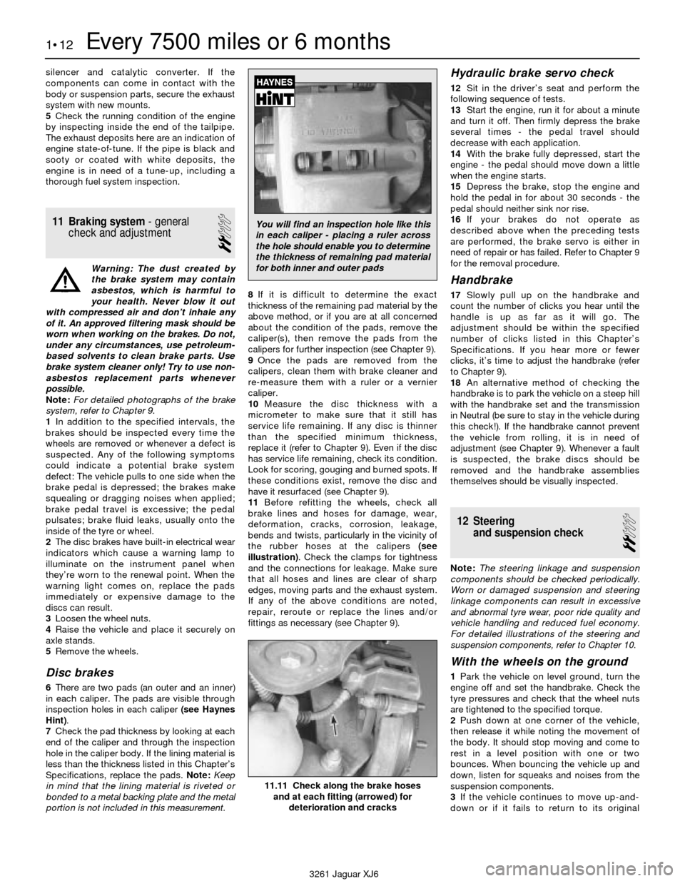
inspection holes in each caliper (see Haynes
Hint).
7Check the pad thickness by looking at each
end of the caliper and through the inspection
hole in the caliper body. If the lining material is
less than the thickness listed in this Chapter’s
Specifications, replace the pads. Note:Keep
in mind that the lining material is riveted or
bonded to a metal backing plate and the metal
portion is not included in this measurement.8If it is difficult to determine the exact
thickness of the remaining pad material by the
above method, or if you are at all concerned
about the condition of the pads, remove the
caliper(s), then remove the pads from the
calipers for further inspection (see Chapter 9).
9Once the pads are removed from the
calipers, clean them with brake cleaner and
re-measure them with a ruler or a vernier
caliper.
10Measure the disc thickness with a
micrometer to make sure that it still has
service life remaining. If any disc is thinner
than the specified minimum thickness,
replace it (refer to Chapter 9). Even if the disc
has service life remaining, check its condition.
Look for scoring, gouging and burned spots. If
these conditions exist, remove the disc and
have it resurfaced (see Chapter 9).
11Before refitting the wheels, check all
brake lines and hoses for damage, wear,
deformation, cracks, corrosion, leakage,
bends and twists, particularly in the vicinity of
the rubber hoses at the calipers (see
illustration). Check the clamps for tightness
and the connections for leakage. Make sure
that all hoses and lines are clear of sharp
edges, moving parts and the exhaust system.
If any of the above conditions are noted,
repair, reroute or replace the lines and/or
fittings as necessary (see Chapter 9).
Hydraulic brake servo check
12Sit in the driver’s seat and perform the
following sequence of tests.
13Start the engine, run it for about a minute
and turn it off. Then firmly depress the brake
several times - the pedal travel should
decrease with each application.
14With the brake fully depressed, start the
engine - the pedal should move down a little
when the engine starts.
15Depress the brake, stop the engine and
hold the pedal in for about 30 seconds - the
pedal should neither sink nor rise.
16If your brakes do not operate as
described above when the preceding tests
are performed, the brake servo is either in
need of repair or has failed. Refer to Chapter 9
for the removal procedure.
Handbrake
17Slowly pull up on the handbrake and
count the number of clicks you hear until the
handle is up as far as it will go. The
adjustment should be within the specified
number of clicks listed in this Chapter’s
Specifications. If you hear more or fewer
clicks, it’s time to adjust the handbrake (refer
to Chapter 9).
18An alternative method of checking the
handbrake is to park the vehicle on a steep hill
with the handbrake set and the transmission
in Neutral (be sure to stay in the vehicle during
this check!). If the handbrake cannot prevent
the vehicle from rolling, it is in need of
adjustment (see Chapter 9). Whenever a fault
is suspected, the brake discs should be
removed and the handbrake assemblies
themselves should be visually inspected.
12 Steering
and suspension check
2
Note: The steering linkage and suspension
components should be checked periodically.
Worn or damaged suspension and steering
linkage components can result in excessive
and abnormal tyre wear, poor ride quality and
vehicle handling and reduced fuel economy.
For detailed illustrations of the steering and
suspension components, refer to Chapter 10.
With the wheels on the ground
1Park the vehicle on level ground, turn the
engine off and set the handbrake. Check the
tyre pressures and check that the wheel nuts
are tightened to the specified torque.
2Push down at one corner of the vehicle,
then release it while noting the movement of
the body. It should stop moving and come to
rest in a level position with one or two
bounces. When bouncing the vehicle up and
down, listen for squeaks and noises from the
suspension components.
3If the vehicle continues to move up-and-
down or if it fails to return to its original
1•12Every 7500 miles or 6 months
11.11 Check along the brake hoses
and at each fitting (arrowed) for
deterioration and cracks
3261 Jaguar XJ6
You will find an inspection hole like this
in each caliper - placing a ruler across
the hole should enable you to determine
the thickness of remaining pad material
for both inner and outer pads
Page 61 of 227
incorporated throughout. The refitting of
manifolds and external parts is all that’s
necessary. Engines in this rebuilt form are
available from Jaguar dealers, and some
independent rebuilders.
Give careful thought to which alternative is
best for you and discuss the situation with
local automotive machine shops, auto parts
dealers and experienced rebuilders before
ordering or purchasing replacement parts.
8 Engine overhaul-
dismantling sequence
1It’s much easier to dismantle and work on
the engine if it’s mounted on a portable
engine stand. A stand can often be rented
quite cheaply from an equipment rental yard.
Before the engine is mounted on a stand, the
driveplate and rear oil seal retainer should be
removed from the engine.
2If a stand isn’t available, it’s possible to
dismantle the engine with it blocked up on the
floor. Be extra careful not to tip or drop the
engine when working without a stand.
3If you’re going to obtain a rebuilt engine, all
external components must come off first, to
be transferred to the replacement engine, just
as they will if you’re doing a complete engine
overhaul yourself. These include:
Alternator and brackets
Emissions control components
Distributor, spark plug leads and spark
plugs
Thermostat and housing cover
Water pump
EFI components
Intake/exhaust manifolds
Oil filter
Engine mounts
Driveplate
Transmission adapter plate
Note:When removing the external
components from the engine, pay close
attention to details that may be helpful or
important during refitting. Note the installed
position of gaskets, seals, spacers, pins,
brackets, washers, bolts and other small items.
4If you’re obtaining a short block, which
consists of the engine block, crankshaft,
pistons and connecting rods all assembled,
then the cylinder head, sump and oil pump will
have to be removed as well from your engine
so that your short-block can be turned in to
the rebuilder as a core. See Engine rebuilding
alternativesfor additional information
regarding the different possibilities to be
considered.
5If you’re planning a complete overhaul, the
engine must be dismantled and the internal
components removed in the following order:
Intake and exhaust manifolds
Valve cover
Upper timing chain and camshaft
sprocketsCamshafts
Timing chain cover
Cylinder head
Sump
Oil pump
Piston/connecting rod assemblies
Crankshaft rear oil seal retainer
Crankshaft and main bearings
6Before beginning the dismantling and
overhaul procedures, make sure the following
items are available. Also, refer to Section 21
for a list of tools and materials needed for
engine reassembly.
Common hand tools
Small cardboard boxes or plastic bags for
storing parts
Gasket scraper
Ridge reamer
Micrometers
Telescoping gauges
Dial indicator set
Valve spring compressor
Cylinder surfacing hone
Piston ring groove-cleaning tool
Electric drill motor
Tap and die set
Wire brushes
Oil gallery brushes
Cleaning solvent
Special Jaguar tools
Engine lifting brackets (18G 1465)
Timing damper simulator (18E 1436)
Camshaft TDC tool (18G 1433)
9 Cylinder head- dismantling
2
Note: New and rebuilt cylinder heads are
available from Jaguar and some independent
rebuilders. Due to the fact that some
specialised tools are necessary for the
dismantling and inspection procedures, and
replacement parts may not be readily
available, it may be more practical and
economical for the home mechanic to
purchase a replacement cylinder head rather
than taking the time to dismantle, inspect and
recondition the original.1Cylinder head dismantling involves removal
of the intake and exhaust valves and related
components. It’s assumed that the lifters and
camshafts have already been removed (see
Part A as needed).
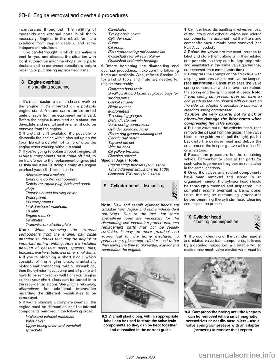
2Before the valves are removed, arrange to
label and store them, along with their related
components, so they can be kept separate
and reinstalled in the same valve guides they
are removed from (see illustration).
3Compress the springs on the first valve with
a spring compressor and remove the keepers
(see illustration). Carefully release the valve
spring compressor and remove the retainer,
the spring and the spring seat (if used). Note:
If your spring compressor does not have an
end (such as the one shown) with cut-outs on
the side, an adapter is available to use with a
standard spring compressor.
Caution: Be very careful not to nick or
otherwise damage the lifter bores when
compressing the valve springs.
4Pull the valve out of the cylinder head, then
remove the oil seal from the guide. If the valve
binds in the guide (won’t pull through), push it
back into the cylinder head and deburr the
area around the keeper groove with a fine file
or whetstone.
5Repeat the procedure for the remaining
valves. Remember to keep all the parts for
each valve together so they can be reinstalled
in the same locations.
6Once the valves and related components
have been removed and stored in an
organised manner, the cylinder head should
be thoroughly cleaned and inspected. If a
complete engine overhaul is being done,
finish the engine dismantling procedures
before beginning the cylinder head cleaning
and inspection process.
10 Cylinder head-
cleaning and inspection
2
1Thorough cleaning of the cylinder head(s)
and related valve train components, followed
by a detailed inspection, will enable you to
decide how much valve service work must be
2B•6 Engine removal and overhaul procedures
9.2 A small plastic bag, with an appropriate
label, can be used to store the valve train
components so they can be kept together
and reinstalled in the correct guide
3261 Jaguar XJ6
9.3 Compress the spring until the keepers
can be removed with a small magnetic
screwdriver or needle-nose pliers - use a
valve spring compressor with an adapter
(arrowed) to remove the keepers
Page 63 of 227
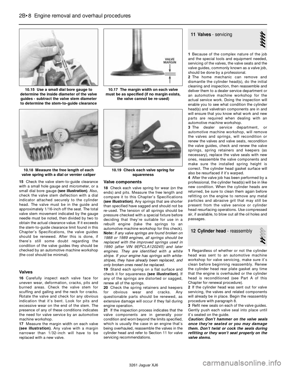
15Check the valve stem-to-guide clearance
with a small hole gauge and micrometer, or a
small dial bore gauge (see illustration). Also,
check the valve stem deflection with a dial
indicator attached securely to the cylinder
head. The valve must be in the guide and
approximately 1/16-inch off the seat. The total
valve stem movement indicated by the gauge
needle must be noted, then divided by two to
obtain the actual clearance value. If it exceeds
the stem-to-guide clearance limit found in this
Chapter’s Specifications, the valve guides
should be renewed. After this is done, if
there’s still some doubt regarding the
condition of the valve guides they should be
checked by an automotive machine workshop
(the cost should be minimal).
Valves
16Carefully inspect each valve face for
uneven wear, deformation, cracks, pits and
burned areas. Check the valve stem for
scuffing and galling and the neck for cracks.
Rotate the valve and check for any obvious
indication that it’s bent. Look for pits and
excessive wear on the end of the stem. The
presence of any of these conditions indicates
the need for valve service by an automotive
machine workshop.
17Measure the margin width on each valve
(see illustration). Any valve with a margin
narrower than 1/32-inch will have to be
replaced with a new valve.
Valve components
18Check each valve spring for wear (on the
ends) and pits. Measure the free length and
compare it to this Chapter’s Specifications
(see illustration). Any springs that are shorter
than specified have sagged and should not be
re-used. The tension of all springs should be
pressure checked with a special fixture before
deciding that they’re suitable for use in a
rebuilt engine (take the springs to an
automotive machine workshop for this check).
Note:If any valve springs are found broken on
1988 or 1989 engines, all springs should be
replaced with the improved springs used in
1990 (after VIN 9EPCLA120245) and later
engines. They are identified with a white
stripe. If your engine has springs with white-
stripes, they have already been replaced, and
only broken ones need be replaced.
19Stand each spring on a flat surface and
check it for squareness (see illustration). If
any of the springs are distorted or sagged,
renew all of the springs.
20Check the spring retainers and keepers
for obvious wear and cracks. Any
questionable parts should be renewed, as
extensive damage will occur if they fail during
engine operation.
21If the inspection process indicates that the
valve components are in generally poor
condition and worn beyond the limits specified,
which is usually the case in an engine that’s
being overhauled, reassemble the valves in the
cylinder head and refer to Section 11 for valve
servicing recommendations.
11 Valves- servicing
5
1Because of the complex nature of the job
and the special tools and equipment needed,
servicing of the valves, the valve seats and the
valve guides, commonly known as a valve job,
should be done by a professional.
2The home mechanic can remove and
dismantle the cylinder head(s), do the initial
cleaning and inspection, then reassemble and
deliver them to a dealer service department or
an automotive machine workshop for the
actual service work. Doing the inspection will
enable you to see what condition the cylinder
head(s) and valvetrain components are in and
will ensure that you know what work and new
parts are required when dealing with an
automotive machine workshop.
3The dealer service department, or
automotive machine workshop, will remove
the valves and springs, will recondition or
renew the valves and valve seats, recondition
the valve guides, check and renew the valve
springs, spring retainers and keepers (as
necessary), replace the valve seals with new
ones, reassemble the valve components and
make sure the installed spring height is
correct. The cylinder head gasket surface will
also be resurfaced if it’s warped.
4After the valve job has been performed by a
professional, the cylinder head(s) will be in like
new condition. When the cylinder heads are
returned, be sure to clean them again before
refitting on the engine to remove any metal
particles and abrasive grit that may still be
present from the valve service or cylinder
head resurfacing operations. Use compressed
air, if available, to blow out all the oil holes and
passages.
12 Cylinder head- reassembly
2
1Regardless of whether or not the cylinder
head was sent to an automotive machine
workshop for valve servicing, make sure it’s
clean before beginning reassembly. Renew
the cylinder head rear plate gasket any time
that the engine is overhauled or the cylinder
head is reconditioned (see Part A of this
Chapter for renewal procedure).
2If the cylinder head was sent out for valve
servicing, the valves and related components
will already be in place. Begin the reassembly
procedure with paragraph 8.
3Refit new seals on each of the valve guides.
Gently push each valve seal into place until
it’s seated on the guide.
Caution: Don’t hammer on the valve seals
once they’re seated or you may damage
them. Don’t twist or cock the seals during
refitting or they won’t seat properly on the
valve stems.
2B•8 Engine removal and overhaul procedures
10.15 Use a small dial bore gauge to
determine the inside diameter of the valve
guides - subtract the valve stem diameter
to determine the stem-to-guide clearance10.17 The margin width on each valve
must be as specified (if no margin exists,
the valve cannot be re-used)
10.18 Measure the free length of each
valve spring with a dial or vernier caliper10.19 Check each valve spring for
squareness
3261 Jaguar XJ6
Page 107 of 227
Refitting
7Insert the distributor into the engine in
exactly the same relationship to the block that
it was in when removed.
8If the distributor does not seat completely,
recheck the alignment marks between the
distributor base and the block to verify that
the distributor is in the same position it was in
before removal. Also check the rotor to see if
it’s aligned with the mark you made on the
edge of the distributor base.
9Refit the distributor hold-down bolt(s).
10The remainder of refitting is the reverse of
removal.
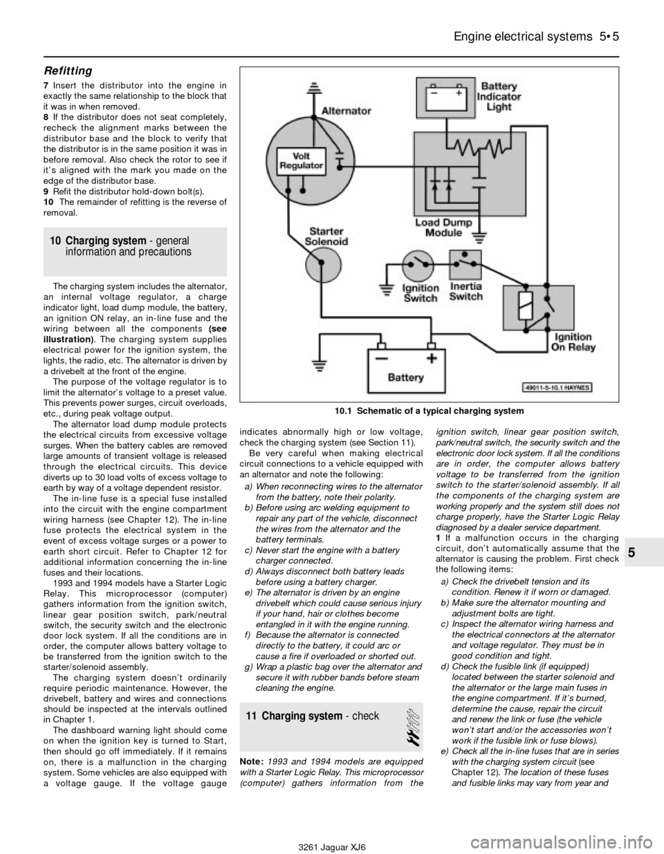
10 Charging system- general
information and precautions
The charging system includes the alternator,
an internal voltage regulator, a charge
indicator light, load dump module, the battery,
an ignition ON relay, an in-line fuse and the
wiring between all the components (see
illustration). The charging system supplies
electrical power for the ignition system, the
lights, the radio, etc. The alternator is driven by
a drivebelt at the front of the engine.
The purpose of the voltage regulator is to
limit the alternator’s voltage to a preset value.
This prevents power surges, circuit overloads,
etc., during peak voltage output.
The alternator load dump module protects
the electrical circuits from excessive voltage
surges. When the battery cables are removed
large amounts of transient voltage is released
through the electrical circuits. This device
diverts up to 30 load volts of excess voltage to
earth by way of a voltage dependent resistor.
The in-line fuse is a special fuse installed
into the circuit with the engine compartment
wiring harness (see Chapter 12). The in-line
fuse protects the electrical system in the
event of excess voltage surges or a power to
earth short circuit. Refer to Chapter 12 for
additional information concerning the in-line
fuses and their locations.
1993 and 1994 models have a Starter Logic
Relay. This microprocessor (computer)
gathers information from the ignition switch,
linear gear position switch, park/neutral
switch, the security switch and the electronic
door lock system. If all the conditions are in
order, the computer allows battery voltage to
be transferred from the ignition switch to the
starter/solenoid assembly.
The charging system doesn’t ordinarily
require periodic maintenance. However, the
drivebelt, battery and wires and connections
should be inspected at the intervals outlined
in Chapter 1.
The dashboard warning light should come
on when the ignition key is turned to Start,
then should go off immediately. If it remains
on, there is a malfunction in the charging
system. Some vehicles are also equipped with
a voltage gauge. If the voltage gaugeindicates abnormally high or low voltage,
check the charging system (see Section 11).
Be very careful when making electrical
circuit connections to a vehicle equipped with
an alternator and note the following:
a) When reconnecting wires to the alternator
from the battery, note their polarity.
b) Before using arc welding equipment to
repair any part of the vehicle, disconnect
the wires from the alternator and the
battery terminals.
c) Never start the engine with a battery
charger connected.
d) Always disconnect both battery leads
before using a battery charger.
e) The alternator is driven by an engine
drivebelt which could cause serious injury
if your hand, hair or clothes become
entangled in it with the engine running.
f) Because the alternator is connected
directly to the battery, it could arc or
cause a fire if overloaded or shorted out.
g) Wrap a plastic bag over the alternator and
secure it with rubber bands before steam
cleaning the engine.
11 Charging system- check
2
Note:1993 and 1994 models are equipped
with a Starter Logic Relay. This microprocessor
(computer) gathers information from theignition switch, linear gear position switch,
park/neutral switch, the security switch and the
electronic door lock system. If all the conditions
are in order, the computer allows battery
voltage to be transferred from the ignition
switch to the starter/solenoid assembly. If all
the components of the charging system are
working properly and the system still does not
charge properly, have the Starter Logic Relay
diagnosed by a dealer service department.
1If a malfunction occurs in the charging
circuit, don’t automatically assume that the
alternator is causing the problem. First check
the following items:
a) Check the drivebelt tension and its
condition. Renew it if worn or damaged.
b) Make sure the alternator mounting and
adjustment bolts are tight.
c) Inspect the alternator wiring harness and
the electrical connectors at the alternator
and voltage regulator. They must be in
good condition and tight.
d) Check the fusible link (if equipped)
located between the starter solenoid and
the alternator or the large main fuses in
the engine compartment. If it’s burned,
determine the cause, repair the circuit
and renew the link or fuse (the vehicle
won’t start and/or the accessories won’t
work if the fusible link or fuse blows).
e) Check all the in-line fuses that are in series
with the charging system circuit (see
Chapter 12).The location of these fuses
and fusible links may vary from year and
Engine electrical systems 5•5
5
10.1 Schematic of a typical charging system
3261 Jaguar XJ6
Page 108 of 227
model but the designations are the same.
Refer to the wiring diagrams at the end of
Chapter 12.
f) Start the engine and check the alternator
for abnormal noises (a shrieking or
squealing sound indicates a bad bushing).
g) Check the specific gravity of the battery
electrolyte. If it’s low, charge the battery
(doesn’t apply to maintenance free
batteries).
h) Make sure that the battery is fully charged
(one bad cell in a battery can cause
overcharging by the alternator).
i) Disconnect the battery cables (negative
first, then positive). Caution:If the stereo
in your vehicle is equipped with an anti-
theft system, make sure you have the
correct activation code before
disconnecting the battery. Inspect the
battery posts and the cable clamps for
corrosion. Clean them thoroughly if
necessary (see Chapter 1). Reconnect the
positive cable, then the negative cable.
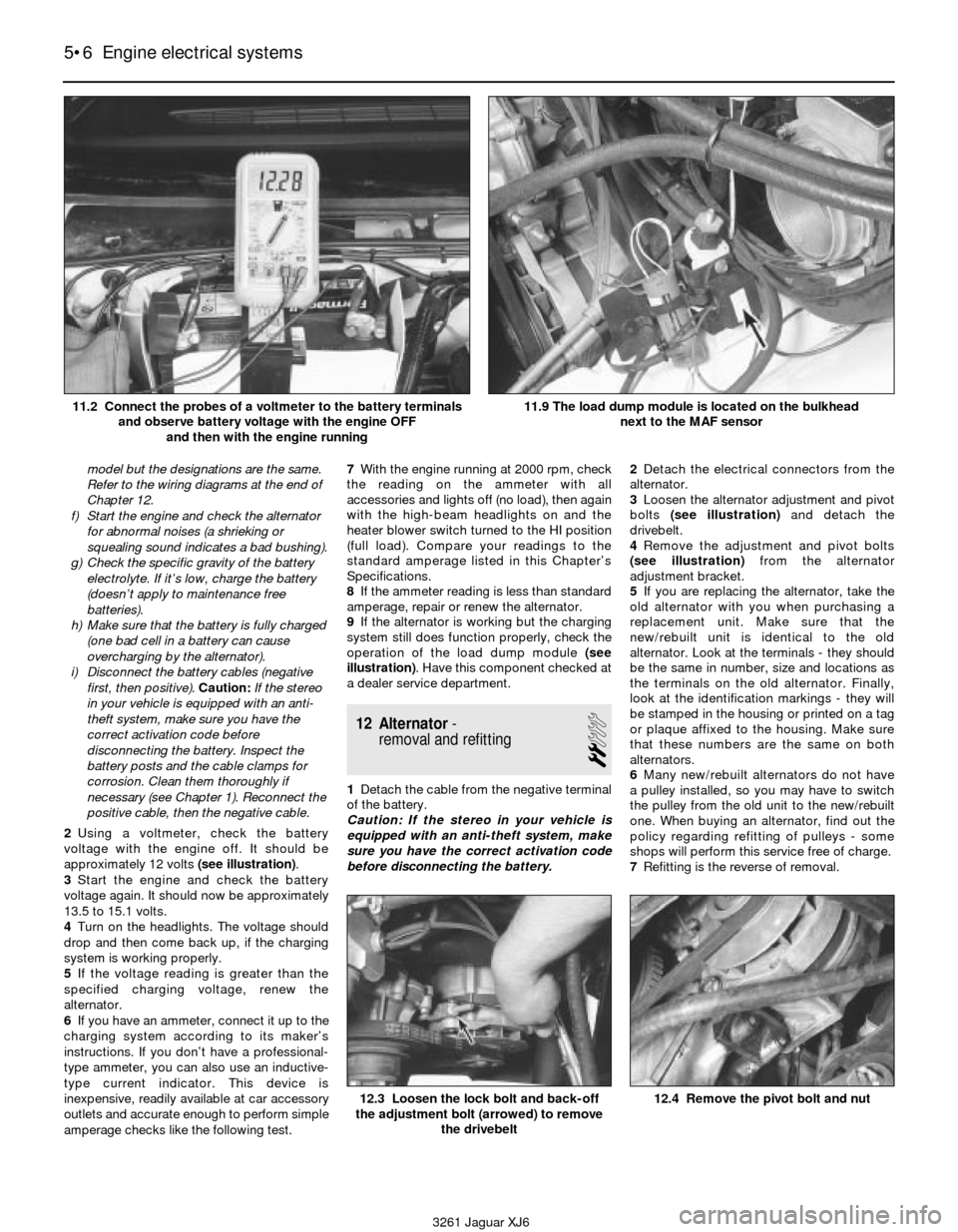
2Using a voltmeter, check the battery
voltage with the engine off. It should be
approximately 12 volts (see illustration).
3Start the engine and check the battery
voltage again. It should now be approximately
13.5 to 15.1 volts.
4Turn on the headlights. The voltage should
drop and then come back up, if the charging
system is working properly.
5If the voltage reading is greater than the
specified charging voltage, renew the
alternator.
6If you have an ammeter, connect it up to the
charging system according to its maker’s
instructions. If you don’t have a professional-
type ammeter, you can also use an inductive-
type current indicator. This device is
inexpensive, readily available at car accessory
outlets and accurate enough to perform simple
amperage checks like the following test.7With the engine running at 2000 rpm, check
the reading on the ammeter with all
accessories and lights off (no load), then again
with the high-beam headlights on and the
heater blower switch turned to the HI position
(full load). Compare your readings to the
standard amperage listed in this Chapter’s
Specifications.
8If the ammeter reading is less than standard
amperage, repair or renew the alternator.
9If the alternator is working but the charging
system still does function properly, check the
operation of the load dump module (see
illustration). Have this component checked at
a dealer service department.
12 Alternator-
removal and refitting
2
1Detach the cable from the negative terminal
of the battery.
Caution: If the stereo in your vehicle is
equipped with an anti-theft system, make
sure you have the correct activation code
before disconnecting the battery.2Detach the electrical connectors from the
alternator.
3Loosen the alternator adjustment and pivot
bolts (see illustration) and detach the
drivebelt.
4Remove the adjustment and pivot bolts
(see illustration)from the alternator
adjustment bracket.
5If you are replacing the alternator, take the
old alternator with you when purchasing a
replacement unit. Make sure that the
new/rebuilt unit is identical to the old
alternator. Look at the terminals - they should
be the same in number, size and locations as
the terminals on the old alternator. Finally,
look at the identification markings - they will
be stamped in the housing or printed on a tag
or plaque affixed to the housing. Make sure
that these numbers are the same on both
alternators.
6Many new/rebuilt alternators do not have
a pulley installed, so you may have to switch
the pulley from the old unit to the new/rebuilt
one. When buying an alternator, find out the
policy regarding refitting of pulleys - some
shops will perform this service free of charge.
7Refitting is the reverse of removal.
5•6 Engine electrical systems
12.3 Loosen the lock bolt and back-off
the adjustment bolt (arrowed) to remove
the drivebelt12.4 Remove the pivot bolt and nut
3261 Jaguar XJ6 11.2 Connect the probes of a voltmeter to the battery terminals
and observe battery voltage with the engine OFF
and then with the engine running
11.9 The load dump module is located on the bulkhead
next to the MAF sensor
Page 163 of 227
3261 Jaguar XJ6
12
Chapter 12
Body electrical system
1 General information
The electrical system is a 12-volt, negative
earth type. Power for the lights and all
electrical accessories is supplied by a
lead/acid-type battery which is charged by
the alternator.
This Chapter covers repair and service
procedures for the various electrical
components not associated with the engine.
Information on the battery, alternator,
distributor and starter motor will be found in
Chapter 5.
It should be noted that when portions of the
electrical system are serviced, the cable
should be disconnected from the negative
battery terminal to prevent electrical shorts
and/or fires.
2 Electrical fault finding-
general information
A typical electrical circuit consists of an
electrical component, any switches, relays,
motors, fuses, fusible links, in-line fuses or
circuit breakers related to that component
and the wiring and electrical connectors that
link the component to both the battery andthe chassis. To help you pinpoint an electrical
circuit problem, wiring diagrams are included
at the end of this Chapter.
Before tackling any troublesome electrical
circuit, first study the appropriate wiring
diagrams to get a complete understanding of
what makes up that individual circuit. Trouble
spots, for instance, can often be narrowed
down by noting if other components related to
the circuit are operating properly. If several
components or circuits fail at one time,
chances are the problem is in a fuse or earth
connection, because several circuits are often
routed through the same fuse and earth
connections.
Electrical problems usually stem from
simple causes, such as loose or corroded
connections, a blown fuse, a melted fusible
link or a bad relay. Visually inspect the
condition of all fuses, wires and connections
in a problem circuit before diagnosing it.
If testing instruments are going to be
utilised, use the diagrams to plan ahead of
time where you will make the necessary
connections in order to accurately pinpoint
the trouble spot.
The basic tools needed for electrical fault
finding include a circuit tester or voltmeter (a
12-volt bulb with a set of test leads can also
be used), a continuity tester, which includes a
bulb, battery and set of test leads, and a
jumper wire, preferably with a circuit breaker
incorporated, which can be used to bypasselectrical components. Before attempting to
locate a problem with test instruments,
use the wiring diagram(s) to decide where to
make the connections.
Voltage checks
Voltage checks should be performed if a
circuit is not functioning properly. Connect
one lead of a circuit tester to either the
negative battery terminal or a known good
earth. Connect the other lead to a electrical
connector in the circuit being tested,
preferably nearest to the battery or fuse. If the
bulb of the tester lights, voltage is present,
which means that the part of the circuit
between the electrical connector and the
battery is problem free. Continue checking the
rest of the circuit in the same fashion. When
you reach a point at which no voltage is
present, the problem lies between that point
and the last test point with voltage. Most of
the time the problem can be traced to a loose
connection. Note:Keep in mind that some
circuits receive voltage only when the ignition
key is in the Accessory or Run position.
Finding a short
One method of finding shorts in a circuit is
to remove the fuse and connect a test light or
voltmeter in its place. There should be no
voltage present in the circuit. Move the wiring
harness from side to side while watching the
test light. If the bulb goes on, there is a short Airbag system - general information . . . . . . . . . . . . . . . . . . . . . . . . . 28
Bulb renewal . . . . . . . . . . . . . . . . . . . . . . . . . . . . . . . . . . . . . . . . . . . 21
Central locking system - description and check . . . . . . . . . . . . . . . . 25
Circuit breakers - general information . . . . . . . . . . . . . . . . . . . . . . . . 5
Cruise control system - description and check . . . . . . . . . . . . . . . . . 23
Direction indicators/hazard flashers - general information . . . . . . . . 7
Electric aerial - removal and refitting . . . . . . . . . . . . . . . . . . . . . . . . . 14
Electric side view mirrors - description and check . . . . . . . . . . . . . . 26
Electric sunroof - description and check . . . . . . . . . . . . . . . . . . . . . . 27
Electric window system - description and check . . . . . . . . . . . . . . . 24
Electrical fault finding - general information . . . . . . . . . . . . . . . . . . . 2
Fuel, oil and temperature gauges - check . . . . . . . . . . . . . . . . . . . . . 11
Fuses - general information . . . . . . . . . . . . . . . . . . . . . . . . . . . . . . . . 3
General information . . . . . . . . . . . . . . . . . . . . . . . . . . . . . . . . . . . . . . 1
Headlight housing (1992 to 1994 models) - removal and refitting . . . 19Headlights - adjustment . . . . . . . . . . . . . . . . . . . . . . . . . . . . . . . . . . 18
Headlights - renewal . . . . . . . . . . . . . . . . . . . . . . . . . . . . . . . . . . . . . 17
Heated rear window - check and repair . . . . . . . . . . . . . . . . . . . . . . 16
Horn - check and renewal . . . . . . . . . . . . . . . . . . . . . . . . . . . . . . . . . 20
Ignition switch and key lock cylinder - removal and refitting . . . . . . 9
Inertia switch - description and check . . . . . . . . . . . . . . . . . . . . . . . . 22
In-line fuses - general information . . . . . . . . . . . . . . . . . . . . . . . . . . . 4
Instrument cluster - removal and refitting . . . . . . . . . . . . . . . . . . . . . 12
Instrument panel switches - removal and refitting . . . . . . . . . . . . . . 10
Radio and speakers - removal and refitting . . . . . . . . . . . . . . . . . . . 13
Relays - general information and testing . . . . . . . . . . . . . . . . . . . . . . 6
Steering column switches - removal and refitting . . . . . . . . . . . . . . . 8
Windscreen wiper motor - removal and refitting . . . . . . . . . . . . . . . . 15
Wiring diagrams - general information . . . . . . . . . . . . . . . . . . . . . . . 29
12•1
Contents
Easy,suitable for
novice with little
experienceFairly easy,suitable
for beginner with
some experienceFairly difficult,
suitable for competent
DIY mechanic
Difficult,suitable for
experienced DIY
mechanicVery difficult,
suitable for expert DIY
or professional
Degrees of difficulty
54321
Page 166 of 227

can be removed and tested using the
procedure below or by a dealer service
department or a repair workshop. Defective
relays must be replaced as a unit.
Testing
1It’s best to refer to the wiring diagram for
the circuit to determine the proper
connections for the relay you’re testing.
However, if you’re not able to determine the
correct connection from the wiring diagrams,
you may be able to determine the test
connections from the information that follows.
2On most relays, two of the terminals are the
relay’s control circuit (they connect to the
relay coil which, when energised, closes the
large contacts to complete the circuit). The
other terminals are the power circuit (they are
connected together within the relay when the
control-circuit coil is energised).
3Relays are sometimes marked as an aid to
help you determine which terminals are the
control circuit and which are the powercircuit (see illustration). As a general rule,
the two thicker wires connected to the relay
are the power circuit; the thinner wires are
the control circuit.
4Remove the relay from the vehicle and check
for continuity between the relay power circuit
terminals. There should be no continuity.5Connect a fused jumper wire between one
of the two control circuit terminals and the
positive battery terminal. Connect another
jumper wire between the other control circuit
terminal and earth. When the connections are
made, the relay should click. On some relays,
polarity may be critical, so, if the relay doesn’t
click, try swapping the jumper wires on the
control circuit terminals.
6With the jumper wires connected, check for
continuity between the power circuit
terminals. Now, there should be continuity.
8If the relay fails any of the above tests,
renew it.
7 Direction indicator/hazard
flasher- general information
Warning: Later model vehicles
are equipped with airbags. To
prevent accidental deployment6.3 Most relays are marked on the outside
to easily identify the control circuit and
power circuits
12•4 Body electrical system
3261 Jaguar XJ6 1990 to 1992 relay location details
Page 167 of 227

of the airbag, which could cause personal
injury or damage to the airbag system, DO
NOT work in the vicinity of the steering
column or instrument panel. The
manufacturer recommends that, on airbag
equipped models, the following procedure
be performed at a dealer service
department or other properly equipped
repair facility because of the special tools
and techniques required to disable the
airbag system.
The direction indicator and hazard flasher
systems are governed by the central
processing unit. The central processing unit
requires special testers and diagnostic
procedures which are beyond the scope of
this manual.
If the direction indicator/hazard flasher
system fails and the indicator bulbs are in
working condition take the vehicle to a dealer
service department or an automotive
electrical specialist for further diagnosis and
repair.8 Steering column switches-
removal and refitting
1
Warning: Later models are
equipped with airbags. To
prevent accidental deployment
of the airbag, which could cause
personal injury or damage to the airbag
system, DO NOT work in the vicinity of the
steering column or instrument panel. The
manufacturer recommends that, on airbag
equipped models, the following procedure
be performed at a dealer service
department or other properly equipped
repair facility because of the special tools
and techniques required to disable the
airbag system.
Caution: If the stereo in your vehicle is
equipped with an anti-theft system, make
sure you have the correct activation code
before disconnecting the battery.1Disconnect the negative battery cable.
2Remove the steering wheel (Chapter 10).
3Remove the lower steering column cover
(see Chapter 11).
4Remove the switch retaining screw(s) (see
illustration).
Body electrical system 12•5
12
3261 Jaguar XJ6 1993 to 1994 relay location details
8.4 Remove the switch retaining screws,
disconnect the electrical connectors and
pull the switches outward (arrowed)