reset JAGUAR XJ6 1997 2.G Workshop Manual
[x] Cancel search | Manufacturer: JAGUAR, Model Year: 1997, Model line: XJ6, Model: JAGUAR XJ6 1997 2.GPages: 227, PDF Size: 7.2 MB
Page 91 of 227
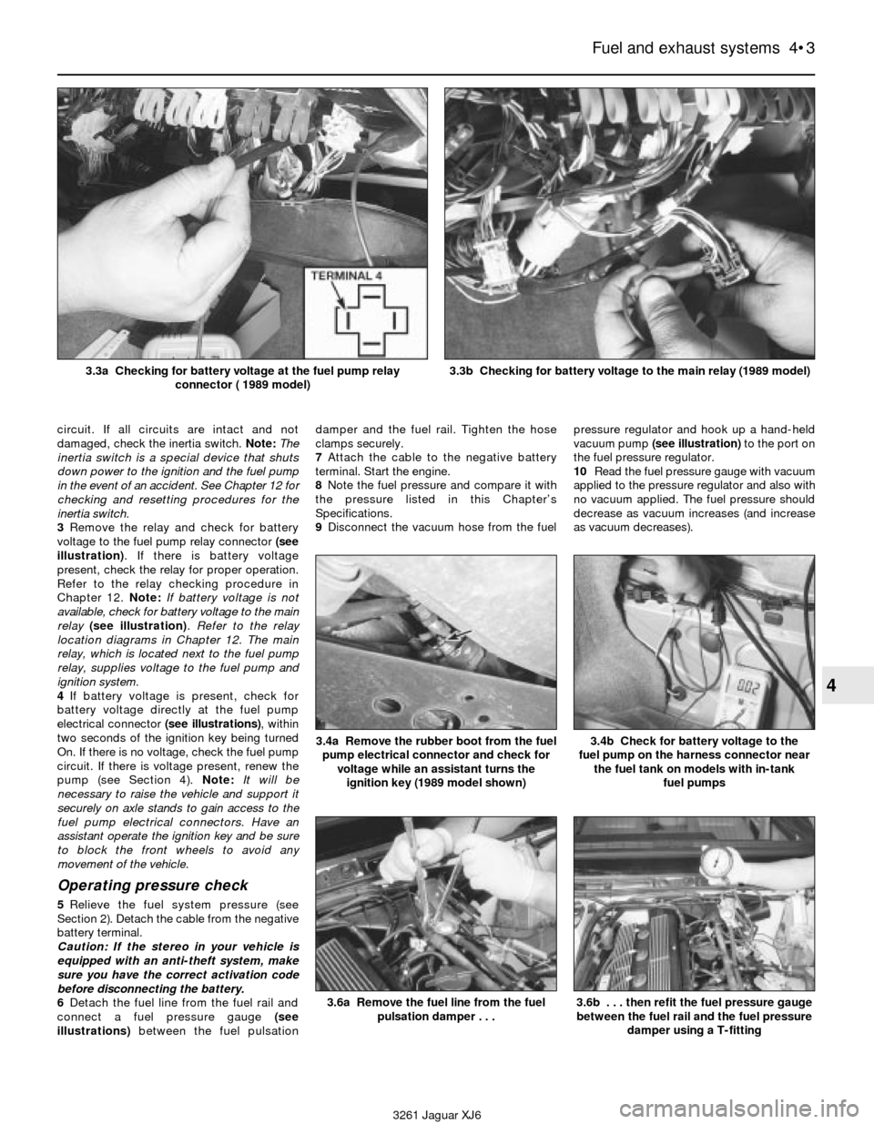
circuit. If all circuits are intact and not
damaged, check the inertia switch. Note: The
inertia switch is a special device that shuts
down power to the ignition and the fuel pump
in the event of an accident. See Chapter 12 for
checking and resetting procedures for the
inertia switch.
3Remove the relay and check for battery
voltage to the fuel pump relay connector (see
illustration). If there is battery voltage
present, check the relay for proper operation.
Refer to the relay checking procedure in
Chapter 12. Note:If battery voltage is not
available, check for battery voltage to the main
relay(see illustration). Refer to the relay
location diagrams in Chapter 12. The main
relay, which is located next to the fuel pump
relay, supplies voltage to the fuel pump and
ignition system.
4If battery voltage is present, check for
battery voltage directly at the fuel pump
electrical connector (see illustrations), within
two seconds of the ignition key being turned
On. If there is no voltage, check the fuel pump
circuit. If there is voltage present, renew the
pump (see Section 4). Note:It will be
necessary to raise the vehicle and support it
securely on axle stands to gain access to the
fuel pump electrical connectors. Have an
assistant operate the ignition key and be sure
to block the front wheels to avoid any
movement of the vehicle.
Operating pressure check
5Relieve the fuel system pressure (see
Section 2). Detach the cable from the negative
battery terminal.
Caution: If the stereo in your vehicle is
equipped with an anti-theft system, make
sure you have the correct activation code
before disconnecting the battery.
6Detach the fuel line from the fuel rail and
connect a fuel pressure gauge(see
illustrations)between the fuel pulsationdamper and the fuel rail. Tighten the hose
clamps securely.
7Attach the cable to the negative battery
terminal. Start the engine.
8Note the fuel pressure and compare it with
the pressure listed in this Chapter’s
Specifications.
9Disconnect the vacuum hose from the fuelpressure regulator and hook up a hand-held
vacuum pump (see illustration)to the port on
the fuel pressure regulator.
10Read the fuel pressure gauge with vacuum
applied to the pressure regulator and also with
no vacuum applied. The fuel pressure should
decrease as vacuum increases (and increase
as vacuum decreases).
Fuel and exhaust systems 4•3
4
3261 Jaguar XJ6 3.3a Checking for battery voltage at the fuel pump relay
connector ( 1989 model)
3.3b Checking for battery voltage to the main relay (1989 model)
3.6a Remove the fuel line from the fuel
pulsation damper . . .
3.4b Check for battery voltage to the
fuel pump on the harness connector near
the fuel tank on models with in-tank
fuel pumps3.4a Remove the rubber boot from the fuel
pump electrical connector and check for
voltage while an assistant turns the
ignition key (1989 model shown)
3.6b . . . then refit the fuel pressure gauge
between the fuel rail and the fuel pressure
damper using a T-fitting
Page 107 of 227
Refitting
7Insert the distributor into the engine in
exactly the same relationship to the block that
it was in when removed.
8If the distributor does not seat completely,
recheck the alignment marks between the
distributor base and the block to verify that
the distributor is in the same position it was in
before removal. Also check the rotor to see if
it’s aligned with the mark you made on the
edge of the distributor base.
9Refit the distributor hold-down bolt(s).
10The remainder of refitting is the reverse of
removal.
10 Charging system- general
information and precautions
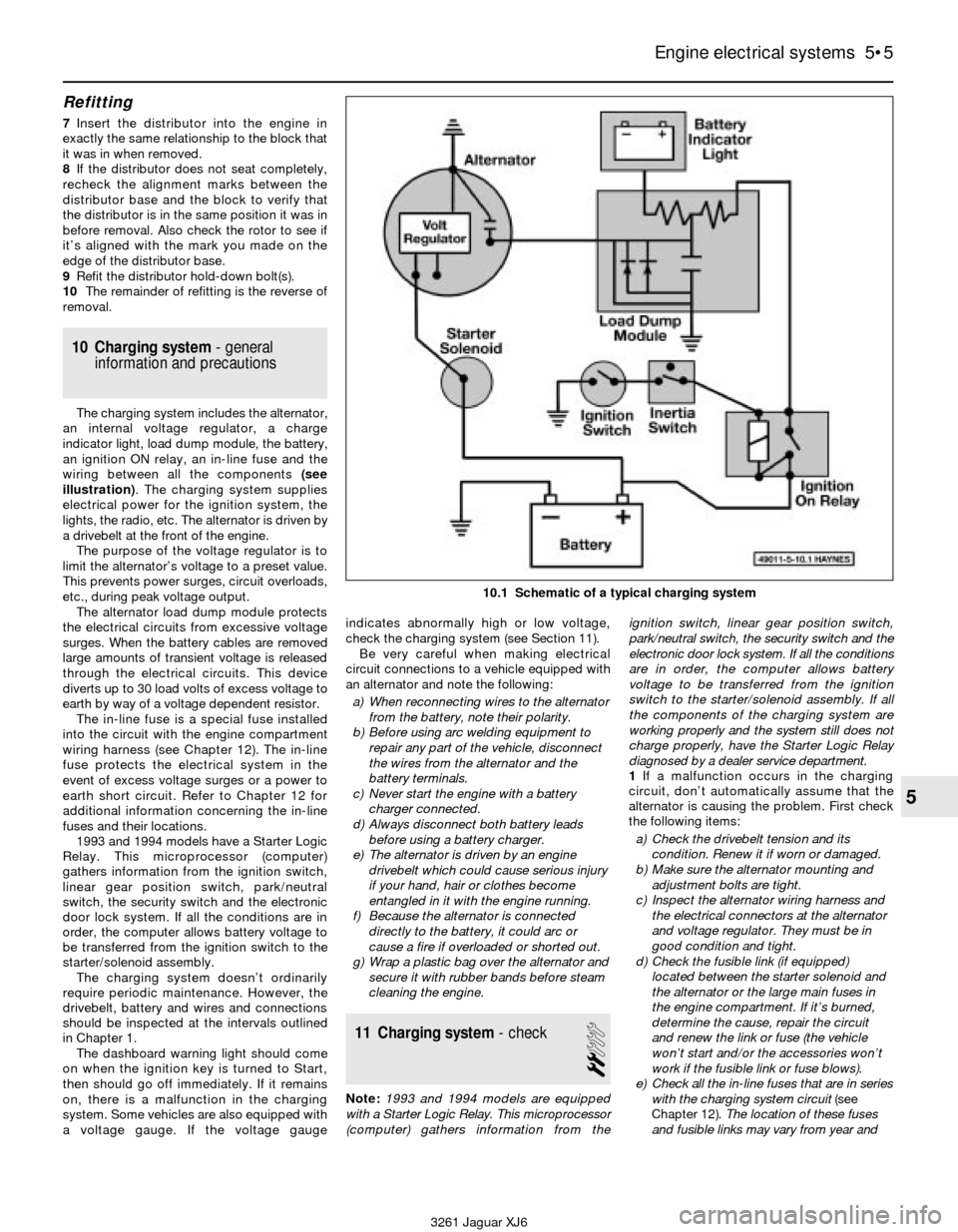
The charging system includes the alternator,
an internal voltage regulator, a charge
indicator light, load dump module, the battery,
an ignition ON relay, an in-line fuse and the
wiring between all the components (see
illustration). The charging system supplies
electrical power for the ignition system, the
lights, the radio, etc. The alternator is driven by
a drivebelt at the front of the engine.
The purpose of the voltage regulator is to
limit the alternator’s voltage to a preset value.
This prevents power surges, circuit overloads,
etc., during peak voltage output.
The alternator load dump module protects
the electrical circuits from excessive voltage
surges. When the battery cables are removed
large amounts of transient voltage is released
through the electrical circuits. This device
diverts up to 30 load volts of excess voltage to
earth by way of a voltage dependent resistor.
The in-line fuse is a special fuse installed
into the circuit with the engine compartment
wiring harness (see Chapter 12). The in-line
fuse protects the electrical system in the
event of excess voltage surges or a power to
earth short circuit. Refer to Chapter 12 for
additional information concerning the in-line
fuses and their locations.
1993 and 1994 models have a Starter Logic
Relay. This microprocessor (computer)
gathers information from the ignition switch,
linear gear position switch, park/neutral
switch, the security switch and the electronic
door lock system. If all the conditions are in
order, the computer allows battery voltage to
be transferred from the ignition switch to the
starter/solenoid assembly.
The charging system doesn’t ordinarily
require periodic maintenance. However, the
drivebelt, battery and wires and connections
should be inspected at the intervals outlined
in Chapter 1.
The dashboard warning light should come
on when the ignition key is turned to Start,
then should go off immediately. If it remains
on, there is a malfunction in the charging
system. Some vehicles are also equipped with
a voltage gauge. If the voltage gaugeindicates abnormally high or low voltage,
check the charging system (see Section 11).
Be very careful when making electrical
circuit connections to a vehicle equipped with
an alternator and note the following:
a) When reconnecting wires to the alternator
from the battery, note their polarity.
b) Before using arc welding equipment to
repair any part of the vehicle, disconnect
the wires from the alternator and the
battery terminals.
c) Never start the engine with a battery
charger connected.
d) Always disconnect both battery leads
before using a battery charger.
e) The alternator is driven by an engine
drivebelt which could cause serious injury
if your hand, hair or clothes become
entangled in it with the engine running.
f) Because the alternator is connected
directly to the battery, it could arc or
cause a fire if overloaded or shorted out.
g) Wrap a plastic bag over the alternator and
secure it with rubber bands before steam
cleaning the engine.
11 Charging system- check
2
Note:1993 and 1994 models are equipped
with a Starter Logic Relay. This microprocessor
(computer) gathers information from theignition switch, linear gear position switch,
park/neutral switch, the security switch and the
electronic door lock system. If all the conditions
are in order, the computer allows battery
voltage to be transferred from the ignition
switch to the starter/solenoid assembly. If all
the components of the charging system are
working properly and the system still does not
charge properly, have the Starter Logic Relay
diagnosed by a dealer service department.
1If a malfunction occurs in the charging
circuit, don’t automatically assume that the
alternator is causing the problem. First check
the following items:
a) Check the drivebelt tension and its
condition. Renew it if worn or damaged.
b) Make sure the alternator mounting and
adjustment bolts are tight.
c) Inspect the alternator wiring harness and
the electrical connectors at the alternator
and voltage regulator. They must be in
good condition and tight.
d) Check the fusible link (if equipped)
located between the starter solenoid and
the alternator or the large main fuses in
the engine compartment. If it’s burned,
determine the cause, repair the circuit
and renew the link or fuse (the vehicle
won’t start and/or the accessories won’t
work if the fusible link or fuse blows).
e) Check all the in-line fuses that are in series
with the charging system circuit (see
Chapter 12).The location of these fuses
and fusible links may vary from year and
Engine electrical systems 5•5
5
10.1 Schematic of a typical charging system
3261 Jaguar XJ6
Page 113 of 227
2The CHECK ENGINE warning light, which is
located on the instrument panel, comes on
when the ignition switch is turned to ON and
the engine is not running. When the engine is
started, the warning light should go out. If the
light remains on, the self-diagnosis system
has detected a malfunction. Note: The
CHECK ENGINE light on early models is
displayed on the dashboard VCM panel on the
right side. Later models are equipped with a
separate CHECK ENGINE light on the left side
of the instrument cluster.Note:Not all the
codes will cause the CHECK ENGINE light to
activate. When performing any fuel or
emissions systems diagnosis, always check
for codes that may be stored but not indicated
by the CHECK ENGINE light.
Obtaining fault code output
3To obtain an output of diagnostic codes,
verify first that the battery voltage is above 11
volts, the throttle is fully closed, the
transmission is in Park, the accessory
switches are off and the engine is at normal
operating temperature.
4Turn the ignition switch to ON but don’t
start the engine (Position II). Note:On 1988
and 1989 models, remember to turn the
ignition switch to position II without turning
the key to OFF.
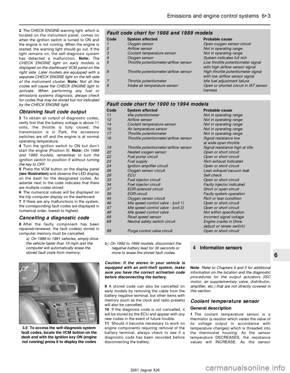
5Press the VCM button on the display panel
(see illustration)and observe the LED display
on the dash for the designated codes. An
asterisk next to the code indicates that there
are multiple codes stored.
6The numerical values will be displayed on
the trip computer display on the dashboard.
7If there are any malfunctions in the system,
the corresponding fault codes are displayed in
numerical order, lowest to highest.
Cancelling a diagnostic code
8After the faulty component has been
repaired/renewed, the fault code(s) stored in
computer memory must be cancelled.
a) On 1988 to 1991 vehicles, simply drive
the vehicle faster than 19 mph and the
computer will automatically erase the
stored fault code from memory.b) On 1992 to 1994 models, disconnect the
negative battery lead for 30 seconds or
more to erase the stored fault codes.
Caution: If the stereo in your vehicle is
equipped with an anti-theft system, make
sure you have the correct activation code
before disconnecting the battery.
9A stored code can also be cancelled on
early models by removing the cable from the
battery negative terminal, but other items with
memory (such as the clock and radio presets)
will also be cancelled.
10If the diagnosis code is not cancelled, it
will be stored by the ECU and appear with any
new codes in the event of future trouble.
11Should it become necessary to work on
engine components requiring removal of the
battery terminal, always check to see if a
diagnostic code has been recorded before
disconnecting the battery.
4 Information sensors
Note: Refer to Chapters 4 and 5 for additional
information on the location and the diagnostic
procedures for the output actuators (ISC
motor, air supplementary valve, distributor,
amplifier, etc.) that are not directly covered in
this section.
Coolant temperature sensor
General description
1The coolant temperature sensor is a
thermistor (a resistor which varies the value of
its voltage output in accordance with
temperature changes) which is threaded into
the thermostat housing. As the sensor
temperature DECREASES, the resistance
values will INCREASE. As the sensor
Emissions and engine control systems 6•3
6
3.5 To access the self-diagnosis system
fault codes, locate the VCM button on the
dash and with the ignition key ON (engine
not running) press it to display the codes
3261 Jaguar XJ6
Fault code chart for 1988 and 1989 models
Code System affected Probable cause
1 Oxygen sensor Open oxygen sensor circuit
2 Airflow sensor Not in operating range
3 Coolant temperature sensor Not in operating range
4 Oxygen sensor System indicates full rich
5 Throttle potentiometer/airflow sensor Low throttle potentiometer signal
with high airflow sensor signal
6 Throttle potentiometer/airflow sensor High throttle potentiometer signal
with low airflow sensor signal
7 Throttle potentiometer Idle fuel adjustment failure
8 Intake air temperature sensor Open or shorted circuit in IAT sensor
harness
Fault code chart for 1990 to 1994 models
Code System affected Probable cause
11 Idle potentiometer Not in operating range
12 Airflow sensor Not in operating range
14 Coolant temperature sensor Not in operating range
16 Air temperature sensor Not in operating range
17 Throttle potentiometer Not in operating range
18 Throttle potentiometer/airflow sensor Signal resistance low
at wide open throttle
19 Throttle potentiometer/airflow sensor Signal resistance high at idle
22 Heated oxygen sensor Open or short circuit
22 Fuel pump circuit Open or short circuit
23 Fuel supply Rich exhaust Indicated
24 Ignition amplifier circuit Open or short circuit
26 Oxygen sensor circuit Lean exhaust/vacuum leak
29 ECU Self check
33 Fuel injector circuit Open or short circuit
34 Fuel injector circuit Faulty injector indicated
37 EGR solenoid circuit Short or open circuit
39 EGR circuit Faulty system operation
44 Oxygen sensor circuit Rich or lean condition
46 Idle speed control valve - (coil 1) Open or short circuit
47 Idle speed control valve - (coil 2) Open or short circuit
48 Idle speed control valve Not within specification
68 Road speed sensor Incorrect signal voltage
69 Neutral safety switch circuit Engine cranks in Drive
(adjust or renew switch)
89 Purge control valve circuit Open or short circuit
Page 165 of 227
wash system, radio memory and the ABS
main feed and pump circuits.
In-line fuses are located through out the
vehicle depending on the year, make and
model. Consult the wiring diagrams at the end
of this Chapter for further information.
In-line fuses also have a blade terminal
design, which allow fingertip removal and
renewal. If an electrical component fails,
always check the fuse first. A blown fuse is
easily identified through the clear plastic
body. Inspect the element for evidence of
damage (see illustration 3.3).
Be sure to renew blown fuses with the
correct type. Fuses are usually colour-coded
to indicate their rating. Fuses of different
ratings are physically interchangeable, but
only fuses of the proper rating should be
used. Replacing a fuse with one of a different
value than specified is not recommended.
Each electrical circuit needs a specific
amount of protection. The amperage value of
each fuse is moulded into the fuse body.If the renewal fuse immediately fails, don’t
renew it again until the cause of the problem
is isolated and corrected. Don’t substitute
anything else for the fuse. In most cases, this
will be a short circuit in the wiring caused by a
broken or deteriorated wire.
5 Circuit breakers-
general information
Circuit breakers generally protect
components such as electric windows, central
locking and headlights. On some models the
circuit breaker resets itself automatically, so
an electrical overload in the circuit will cause it
to fail momentarily, then come back on. If the
circuit doesn’t come back on, check it
immediately. Once the condition is corrected,
the circuit breaker will resume its normal
function. Some circuit breakers have a button
on top and must be reset manually.To test a circuit breaker, use an ohmmeter
to check continuity between the terminals. A
reading of zero to 1.0 ohms indicates a good
circuit breaker. An open circuit reading on the
meter indicates a bad circuit breaker.
6 Relays- general information
and testing
2
General information
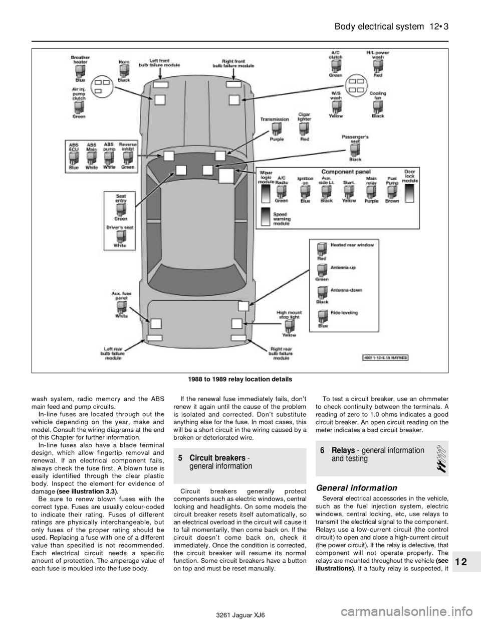
Several electrical accessories in the vehicle,
such as the fuel injection system, electric
windows, central locking, etc, use relays to
transmit the electrical signal to the component.
Relays use a low-current circuit (the control
circuit) to open and close a high-current circuit
(the power circuit). If the relay is defective, that
component will not operate properly. The
relays are mounted throughout the vehicle (see
illustrations). If a faulty relay is suspected, it
Body electrical system 12•3
12
3261 Jaguar XJ6 1988 to 1989 relay location details
Page 174 of 227
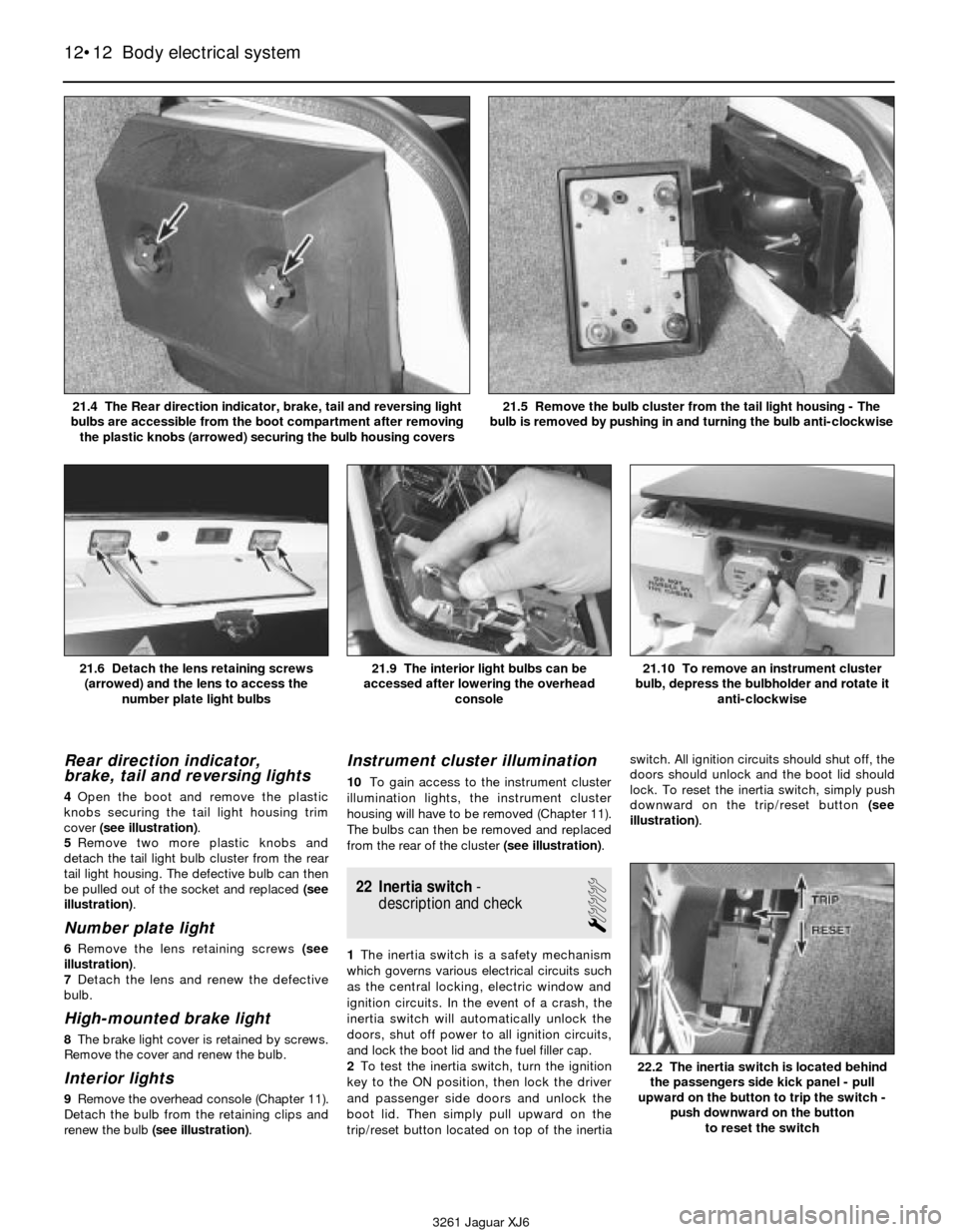
Rear direction indicator,
brake, tail and reversing lights
4Open the boot and remove the plastic
knobs securing the tail light housing trim
cover (see illustration).
5Remove two more plastic knobs and
detach the tail light bulb cluster from the rear
tail light housing. The defective bulb can then
be pulled out of the socket and replaced (see
illustration).
Number plate light
6Remove the lens retaining screws (see
illustration).
7Detach the lens and renew the defective
bulb.
High-mounted brake light
8The brake light cover is retained by screws.
Remove the cover and renew the bulb.
Interior lights
9Remove the overhead console (Chapter 11).
Detach the bulb from the retaining clips and
renew the bulb (see illustration).
Instrument cluster illumination
10To gain access to the instrument cluster
illumination lights, the instrument cluster
housing will have to be removed (Chapter 11).
The bulbs can then be removed and replaced
from the rear of the cluster (see illustration).
22 Inertia switch-
description and check
1
1The inertia switch is a safety mechanism
which governs various electrical circuits such
as the central locking, electric window and
ignition circuits. In the event of a crash, the
inertia switch will automatically unlock the
doors, shut off power to all ignition circuits,
and lock the boot lid and the fuel filler cap.
2To test the inertia switch, turn the ignition
key to the ON position, then lock the driver
and passenger side doors and unlock the
boot lid. Then simply pull upward on the
trip/reset button located on top of the inertiaswitch. All ignition circuits should shut off, the
doors should unlock and the boot lid should
lock. To reset the inertia switch, simply push
downward on the trip/reset button (see
illustration).
12•12 Body electrical system
21.6 Detach the lens retaining screws
(arrowed) and the lens to access the
number plate light bulbs21.9 The interior light bulbs can be
accessed after lowering the overhead
console21.10 To remove an instrument cluster
bulb, depress the bulbholder and rotate it
anti-clockwise
3261 Jaguar XJ6 21.4 The Rear direction indicator, brake, tail and reversing light
bulbs are accessible from the boot compartment after removing
the plastic knobs (arrowed) securing the bulb housing covers
21.5 Remove the bulb cluster from the tail light housing - The
bulb is removed by pushing in and turning the bulb anti-clockwise
22.2 The inertia switch is located behind
the passengers side kick panel - pull
upward on the button to trip the switch -
push downward on the button
to reset the switch