drain bolt JAGUAR XJ6 1997 2.G Workshop Manual
[x] Cancel search | Manufacturer: JAGUAR, Model Year: 1997, Model line: XJ6, Model: JAGUAR XJ6 1997 2.GPages: 227, PDF Size: 7.2 MB
Page 7 of 227
3261 Jaguar XJ6
Roadside repairs0•7
When jump-starting a car using a
booster battery, observe the following
precautions:
4Before connecting the booster
battery, make sure that the ignition
is switched off.
4Ensure that all electrical equipment
(lights, heater, wipers, etc) is
switched off.
4Take note of any special precautions
printed on the battery case.4Make sure that the booster battery
is the same voltage as the
discharged one in the vehicle.
4If the battery is being jump-started
from the battery in another vehicle,
the two vehicles MUST NOT TOUCH
each other.
4Make sure that the transmission is in
neutral (or PARK, in the case of
automatic transmission).
Jump starting will get you
out of trouble, but you must
correct whatever made the
battery go flat in the first
place. There are three possibilities:
1) The battery has been drained by
repeated attempts to start, or by
leaving the lights on.
2) The charging system is not working
properly (alternator drivebelt slack or
broken, alternator wiring fault or
alternator itself faulty).
3) The battery itself is at fault (electrolyte
low, or battery worn out).
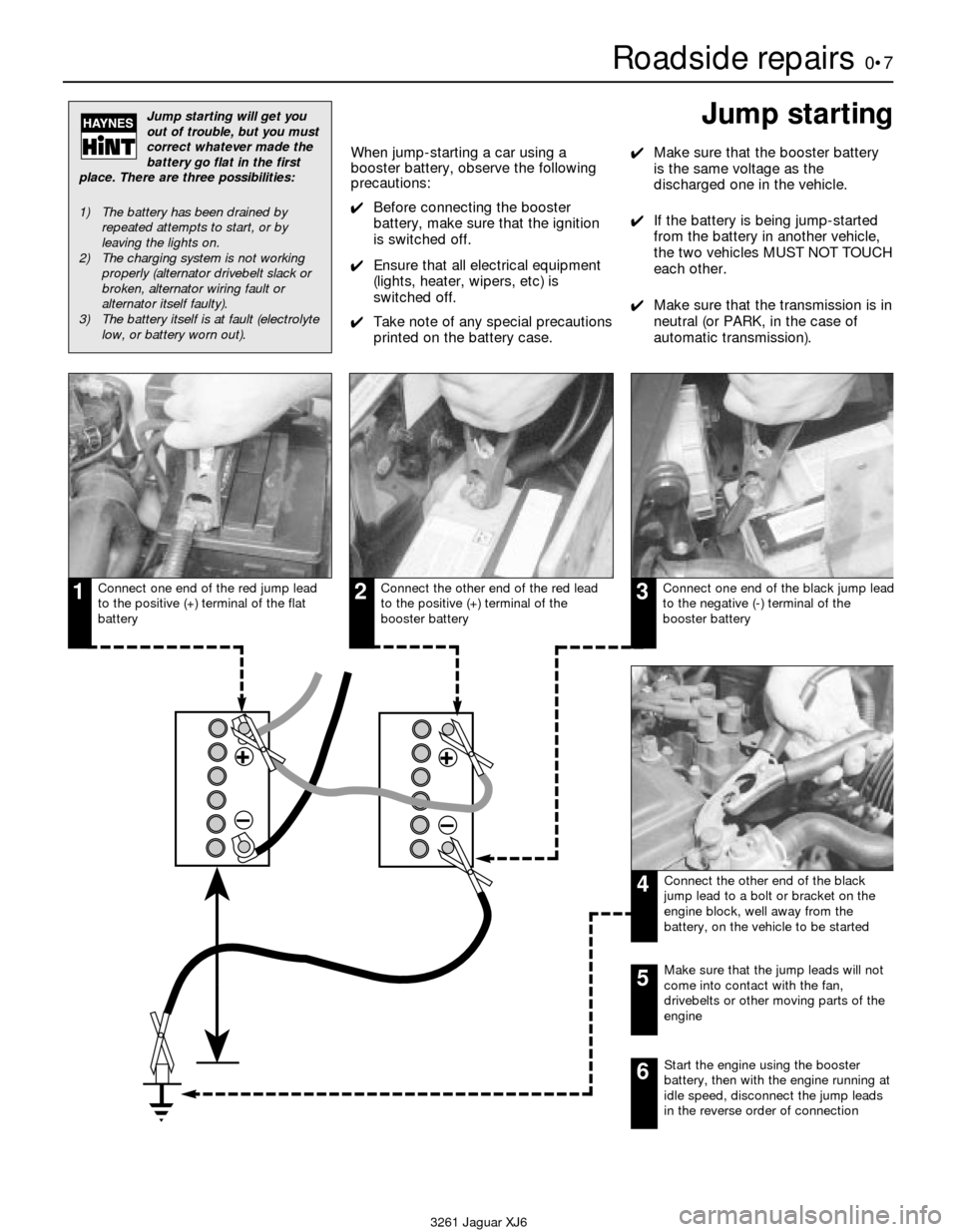
Connect one end of the red jump lead
to the positive (+) terminal of the flat
batteryConnect the other end of the red lead
to the positive (+) terminal of the
booster batteryConnect one end of the black jump lead
to the negative (-) terminal of the
booster battery
Connect the other end of the black
jump lead to a bolt or bracket on the
engine block, well away from the
battery, on the vehicle to be started
123
4
Make sure that the jump leads will not
come into contact with the fan,
drivebelts or other moving parts of the
engine5
Start the engine using the booster
battery, then with the engine running at
idle speed, disconnect the jump leads
in the reverse order of connection6
Jump starting
Page 18 of 227
Lubricants and fluids
Refer to “Weekly checks”
Capacities
Engine oil
Including oil filter . . . . . . . . . . . . . . . . . . . . . . . . . . . . . . . . . . . . . . . . . . . 8.0 litres
Cooling system
All models (approximate):
From dry . . . . . . . . . . . . . . . . . . . . . . . . . . . . . . . . . . . . . . . . . . . . . . . 12.8 litres
Drain and refill . . . . . . . . . . . . . . . . . . . . . . . . . . . . . . . . . . . . . . . . . . . 9.2 litres
Transmission
Automatic transmission (approximate):
From dry:
3.2 litre model . . . . . . . . . . . . . . . . . . . . . . . . . . . . . . . . . . . . . . . . . 7.4 litres
3.6 and 4.0 litre models . . . . . . . . . . . . . . . . . . . . . . . . . . . . . . . . . 8.0 litres
Drain and refill . . . . . . . . . . . . . . . . . . . . . . . . . . . . . . . . . . . . . . . . . . . 3.0 litres
Differential
All models (approximate) . . . . . . . . . . . . . . . . . . . . . . . . . . . . . . . . . . . . 2.1 litres
Cooling system
Antifreeze mixture:
50% antifreeze . . . . . . . . . . . . . . . . . . . . . . . . . . . . . . . . . . . . . . . . . . Protection down to -37°C (5°F)
55% antifreeze . . . . . . . . . . . . . . . . . . . . . . . . . . . . . . . . . . . . . . . . . . Protection down to -45°C (-22°F)
Note:Refer to antifreeze manufacturer for latest recommendations.
Ignition system
Spark plugs:
Type:
3.2 litre model . . . . . . . . . . . . . . . . . . . . . . . . . . . . . . . . . . . . . . . . . RC12YCC
3.6 and 4.0 litre models . . . . . . . . . . . . . . . . . . . . . . . . . . . . . . . . . RC9YCC
Electrode gap . . . . . . . . . . . . . . . . . . . . . . . . . . . . . . . . . . . . . . . . . . . 0.9 mm
*The spark plug gap quoted is that recommended by Champion
for their specified plug listed above. If spark plugs of any other type
are to be fitted, refer to their manufacturer’s recommendations.
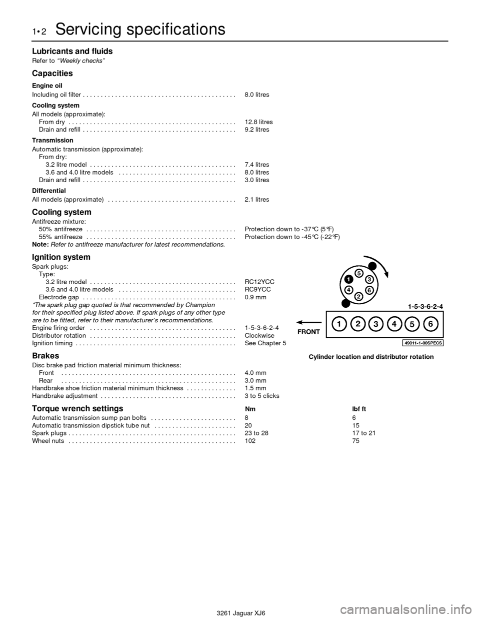
Engine firing order . . . . . . . . . . . . . . . . . . . . . . . . . . . . . . . . . . . . . . . . . 1-5-3-6-2-4
Distributor rotation . . . . . . . . . . . . . . . . . . . . . . . . . . . . . . . . . . . . . . . . . Clockwise
Ignition timing . . . . . . . . . . . . . . . . . . . . . . . . . . . . . . . . . . . . . . . . . . . . . See Chapter 5
Brakes
Disc brake pad friction material minimum thickness:
Front . . . . . . . . . . . . . . . . . . . . . . . . . . . . . . . . . . . . . . . . . . . . . . . . . 4.0 mm
Rear . . . . . . . . . . . . . . . . . . . . . . . . . . . . . . . . . . . . . . . . . . . . . . . . . 3.0 mm
Handbrake shoe friction material minimum thickness . . . . . . . . . . . . . . 1.5 mm
Handbrake adjustment . . . . . . . . . . . . . . . . . . . . . . . . . . . . . . . . . . . . . . 3 to 5 clicks
Torque wrench settingsNm lbf ft
Automatic transmission sump pan bolts . . . . . . . . . . . . . . . . . . . . . . . . 8 6
Automatic transmission dipstick tube nut . . . . . . . . . . . . . . . . . . . . . . . 20 15
Spark plugs . . . . . . . . . . . . . . . . . . . . . . . . . . . . . . . . . . . . . . . . . . . . . . . 23 to 28 17 to 21
Wheel nuts . . . . . . . . . . . . . . . . . . . . . . . . . . . . . . . . . . . . . . . . . . . . . . . 102 75
1•2Servicing specifications
3261 Jaguar XJ6
Cylinder location and distributor rotation
Page 26 of 227
never ingest it. Wear protective safety glasses
when working near the battery. Keep children
away from the battery.
5Note the external condition of the battery. If
the positive terminal and cable clamp on your
vehicle’s battery is equipped with a rubber
protector, make sure it isn’t torn or damaged.
It should completely cover the terminal. Look
for any corroded or loose connections, cracks
in the case or cover or loose hold-down
clamps. Also check the entire length of each
cable for cracks and frayed conductors.
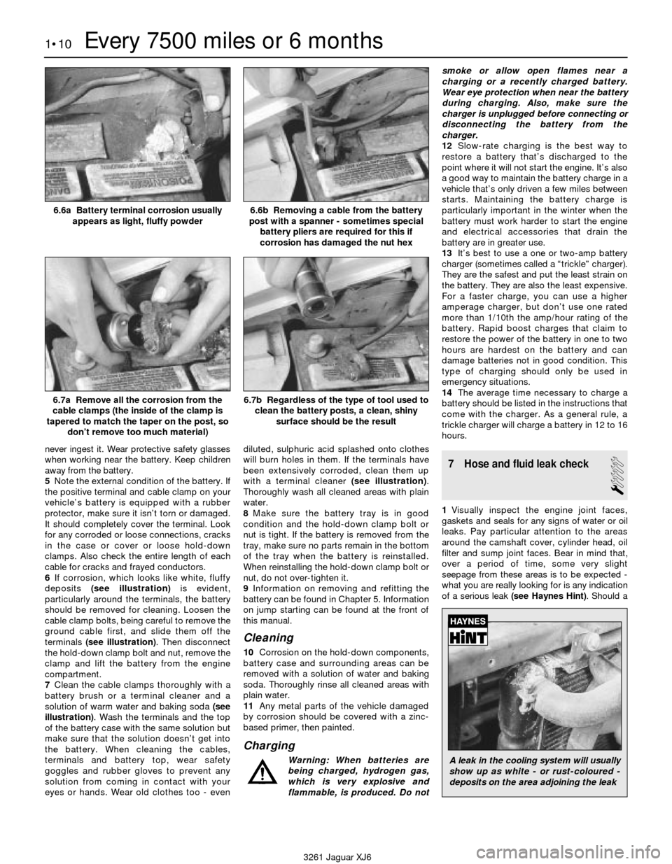
6If corrosion, which looks like white, fluffy
deposits (see illustration)is evident,
particularly around the terminals, the battery
should be removed for cleaning. Loosen the
cable clamp bolts, being careful to remove the
ground cable first, and slide them off the
terminals (see illustration). Then disconnect
the hold-down clamp bolt and nut, remove the
clamp and lift the battery from the engine
compartment.
7Clean the cable clamps thoroughly with a
battery brush or a terminal cleaner and a
solution of warm water and baking soda (see
illustration). Wash the terminals and the top
of the battery case with the same solution but
make sure that the solution doesn’t get into
the battery. When cleaning the cables,
terminals and battery top, wear safety
goggles and rubber gloves to prevent any
solution from coming in contact with your
eyes or hands. Wear old clothes too - evendiluted, sulphuric acid splashed onto clothes
will burn holes in them. If the terminals have
been extensively corroded, clean them up
with a terminal cleaner (see illustration).
Thoroughly wash all cleaned areas with plain
water.
8Make sure the battery tray is in good
condition and the hold-down clamp bolt or
nut is tight. If the battery is removed from the
tray, make sure no parts remain in the bottom
of the tray when the battery is reinstalled.
When reinstalling the hold-down clamp bolt or
nut, do not over-tighten it.
9Information on removing and refitting the
battery can be found in Chapter 5. Information
on jump starting can be found at the front of
this manual.
Cleaning
10Corrosion on the hold-down components,
battery case and surrounding areas can be
removed with a solution of water and baking
soda. Thoroughly rinse all cleaned areas with
plain water.
11Any metal parts of the vehicle damaged
by corrosion should be covered with a zinc-
based primer, then painted.
Charging
Warning: When batteries are
being charged, hydrogen gas,
which is very explosive and
flammable, is produced. Do notsmoke or allow open flames near a
charging or a recently charged battery.
Wear eye protection when near the battery
during charging. Also, make sure the
charger is unplugged before connecting or
disconnecting the battery from the
charger.
12Slow-rate charging is the best way to
restore a battery that’s discharged to the
point where it will not start the engine. It’s also
a good way to maintain the battery charge in a
vehicle that’s only driven a few miles between
starts. Maintaining the battery charge is
particularly important in the winter when the
battery must work harder to start the engine
and electrical accessories that drain the
battery are in greater use.
13It’s best to use a one or two-amp battery
charger (sometimes called a “trickle” charger).
They are the safest and put the least strain on
the battery. They are also the least expensive.
For a faster charge, you can use a higher
amperage charger, but don’t use one rated
more than 1/10th the amp/hour rating of the
battery. Rapid boost charges that claim to
restore the power of the battery in one to two
hours are hardest on the battery and can
damage batteries not in good condition. This
type of charging should only be used in
emergency situations.
14The average time necessary to charge a
battery should be listed in the instructions that
come with the charger. As a general rule, a
trickle charger will charge a battery in 12 to 16
hours.
7 Hose and fluid leak check
1
1Visually inspect the engine joint faces,
gaskets and seals for any signs of water or oil
leaks. Pay particular attention to the areas
around the camshaft cover, cylinder head, oil
filter and sump joint faces. Bear in mind that,
over a period of time, some very slight
seepage from these areas is to be expected -
what you are really looking for is any indication
of a serious leak (see Haynes Hint). Should a
1•10Every 7500 miles or 6 months
6.6a Battery terminal corrosion usually
appears as light, fluffy powder6.6b Removing a cable from the battery
post with a spanner - sometimes special
battery pliers are required for this if
corrosion has damaged the nut hex
6.7a Remove all the corrosion from the
cable clamps (the inside of the clamp is
tapered to match the taper on the post, so
don’t remove too much material)6.7b Regardless of the type of tool used to
clean the battery posts, a clean, shiny
surface should be the result
3261 Jaguar XJ6
A leak in the cooling system will usually
show up as white - or rust-coloured -
deposits on the area adjoining the leak
Page 35 of 227
26 Automatic transmission fluid
and filter renewal
2
1At the specified time intervals, the
transmission fluid should be drained and
renewed. Since the fluid will remain hot long
after driving, perform this procedure only after
the engine has cooled down completely.
2Before beginning work, purchase the
specified transmission fluid and a new filter.
3Other tools necessary for this job include
axle stands to support the vehicle in a raised
position, a drain pan capable of holding at
least eight pints, newspapers and clean rags.4Raise the vehicle and support it securely on
axle stands.
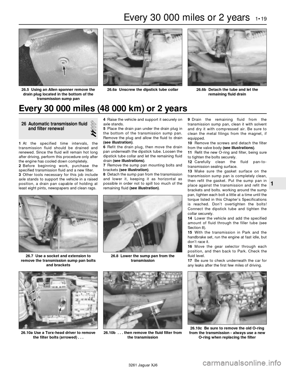
5Place the drain pan under the drain plug in
the bottom of the transmission sump pan.
Remove the plug and allow the fluid to drain
(see illustration).
6Refit the drain plug, then move the drain
pan underneath the dipstick tube. Loosen the
dipstick tube collar and let the remaining fluid
drain (see illustrations).
7Remove the sump pan mounting bolts and
brackets (see illustration).
8Detach the sump pan from the transmission
and lower it, keeping it as horizontal as
possible in order not to spill too much of the
remaining fluid (see illustration).9Drain the remaining fluid from the
transmission sump pan, clean it with solvent
and dry it with compressed air. Be sure to
clean the metal filings from the magnet, if
equipped.
10Remove the screws and detach the filter
from the valve body (see illustrations).
11Refit the new O-ring and filter, being sure
to tighten the bolts securely.
12Carefully clean the fluid pan-to-
transmission sealing surface.
13Make sure the gasket surface on the
transmission sump pan is completely clean,
then refit the gasket. Put the sump pan in
place against the transmission and refit the
brackets and bolts. working around the sump
pan, tighten each bolt a little at a time until the
torque listed in this Chapter’s Specifications
is reached. Don’t overtighten the bolts!
Connect the dipstick tube and tighten the
collar securely.
14Lower the vehicle and add the specified
amount of fluid through the filler tube (see
Section 8).
15With the transmission in Park and the
handbrake set, run the engine at fast idle, but
don’t race it.
16Move the gear selector through each
position, and then back to Park. Check the
fluid level.
17Be sure to check underneath the car for
any leaks after the first few miles of driving.
Every 30 000 miles (48 000 km) or 2 years
Every 30 000 miles or 2 years 1•19
1
26.6a Unscrew the dipstick tube collar26.6b Detach the tube and let the
remaining fluid drain
26.7 Use a socket and extension to
remove the transmission sump pan bolts
and brackets26.8 Lower the sump pan from the
transmission
26.10a Use a Torx-head driver to remove
the filter bolts (arrowed) . . .
3261 Jaguar XJ6
26.5 Using an Allen spanner remove the
drain plug located in the bottom of the
transmission sump pan
26.10b . . . then remove the fluid filter from
the transmission26.10c Be sure to remove the old O-ring
from the transmission - always use a new
O-ring when replacing the filter
Page 50 of 227
11 Cylinder head-
removal and refitting
4
Note:The engine must be completely cool
before beginning this procedure.
Removal
1Disconnect the battery negative cable.
Caution: If the stereo in your vehicle is
equipped with an anti-theft system, make
sure you have the correct activation code
before disconnecting the battery.
2Drain the coolant from the engine block and
radiator (see Chapter 1).
3Drain the engine oil and remove the oil filter
(see Chapter 1).
4Remove the bonnet for easier access, if
necessary (see Chapter 11).
5Remove the intake manifold (see Section 5).
6Remove the exhaust manifolds (Section 6).
7Remove the valve cover (see Section 4).
8Refer to Section 3 and Position the engine
at TDC for cylinder number 1. Remove the
distributor (see Chapter 5).
9Remove the camshafts and sprockets (see
Section 10). Place the upper chain between
the two upper chain guides and wrap a large
rubber band around the two guides, retaining
the chain and guides.
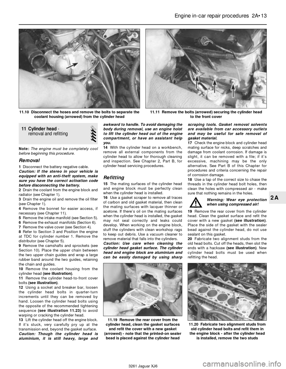
10Remove the coolant housing from the
cylinder head (see illustration).
11Remove the cylinder head-to-front cover
bolts (see illustration).
12Using a socket and breaker bar, loosen
the cylinder head bolts in quarter-turn
increments until they can be removed by
hand. Loosen the cylinder head bolts using
the opposite of the recommended tightening
sequence (see illustration 11.23)to avoid
warping or cracking the cylinder head.
13Lift the cylinder head off the engine block.
If it’s stuck, very carefully pry up at the
transmission end, beyond the gasket surface.
Caution: Though the cylinder head is
aluminium, it is still heavy, large andawkward to handle. To avoid damaging the
body during removal, use an engine hoist
to lift the cylinder head out of the engine
compartment, or have an assistant help
you.
14With the cylinder head on a workbench,
remove all external components from the
cylinder head to allow for thorough cleaning
and inspection. See Chapter 2, Part B, for
cylinder head servicing procedures.
Refitting
15The mating surfaces of the cylinder head
and engine block must be perfectly clean
when the cylinder head is installed.
16Use a gasket scraper to remove all traces
of carbon and old gasket material, then clean
the mating surfaces with lacquer thinner or
acetone. If there’s oil on the mating surfaces
when the cylinder head is installed, the gasket
may not seal correctly and leaks could
develop. When working on the engine block,
stuff the cylinders with clean workshop rags
to keep out debris. Use a vacuum cleaner to
remove material that falls into the cylinders.
Caution: Use care when cleaning the
cylinder head gasket surface. The cylinder
head and engine block are aluminium and
can be easily damaged by using sharpscraping tools. Gasket removal solvents
are available from car accessory outlets
and may be useful for safe removal of
gasket material.
17Check the engine block and cylinder head
mating surface for nicks, deep scratches and
damage from coolant corrosion. If damage is
slight, it can be removed with a file; if it’s
excessive, machining may be the only
alternative. See Part B of this Chapter for
procedures and criteria concerning the repair
of corrosion damage.
18Use a tap of the correct size to chase the
threads in the cylinder head bolt holes, then
clean the holes with compressed air - make
sure that nothing remains in the holes.
Warning: Wear eye protection
when using compressed air!
19Remove the rear cover from the cylinder
head. Clean the gasket surface and refit the
cover with a new gasket (see illustration).
Place the side of the gasket with the sealer
bead against the cylinder head, do not use
sealant on this gasket.
20Fabricate two alignment studs from the
old head bolts. Cut off the heads, then slot the
ends with a hacksaw (see illustration). New
cylinder head bolts must be used when
refitting the head.
Engine in-car repair procedures 2A•13
2A
11.19 Remove the rear cover from the
cylinder head, clean the gasket surfaces
and refit the cover with a new gasket
(arrowed) - note that the printed-on sealer
bead is placed against the cylinder head11.20 Fabricate two alignment studs from
old cylinder head bolts and refit them in
the engine block - after the cylinder head
is installed, remove the two studs
3261 Jaguar XJ6 11.10 Disconnect the hoses and remove the bolts to separate the
coolant housing (arrowed) from the cylinder head
11.11 Remove the bolts (arrowed) securing the cylinder head
to the front cover
Page 51 of 227
21There are variations in cooling holes in
some models. Before refitting the cylinder
head gasket, carefully check all of the
passages and bolt holes in the new cylinder
head gasket to be sure it matches your engine
block. Also make sure the new cylinder head
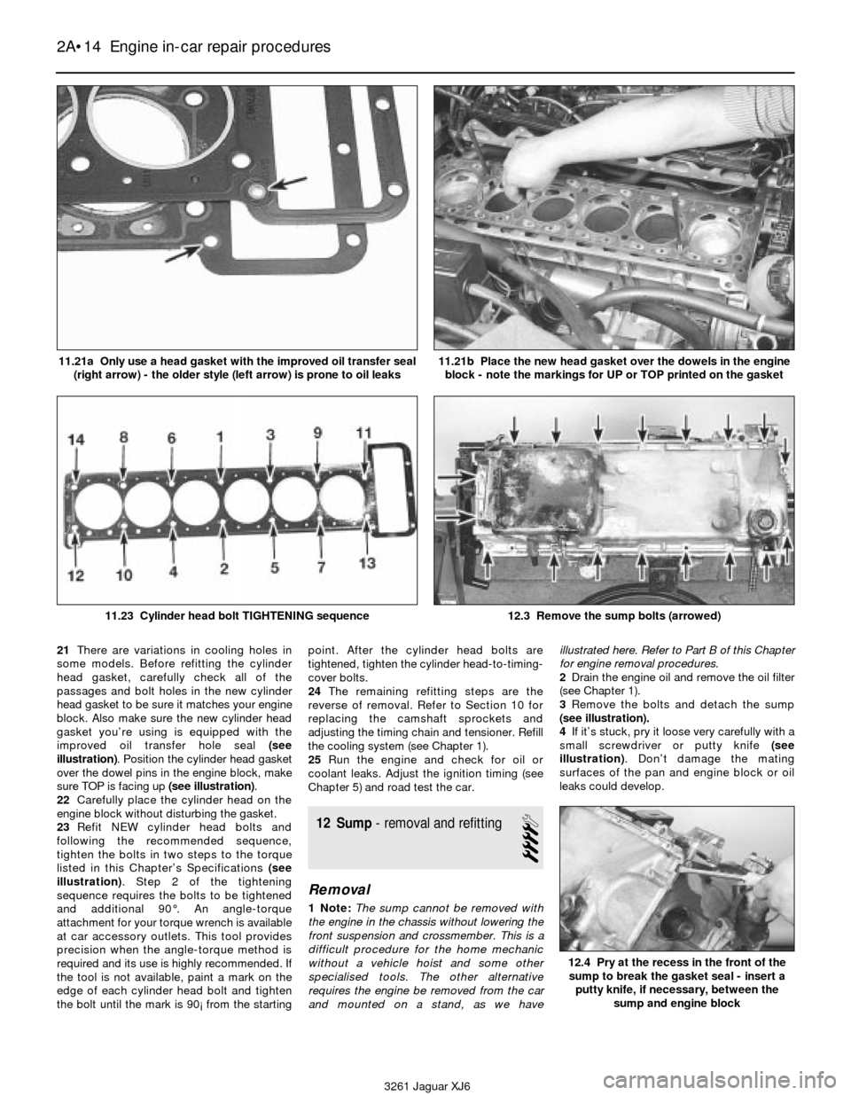
gasket you’re using is equipped with the
improved oil transfer hole seal (see
illustration). Position the cylinder head gasket
over the dowel pins in the engine block, make
sure TOP is facing up (see illustration).
22Carefully place the cylinder head on the
engine block without disturbing the gasket.
23Refit NEW cylinder head bolts and
following the recommended sequence,
tighten the bolts in two steps to the torque
listed in this Chapter’s Specifications(see
illustration). Step 2 of the tightening
sequence requires the bolts to be tightened
and additional 90°. An angle-torque
attachment for your torque wrench is available
at car accessory outlets. This tool provides
precision when the angle-torque method is
required and its use is highly recommended. If
the tool is not available, paint a mark on the
edge of each cylinder head bolt and tighten
the bolt until the mark is 90¡ from the startingpoint. After the cylinder head bolts are
tightened, tighten the cylinder head-to-timing-
cover bolts.
24The remaining refitting steps are the
reverse of removal. Refer to Section 10 for
replacing the camshaft sprockets and
adjusting the timing chain and tensioner. Refill
the cooling system (see Chapter 1).
25Run the engine and check for oil or
coolant leaks. Adjust the ignition timing (see
Chapter 5) and road test the car.
12 Sump- removal and refitting
4
Removal
1 Note:The sump cannot be removed with
the engine in the chassis without lowering the
front suspension and crossmember. This is a
difficult procedure for the home mechanic
without a vehicle hoist and some other
specialised tools. The other alternative
requires the engine be removed from the car
and mounted on a stand, as we haveillustrated here. Refer to Part B of this Chapter
for engine removal procedures.
2Drain the engine oil and remove the oil filter
(see Chapter 1).
3Remove the bolts and detach the sump
(see illustration).
4If it’s stuck, pry it loose very carefully with a
small screwdriver or putty knife (see
illustration). Don’t damage the mating
surfaces of the pan and engine block or oil
leaks could develop.
2A•14 Engine in-car repair procedures
3261 Jaguar XJ6 11.21a Only use a head gasket with the improved oil transfer seal
(right arrow) - the older style (left arrow) is prone to oil leaks
11.21b Place the new head gasket over the dowels in the engine
block - note the markings for UP or TOP printed on the gasket
11.23 Cylinder head bolt TIGHTENING sequence12.3 Remove the sump bolts (arrowed)
12.4 Pry at the recess in the front of the
sump to break the gasket seal - insert a
putty knife, if necessary, between the
sump and engine block
Page 52 of 227

Refitting
5Remove all traces of old gasket material
and sealant from the engine block and sump.
Clean the mating surface with lacquer thinner
or acetone.
Caution: Do not use a sharp scraping tool.
Both the sump and the engine block are
aluminium and could be easily damaged.
6Make sure the threaded bolt holes in the
engine block and bellhousing are clean.
7Inspect the flange of the sump for any
cracks, pits or scratches that could cause an
oil leak.
8Remove the baffle plate at the rear of the
sump (see illustration). Clean the sump area
and the baffle, then refit the baffle.
9Inspect the oil pump pickup tube for
cracks, or foreign material blocking the screen
(see illustration).
10Apply a bead of RTV sealant to the sump
flange(see illustration). Note:The sump
must be installed within 5 minutes of sealer
application.
11Carefully position the sump on the engine
block and push it toward the transmission
adapter plate as you press it against the
engine block. Loosely refit four bolts, two on
each side of the sump. Tighten the four bolts
in a criss-cross pattern to the torque listed in
this Chapter’s Specifications, then loosen
each bolt 90°.
12Refit the two engine adapter-to-sump
bolts. Tighten the two bolts to the torque
listed in this Chapter’s Specifications, then
loosen each one 180°.
13Refit the remainder of the sump-to-engine
block bolts hand tight until all are installed,
then tighten them to the torque listed in this
Chapter’s Specifications. Lastly, tighten the
two adapter-to-sump bolts to the torque
listed in this Chapter’s Specifications.
Caution: Failure to follow this tightening
procedure could stress or possibly crack
the adapter plate.
14The remainder of refitting is the reverse of
removal. Be sure to add oil and refit a new oil
filter.
15Run the engine and check for oil pressure
and leaks.13 Oil pump- removal,
inspection and refitting
4
Removal
1Remove the sump (see Section 12).
2Unbolt the oil pickup tube and oil transfer
housing from the engine block (see
illustration). Note:Have a drain pan under the
transfer housing, as oil may drip out when the
housing is loosened from the engine block.
3Carefully pull the transfer housing and
transfer tubes to the rear to separate them
from the oil pump body.
4Bend back the locking tabs and remove thethree bolts retaining the oil pump drive
sprocket to the oil pump (see illustration).
Pull the chain and sprocket from the front of
the pump. Note:There are shims between the
sprocket and the pump. Collect them while
pulling off the sprocket.
5Remove the bolts and detach the oil pump
from the engine.
6Remove all traces of sealant and old gasket
material from the oil pump body and engine
block, then clean the mating surfaces with
lacquer thinner or acetone.
7Remove the screws and separate the front
and rear pump covers from the body. Lift out
the drive and driven rotors (see illustrations).
Note:Mark the front face of each rotor before
removing them.
Engine in-car repair procedures 2A•15
2A
12.8 Remove the bolts (arrowed) and the
sheetmetal baffle plate - clean the sump
area of the sump with the baffle removed12.9 Lubrication system components
A Oil pump
B Transfer tubesC Transfer housing
D Oil pump pickup12.10 Apply a bead of RTV sealant around
the perimeter of the sump mounting
flange, be sure to run the bead around the
outside all bolt the holes
13.7a Remove the bolts and separate the
front and rear pump covers13.7b Remove the outer rotor (A)
and inner rotor (B)
13.2 Unbolt the oil pump pickup (A) and
the bolts (B) retaining the transfer
assembly (C) to the engine block13.4 Pry back the locking tabs and remove
the three bolts retaining the oil pump drive
sprocket to the pump
3261 Jaguar XJ6
Page 55 of 227

6Slowly and carefully press the seal and
retainer squarely onto the crankshaft (see
illustration). The plastic sleeve may be
pushed out as the retainer seats on the engine
block. Remove the plastic sleeve.
7Refit and tighten the retainer bolts to the
torque listed in this Chapter’s Specifications.
8The remaining steps are the reverse of
removal.
16 Engine mounts-
check and renewal
3
1Engine mounts seldom require attention,
but broken or deteriorated mounts should be
renewed immediately or the added strain
placed on the driveline components may
cause damage or wear.
Check
2During the check, the engine must be
raised to remove the weight from the mounts.3Raise the car and support it securely on
axle stands, then position a jack under the
engine sump. Place a large wood block
between the jack head and the sump, then
carefully raise the engine just enough to take
the weight off the mounts. Do not position the
wood block under the drain plug.
Warning: DO NOT place any part
of your body under the engine
when it’s supported by a jack!
4Check the front mounts to see if the rubber
is cracked, hardened or separated from the
metal plates. Sometimes the rubber will split
down the centre.
5Check for relative movement between the
mount plates and the engine or frame (use a
large screwdriver or pry bar to attempt to
move the mounts). If movement is noted,
lower the engine and tighten the mount
fasteners.
6Rubber preservative should be applied to
the mounts to slow deterioration.
Renewal
7Disconnect the battery negative cable.
Caution: If the stereo in your vehicle is
equipped with an anti-theft system, make
sure you have the correct activation code
before disconnecting the battery.
8Raise the car and support it securely on
axle stands. Support the engine as described
in paragraph 3.
Caution: Ensure the cooling fan doesn’t hit
the shroud as the engine is raised.
9To remove either engine mount, remove the
nut from the engine bracket, then raise the
engine (see illustration).
10From underneath the car, lower the
steering gear (see Chapter 10) for access to
the nut retaining the insulator to the chassis
bracket.
11Refitting is the reverse of removal. Use
thread-locking compound on the mount
bolts/nuts and be sure to tighten them
securely.
12See Chapter 7 for transmission mount
renewal.
2A•18 Engine in-car repair procedures
3261 Jaguar XJ6 15.6 Refit the retainer and oil seal onto the crankshaft
16.9 Front engine mount (A)
and retaining nut to engine bracket (B)
Page 59 of 227
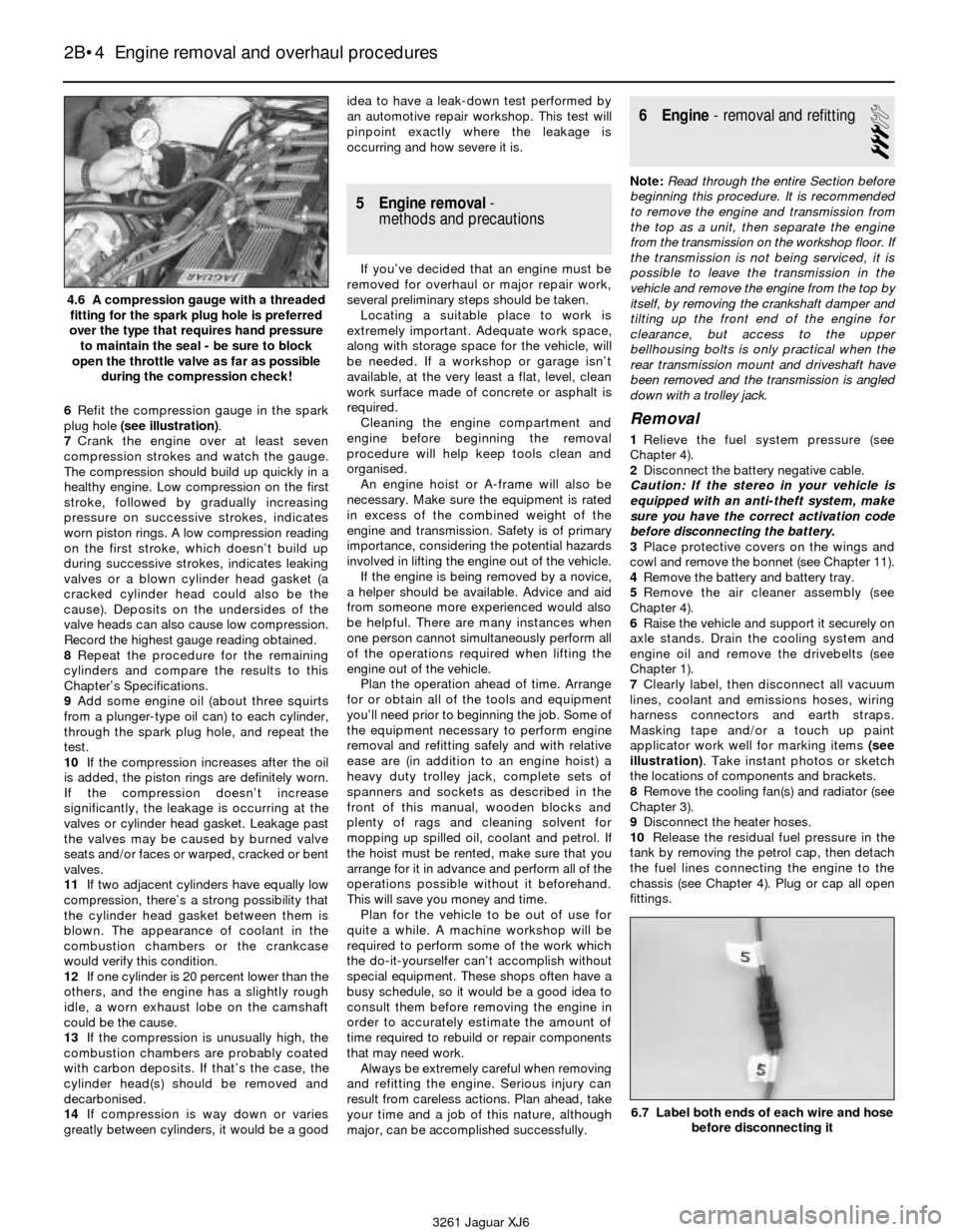
6Refit the compression gauge in the spark
plug hole (see illustration).
7Crank the engine over at least seven
compression strokes and watch the gauge.
The compression should build up quickly in a
healthy engine. Low compression on the first
stroke, followed by gradually increasing
pressure on successive strokes, indicates
worn piston rings. A low compression reading
on the first stroke, which doesn’t build up
during successive strokes, indicates leaking
valves or a blown cylinder head gasket (a
cracked cylinder head could also be the
cause). Deposits on the undersides of the
valve heads can also cause low compression.
Record the highest gauge reading obtained.
8Repeat the procedure for the remaining
cylinders and compare the results to this
Chapter’s Specifications.
9Add some engine oil (about three squirts
from a plunger-type oil can) to each cylinder,
through the spark plug hole, and repeat the
test.
10If the compression increases after the oil
is added, the piston rings are definitely worn.
If the compression doesn’t increase
significantly, the leakage is occurring at the
valves or cylinder head gasket. Leakage past
the valves may be caused by burned valve
seats and/or faces or warped, cracked or bent
valves.
11If two adjacent cylinders have equally low
compression, there’s a strong possibility that
the cylinder head gasket between them is
blown. The appearance of coolant in the
combustion chambers or the crankcase
would verify this condition.
12If one cylinder is 20 percent lower than the
others, and the engine has a slightly rough
idle, a worn exhaust lobe on the camshaft
could be the cause.
13If the compression is unusually high, the
combustion chambers are probably coated
with carbon deposits. If that’s the case, the
cylinder head(s) should be removed and
decarbonised.
14If compression is way down or varies
greatly between cylinders, it would be a goodidea to have a leak-down test performed by
an automotive repair workshop. This test will
pinpoint exactly where the leakage is
occurring and how severe it is.
5 Engine removal-
methods and precautions
If you’ve decided that an engine must be
removed for overhaul or major repair work,
several preliminary steps should be taken.
Locating a suitable place to work is
extremely important. Adequate work space,
along with storage space for the vehicle, will
be needed. If a workshop or garage isn’t
available, at the very least a flat, level, clean
work surface made of concrete or asphalt is
required.
Cleaning the engine compartment and
engine before beginning the removal
procedure will help keep tools clean and
organised.
An engine hoist or A-frame will also be
necessary. Make sure the equipment is rated
in excess of the combined weight of the
engine and transmission. Safety is of primary
importance, considering the potential hazards
involved in lifting the engine out of the vehicle.
If the engine is being removed by a novice,
a helper should be available. Advice and aid
from someone more experienced would also
be helpful. There are many instances when
one person cannot simultaneously perform all
of the operations required when lifting the
engine out of the vehicle.
Plan the operation ahead of time. Arrange
for or obtain all of the tools and equipment
you’ll need prior to beginning the job. Some of
the equipment necessary to perform engine
removal and refitting safely and with relative
ease are (in addition to an engine hoist) a
heavy duty trolley jack, complete sets of
spanners and sockets as described in the
front of this manual, wooden blocks and
plenty of rags and cleaning solvent for
mopping up spilled oil, coolant and petrol. If
the hoist must be rented, make sure that you
arrange for it in advance and perform all of the
operations possible without it beforehand.
This will save you money and time.
Plan for the vehicle to be out of use for
quite a while. A machine workshop will be
required to perform some of the work which
the do-it-yourselfer can’t accomplish without
special equipment. These shops often have a
busy schedule, so it would be a good idea to
consult them before removing the engine in
order to accurately estimate the amount of
time required to rebuild or repair components
that may need work.
Always be extremely careful when removing
and refitting the engine. Serious injury can
result from careless actions. Plan ahead, take
your time and a job of this nature, although
major, can be accomplished successfully.
6 Engine- removal and refitting
3
Note:Read through the entire Section before
beginning this procedure. It is recommended
to remove the engine and transmission from
the top as a unit, then separate the engine
from the transmission on the workshop floor. If
the transmission is not being serviced, it is
possible to leave the transmission in the
vehicle and remove the engine from the top by
itself, by removing the crankshaft damper and
tilting up the front end of the engine for
clearance,but access to the upper
bellhousing bolts is only practical when the
rear transmission mount and driveshaft have
been removed and the transmission is angled
down with a trolley jack.
Removal
1Relieve the fuel system pressure (see
Chapter 4).
2Disconnect the battery negative cable.
Caution: If the stereo in your vehicle is
equipped with an anti-theft system, make
sure you have the correct activation code
before disconnecting the battery.
3Place protective covers on the wings and
cowl and remove the bonnet (see Chapter 11).
4Remove the battery and battery tray.
5Remove the air cleaner assembly (see
Chapter 4).
6Raise the vehicle and support it securely on
axle stands. Drain the cooling system and
engine oil and remove the drivebelts (see
Chapter 1).
7Clearly label, then disconnect all vacuum
lines, coolant and emissions hoses, wiring
harness connectors and earth straps.
Masking tape and/or a touch up paint
applicator work well for marking items (see
illustration). Take instant photos or sketch
the locations of components and brackets.
8Remove the cooling fan(s) and radiator (see
Chapter 3).
9Disconnect the heater hoses.
10Release the residual fuel pressure in the
tank by removing the petrol cap, then detach
the fuel lines connecting the engine to the
chassis (see Chapter 4). Plug or cap all open
fittings.
2B•4 Engine removal and overhaul procedures
4.6 A compression gauge with a threaded
fitting for the spark plug hole is preferred
over the type that requires hand pressure
to maintain the seal - be sure to block
open the throttle valve as far as possible
during the compression check!
6.7 Label both ends of each wire and hose
before disconnecting it
3261 Jaguar XJ6
Page 74 of 227
3261 Jaguar XJ6
3
Chapter 3
Cooling, heating and air conditioning systems
General
Radiator cap pressure rating . . . . . . . . . . . . . . . . . . . . . . . . . . . . . . . . . 13.5 to 117.5 psi
Thermostat rating . . . . . . . . . . . . . . . . . . . . . . . . . . . . . . . . . . . . . . . . . . 180 to 207° F
Torque wrench settingsNm lbf ft
Coolant pipe to block . . . . . . . . . . . . . . . . . . . . . . . . . . . . . . . . . . . . . . . 22 to 28 16 to 21
Fan assembly-to-drive hub nuts . . . . . . . . . . . . . . . . . . . . . . . . . . . . . . . 22 to 28 16 to 21
Fan clutch-to-fan blade bolts . . . . . . . . . . . . . . . . . . . . . . . . . . . . . . . . . 22 to 28 16 to 21
Thermostat cover bolts . . . . . . . . . . . . . . . . . . . . . . . . . . . . . . . . . . . . . . 22 to 28 16 to 21
Thermostat housing-to-block bolts . . . . . . . . . . . . . . . . . . . . . . . . . . . . 22 to 28 16 to 21
Water pump bolts . . . . . . . . . . . . . . . . . . . . . . . . . . . . . . . . . . . . . . . . . . 22 to 28 16 to 21 Air conditioning and heating system - check and maintenance . . . . 13
Air conditioning compressor - removal and refitting . . . . . . . . . . . . . 15
Air conditioning condenser - removal and refitting . . . . . . . . . . . . . . 16
Air conditioning evaporator and expansion valve - removal
and refitting . . . . . . . . . . . . . . . . . . . . . . . . . . . . . . . . . . . . . . . . . . 17
Air conditioning receiver/drier - removal and refitting . . . . . . . . . . . . 14
Antifreeze/coolant - general information . . . . . . . . . . . . . . . . . . . . . . 2
Coolant level check . . . . . . . . . . . . . . . . . . . . . . . . . . . . See Chapter 1
Coolant temperature sender unit - check and renewal . . . . . . . . . . . .9
Cooling system check . . . . . . . . . . . . . . . . . . . . . . . . . . See Chapter 1
Cooling system draining, flushing and refilling . . . . . . . . See Chapter 1
Drivebelt check, adjustment and renewal . . . . . . . . . . . See Chapter 1
Engine cooling fans - check and renewal . . . . . . . . . . . . . . . . . . . . . 4Engine oil cooler - renewal . . . . . . . . . . . . . . . . . . . . . . . . . . . . . . . . 6
General information . . . . . . . . . . . . . . . . . . . . . . . . . . . . . . . . . . . . . . 1
Heater and air conditioning blower motors -circuit check
and component renewal . . . . . . . . . . . . . . . . . . . . . . . . . . . . . . . . 10
Heater and air conditioning control assembly -
check, removal and refitting . . . . . . . . . . . . . . . . . . . . . . . . . . . . . 12
Heater core - removal and refitting . . . . . . . . . . . . . . . . . . . . . . . . . . 11
Radiator, expansion tank and coolant reservoir -
removal and refitting . . . . . . . . . . . . . . . . . . . . . . . . . . . . . . . . . . . 5
Thermostat - check and renewal . . . . . . . . . . . . . . . . . . . . . . . . . . . . 3
Underbonnet hose check and renewal . . . . . . . . . . . . . . See Chapter 1
Water pump - check . . . . . . . . . . . . . . . . . . . . . . . . . . . . . . . . . . . . . 7
Water pump and pipes - renewal . . . . . . . . . . . . . . . . . . . . . . . . . . . 8
3•1
Specifications Contents
Easy,suitable for
novice with little
experienceFairly easy,suitable
for beginner with
some experienceFairly difficult,
suitable for competent
DIY mechanic
Difficult,suitable for
experienced DIY
mechanicVery difficult,
suitable for expert DIY
or professional
Degrees of difficulty
54321
1 General information
Engine cooling system
All vehicles covered by this manual employ a
pressurised engine cooling system with
thermostatically-controlled coolant circulation.
An impeller type water pump mounted on the
front of the block pumps coolant through the
engine. The coolant flows around each cylinder
and toward the rear of the engine. Cast-in
coolant passages direct coolant around the
intake and exhaust ports, near the spark plug
areas and in proximity to the exhaust valve
guides.A wax-pellet type thermostat is located in
the thermostat housing at the front of the
engine. During warm up, the closed
thermostat prevents coolant from circulating
through the radiator. When the engine
reaches normal operating temperature, the
thermostat opens and allows hot coolant to
travel through the radiator, where it is cooled
before returning to the engine.
The cooling system is sealed by a pressure-
type radiator cap. This raises the boiling point
of the coolant, and the higher boiling point of
the coolant increases the cooling efficiency
of the radiator. If the system pressure exceeds
the cap pressure-relief value, the excess
pressure in the system forces the spring-
loaded valve inside the cap off its seat and
allows the coolant to escape through the
overflow tube into a coolant reservoir. Whenthe system cools, the excess coolant is
automatically drawn from the reservoir back
into the radiator. This type of cooling system is
known as a closed design because coolant
that escapes past the pressure cap is saved
and reused.
The Jaguar cooling system on 1988 and
1989 models has both a manifold tank and a
coolant recovery tank. The manifold tank is the
highest point in the cooling system and is the
location of the “radiator” cap (the cap is not on
the radiator). The recovery tank down in the
passenger’s footwell collects heated coolant
as described above. Models from 1990 to
1994 do not have a coolant recovery tank, but
have an enlarged manifold tank. In all models,
the recovery tank has a sensor in it to detect a
low coolant level, and the instrument panel has
a warning light to that effect.