set clock JAGUAR XJ6 1997 2.G Workshop Manual
[x] Cancel search | Manufacturer: JAGUAR, Model Year: 1997, Model line: XJ6, Model: JAGUAR XJ6 1997 2.GPages: 227, PDF Size: 7.2 MB
Page 13 of 227
3261 Jaguar XJ6
Weekly checks0•13
Power steering
fluid level
Before you start:
4Park the vehicle on level ground.
4Set the steering wheel straight-ahead.
4The engine should be turned off.
Safety first!
lThe need for frequent topping-up indicates
a leak, which should be investigated
immediately.
For the check to be
accurate, the steering must
not be turned once the
engine has been stopped.
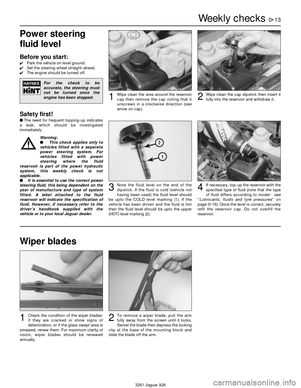
Wipe clean the area around the reservoir
cap then remove the cap noting that it
unscrews in a clockwise direction (see
arrow on cap).1Wipe clean the cap dipstick then insert it
fully into the reservoir and withdraw it.2
Note the fluid level on the end of the
dipstick. If the fluid is cold (vehicle not
having been used) the fluid level should
be upto the COLD level marking (1). If the
vehicle has been driven and the fluid is hot
then the fluid level should be upto the upper
(HOT) level marking (2).3If necessary, top-up the reservoir with the
specified type of fluid (note that the type
of fluid differs according to model - see
“Lubricants, fluids and tyre pressures” on
page 0•16). Once the level is correct, securely
refit the reservoir cap. Do not overfill the
reservoir.4
Wiper blades
Check the condition of the wiper blades:
if they are cracked or show signs of
deterioration, or if the glass swept area is
smeared, renew them. For maximum clarity of
vision, wiper blades should be renewed
annually.1To remove a wiper blade, pull the arm
fully away from the screen until it locks.
Swivel the blade then depress the locking
clip at the base of the mounting block and
slide the blade off the arm.2
Warning:
l This check applies only to
vehicles fitted with a separate
power steering system. For
vehicles fitted with power
steering where the fluid
reservoir is part of the power hydraulic
system, this weekly check is not
applicable.
l It is essential to use the correct power
steering fluid, this being dependent on the
year of manufacture and type of system
fitted. A label attached to the fluid
reservoir will indicate the specification of
fluid. However, if necessary refer to the
driver’s handbook supplied with the
vehicle or to your local Jaguar dealer.
Page 18 of 227
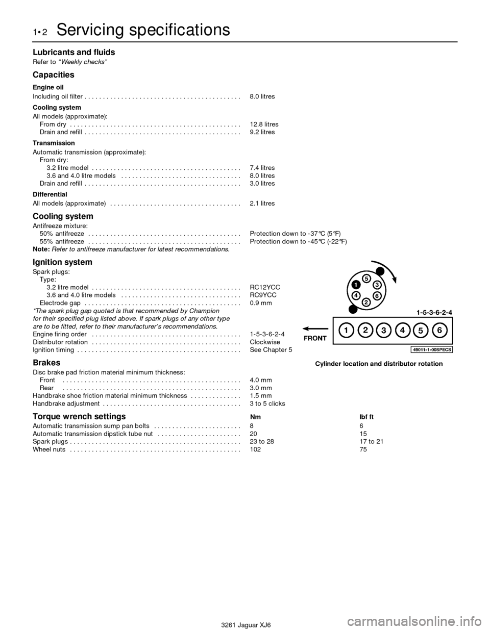
Lubricants and fluids
Refer to “Weekly checks”
Capacities
Engine oil
Including oil filter . . . . . . . . . . . . . . . . . . . . . . . . . . . . . . . . . . . . . . . . . . . 8.0 litres
Cooling system
All models (approximate):
From dry . . . . . . . . . . . . . . . . . . . . . . . . . . . . . . . . . . . . . . . . . . . . . . . 12.8 litres
Drain and refill . . . . . . . . . . . . . . . . . . . . . . . . . . . . . . . . . . . . . . . . . . . 9.2 litres
Transmission
Automatic transmission (approximate):
From dry:
3.2 litre model . . . . . . . . . . . . . . . . . . . . . . . . . . . . . . . . . . . . . . . . . 7.4 litres
3.6 and 4.0 litre models . . . . . . . . . . . . . . . . . . . . . . . . . . . . . . . . . 8.0 litres
Drain and refill . . . . . . . . . . . . . . . . . . . . . . . . . . . . . . . . . . . . . . . . . . . 3.0 litres
Differential
All models (approximate) . . . . . . . . . . . . . . . . . . . . . . . . . . . . . . . . . . . . 2.1 litres
Cooling system
Antifreeze mixture:
50% antifreeze . . . . . . . . . . . . . . . . . . . . . . . . . . . . . . . . . . . . . . . . . . Protection down to -37°C (5°F)
55% antifreeze . . . . . . . . . . . . . . . . . . . . . . . . . . . . . . . . . . . . . . . . . . Protection down to -45°C (-22°F)
Note:Refer to antifreeze manufacturer for latest recommendations.
Ignition system
Spark plugs:
Type:
3.2 litre model . . . . . . . . . . . . . . . . . . . . . . . . . . . . . . . . . . . . . . . . . RC12YCC
3.6 and 4.0 litre models . . . . . . . . . . . . . . . . . . . . . . . . . . . . . . . . . RC9YCC
Electrode gap . . . . . . . . . . . . . . . . . . . . . . . . . . . . . . . . . . . . . . . . . . . 0.9 mm
*The spark plug gap quoted is that recommended by Champion
for their specified plug listed above. If spark plugs of any other type
are to be fitted, refer to their manufacturer’s recommendations.
Engine firing order . . . . . . . . . . . . . . . . . . . . . . . . . . . . . . . . . . . . . . . . . 1-5-3-6-2-4
Distributor rotation . . . . . . . . . . . . . . . . . . . . . . . . . . . . . . . . . . . . . . . . . Clockwise
Ignition timing . . . . . . . . . . . . . . . . . . . . . . . . . . . . . . . . . . . . . . . . . . . . . See Chapter 5
Brakes
Disc brake pad friction material minimum thickness:
Front . . . . . . . . . . . . . . . . . . . . . . . . . . . . . . . . . . . . . . . . . . . . . . . . . 4.0 mm
Rear . . . . . . . . . . . . . . . . . . . . . . . . . . . . . . . . . . . . . . . . . . . . . . . . . 3.0 mm
Handbrake shoe friction material minimum thickness . . . . . . . . . . . . . . 1.5 mm
Handbrake adjustment . . . . . . . . . . . . . . . . . . . . . . . . . . . . . . . . . . . . . . 3 to 5 clicks
Torque wrench settingsNm lbf ft
Automatic transmission sump pan bolts . . . . . . . . . . . . . . . . . . . . . . . . 8 6
Automatic transmission dipstick tube nut . . . . . . . . . . . . . . . . . . . . . . . 20 15
Spark plugs . . . . . . . . . . . . . . . . . . . . . . . . . . . . . . . . . . . . . . . . . . . . . . . 23 to 28 17 to 21
Wheel nuts . . . . . . . . . . . . . . . . . . . . . . . . . . . . . . . . . . . . . . . . . . . . . . . 102 75
1•2Servicing specifications
3261 Jaguar XJ6
Cylinder location and distributor rotation
Page 39 of 227
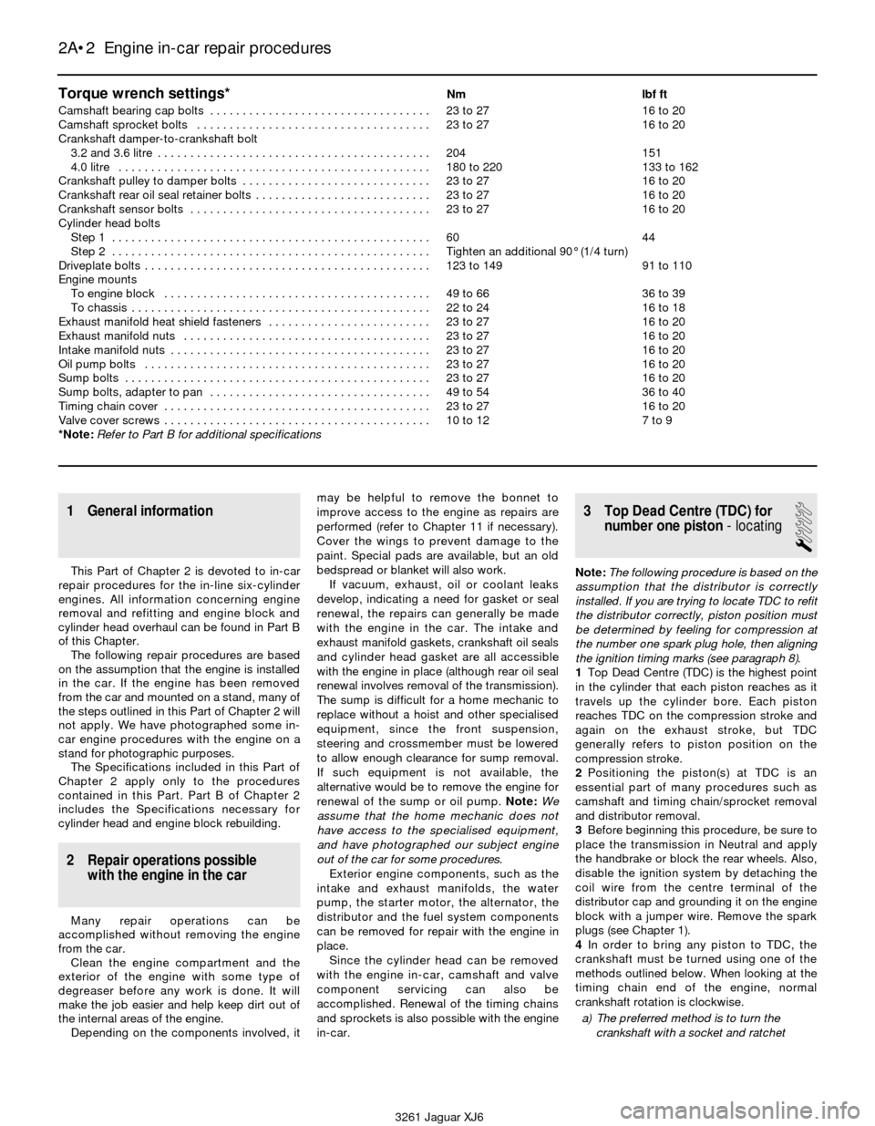
Torque wrench settings*Nm lbf ft
Camshaft bearing cap bolts . . . . . . . . . . . . . . . . . . . . . . . . . . . . . . . . . . 23 to 27 16 to 20
Camshaft sprocket bolts . . . . . . . . . . . . . . . . . . . . . . . . . . . . . . . . . . . . 23 to 27 16 to 20
Crankshaft damper-to-crankshaft bolt
3.2 and 3.6 litre . . . . . . . . . . . . . . . . . . . . . . . . . . . . . . . . . . . . . . . . . . 204 151
4.0 litre . . . . . . . . . . . . . . . . . . . . . . . . . . . . . . . . . . . . . . . . . . . . . . . . 180 to 220 133 to 162
Crankshaft pulley to damper bolts . . . . . . . . . . . . . . . . . . . . . . . . . . . . . 23 to 27 16 to 20
Crankshaft rear oil seal retainer bolts . . . . . . . . . . . . . . . . . . . . . . . . . . . 23 to 27 16 to 20
Crankshaft sensor bolts . . . . . . . . . . . . . . . . . . . . . . . . . . . . . . . . . . . . . 23 to 27 16 to 20
Cylinder head bolts
Step 1 . . . . . . . . . . . . . . . . . . . . . . . . . . . . . . . . . . . . . . . . . . . . . . . . . 60 44
Step 2 . . . . . . . . . . . . . . . . . . . . . . . . . . . . . . . . . . . . . . . . . . . . . . . . . Tighten an additional 90° (1/4 turn)
Driveplate bolts . . . . . . . . . . . . . . . . . . . . . . . . . . . . . . . . . . . . . . . . . . . . 123 to 149 91 to 110
Engine mounts
To engine block . . . . . . . . . . . . . . . . . . . . . . . . . . . . . . . . . . . . . . . . . 49 to 66 36 to 39
To chassis . . . . . . . . . . . . . . . . . . . . . . . . . . . . . . . . . . . . . . . . . . . . . . 22 to 24 16 to 18
Exhaust manifold heat shield fasteners . . . . . . . . . . . . . . . . . . . . . . . . . 23 to 27 16 to 20
Exhaust manifold nuts . . . . . . . . . . . . . . . . . . . . . . . . . . . . . . . . . . . . . . 23 to 27 16 to 20
Intake manifold nuts . . . . . . . . . . . . . . . . . . . . . . . . . . . . . . . . . . . . . . . . 23 to 27 16 to 20
Oil pump bolts . . . . . . . . . . . . . . . . . . . . . . . . . . . . . . . . . . . . . . . . . . . . 23 to 27 16 to 20
Sump bolts . . . . . . . . . . . . . . . . . . . . . . . . . . . . . . . . . . . . . . . . . . . . . . . 23 to 27 16 to 20
Sump bolts, adapter to pan . . . . . . . . . . . . . . . . . . . . . . . . . . . . . . . . . . 49 to 54 36 to 40
Timing chain cover . . . . . . . . . . . . . . . . . . . . . . . . . . . . . . . . . . . . . . . . . 23 to 27 16 to 20
Valve cover screws . . . . . . . . . . . . . . . . . . . . . . . . . . . . . . . . . . . . . . . . . 10 to 12 7 to 9
*Note:Refer to Part B for additional specifications
2A•2 Engine in-car repair procedures
3261 Jaguar XJ6
1 General information
This Part of Chapter 2 is devoted to in-car
repair procedures for the in-line six-cylinder
engines. All information concerning engine
removal and refitting and engine block and
cylinder head overhaul can be found in Part B
of this Chapter.
The following repair procedures are based
on the assumption that the engine is installed
in the car. If the engine has been removed
from the car and mounted on a stand, many of
the steps outlined in this Part of Chapter 2 will
not apply. We have photographed some in-
car engine procedures with the engine on a
stand for photographic purposes.
The Specifications included in this Part of
Chapter 2 apply only to the procedures
contained in this Part. Part B of Chapter 2
includes the Specifications necessary for
cylinder head and engine block rebuilding.
2 Repair operations possible
with the engine in the car
Many repair operations can be
accomplished without removing the engine
from the car.
Clean the engine compartment and the
exterior of the engine with some type of
degreaser before any work is done. It will
make the job easier and help keep dirt out of
the internal areas of the engine.
Depending on the components involved, itmay be helpful to remove the bonnet to
improve access to the engine as repairs are
performed (refer to Chapter 11 if necessary).
Cover the wings to prevent damage to the
paint. Special pads are available, but an old
bedspread or blanket will also work.
If vacuum, exhaust, oil or coolant leaks
develop, indicating a need for gasket or seal
renewal, the repairs can generally be made
with the engine in the car. The intake and
exhaust manifold gaskets, crankshaft oil seals
and cylinder head gasket are all accessible
with the engine in place (although rear oil seal
renewal involves removal of the transmission).
The sump is difficult for a home mechanic to
replace without a hoist and other specialised
equipment, since the front suspension,
steering and crossmember must be lowered
to allow enough clearance for sump removal.
If such equipment is not available, the
alternative would be to remove the engine for
renewal of the sump or oil pump. Note:We
assume that the home mechanic does not
have access to the specialised equipment,
and have photographed our subject engine
out of the car for some procedures.
Exterior engine components, such as the
intake and exhaust manifolds, the water
pump, the starter motor, the alternator, the
distributor and the fuel system components
can be removed for repair with the engine in
place.
Since the cylinder head can be removed
with the engine in-car, camshaft and valve
component servicing can also be
accomplished. Renewal of the timing chains
and sprockets is also possible with the engine
in-car.
3 Top Dead Centre (TDC) for
number one piston- locating
1
Note:The following procedure is based on the
assumption that the distributor is correctly
installed. If you are trying to locate TDC to refit
the distributor correctly, piston position must
be determined by feeling for compression at
the number one spark plug hole, then aligning
the ignition timing marks (see paragraph 8).
1Top Dead Centre (TDC) is the highest point
in the cylinder that each piston reaches as it
travels up the cylinder bore. Each piston
reaches TDC on the compression stroke and
again on the exhaust stroke, but TDC
generally refers to piston position on the
compression stroke.
2Positioning the piston(s) at TDC is an
essential part of many procedures such as
camshaft and timing chain/sprocket removal
and distributor removal.
3Before beginning this procedure, be sure to
place the transmission in Neutral and apply
the handbrake or block the rear wheels. Also,
disable the ignition system by detaching the
coil wire from the centre terminal of the
distributor cap and grounding it on the engine
block with a jumper wire. Remove the spark
plugs (see Chapter 1).
4In order to bring any piston to TDC, the
crankshaft must be turned using one of the
methods outlined below. When looking at the
timing chain end of the engine, normal
crankshaft rotation is clockwise.
a) The preferred method is to turn the
crankshaft with a socket and ratchet
Page 40 of 227
attached to the bolt threaded into the
front of the crankshaft. Apply pressure on
the bolt in a clockwise direction only.
Never turn the bolt anti-clockwise.
b) A remote starter switch, which may save
some time, can also be used. Follow the
instructions included with the switch.
Once the piston is close to TDC, use a
socket and ratchet as described in the
previous paragraph.
c) If an assistant is available to turn the
ignition switch to the Start position in
short bursts, you can get the piston close
to TDC without a remote starter switch.
Make sure your assistant is out of the car,
away from the ignition switch, then use a
socket and ratchet as described in
Paragraph a) to complete the procedure.
5Note the position of the terminal for the
number one spark plug lead on the distributor
cap. If the terminal isn’t marked, follow the
plug lead from the number one cylinder spark
plug to the cap.
6Use a felt-tip pen or chalk to make a mark
on the distributor body directly under the
number one terminal (see Chapter 5).
7Detach the cap from the distributor and set
it aside (see Chapter 1 if necessary).
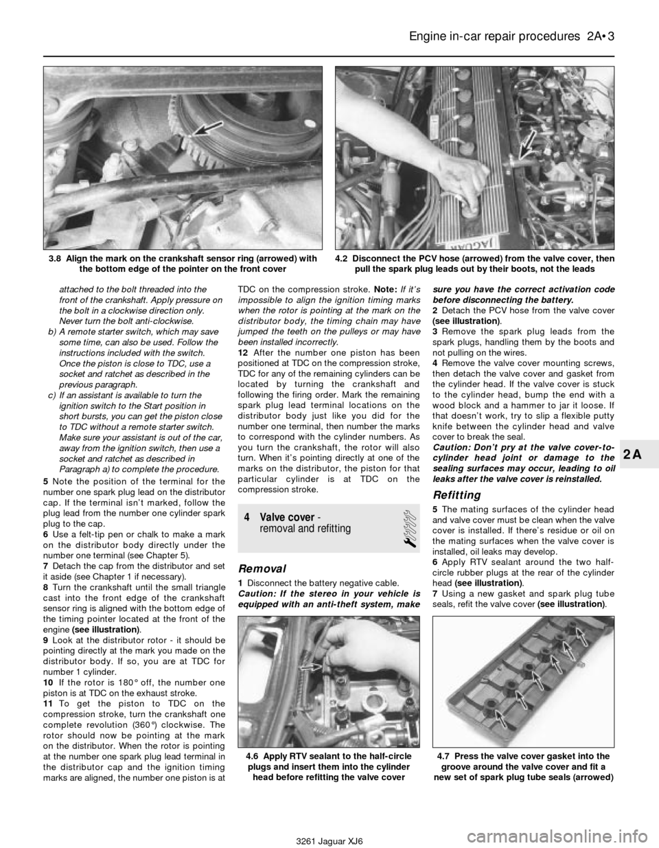
8Turn the crankshaft until the small triangle
cast into the front edge of the crankshaft
sensor ring is aligned with the bottom edge of
the timing pointer located at the front of the
engine(see illustration).
9Look at the distributor rotor - it should be
pointing directly at the mark you made on the
distributor body. If so, you are at TDC for
number 1 cylinder.
10If the rotor is 180° off, the number one
piston is at TDC on the exhaust stroke.
11To get the piston to TDC on the
compression stroke, turn the crankshaft one
complete revolution (360°) clockwise. The
rotor should now be pointing at the mark
on the distributor. When the rotor is pointing
at the number one spark plug lead terminal in
the distributor cap and the ignition timing
marks are aligned, the number one piston is atTDC on the compression stroke. Note:If it’s
impossible to align the ignition timing marks
when the rotor is pointing at the mark on the
distributor body, the timing chain may have
jumped the teeth on the pulleys or may have
been installed incorrectly.
12After the number one piston has been
positioned at TDC on the compression stroke,
TDC for any of the remaining cylinders can be
located by turning the crankshaft and
following the firing order. Mark the remaining
spark plug lead terminal locations on the
distributor body just like you did for the
number one terminal, then number the marks
to correspond with the cylinder numbers. As
you turn the crankshaft, the rotor will also
turn. When it’s pointing directly at one of the
marks on the distributor, the piston for that
particular cylinder is at TDC on the
compression stroke.
4 Valve cover-
removal and refitting
1
Removal
1Disconnect the battery negative cable.
Caution: If the stereo in your vehicle is
equipped with an anti-theft system, makesure you have the correct activation code
before disconnecting the battery.
2Detach the PCV hose from the valve cover
(see illustration).
3Remove the spark plug leads from the
spark plugs, handling them by the boots and
not pulling on the wires.
4Remove the valve cover mounting screws,
then detach the valve cover and gasket from
the cylinder head. If the valve cover is stuck
to the cylinder head, bump the end with a
wood block and a hammer to jar it loose. If
that doesn’t work, try to slip a flexible putty
knife between the cylinder head and valve
cover to break the seal.
Caution: Don’t pry at the valve cover-to-
cylinder head joint or damage to the
sealing surfaces may occur, leading to oil
leaks after the valve cover is reinstalled.
Refitting
5The mating surfaces of the cylinder head
and valve cover must be clean when the valve
cover is installed. If there’s residue or oil on
the mating surfaces when the valve cover is
installed, oil leaks may develop.
6Apply RTV sealant around the two half-
circle rubber plugs at the rear of the cylinder
head (see illustration).
7Using a new gasket and spark plug tube
seals, refit the valve cover (see illustration).
Engine in-car repair procedures 2A•3
2A
4.6 Apply RTV sealant to the half-circle
plugs and insert them into the cylinder
head before refitting the valve cover4.7 Press the valve cover gasket into the
groove around the valve cover and fit a
new set of spark plug tube seals (arrowed)
3261 Jaguar XJ6 3.8 Align the mark on the crankshaft sensor ring (arrowed) with
the bottom edge of the pointer on the front cover
4.2 Disconnect the PCV hose (arrowed) from the valve cover, then
pull the spark plug leads out by their boots, not the leads
Page 113 of 227
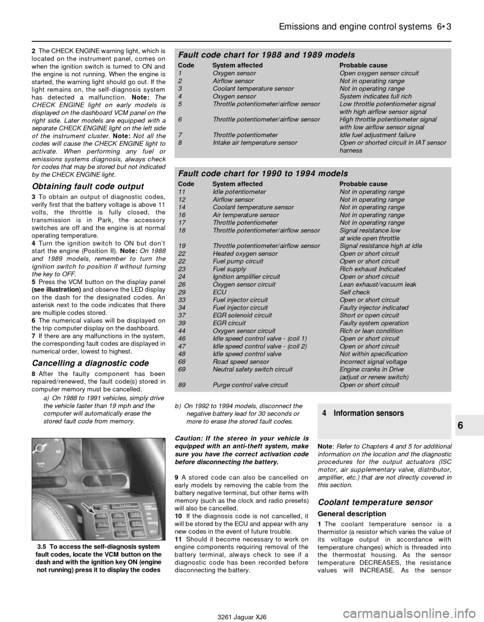
2The CHECK ENGINE warning light, which is
located on the instrument panel, comes on
when the ignition switch is turned to ON and
the engine is not running. When the engine is
started, the warning light should go out. If the
light remains on, the self-diagnosis system
has detected a malfunction. Note: The
CHECK ENGINE light on early models is
displayed on the dashboard VCM panel on the
right side. Later models are equipped with a
separate CHECK ENGINE light on the left side
of the instrument cluster.Note:Not all the
codes will cause the CHECK ENGINE light to
activate. When performing any fuel or
emissions systems diagnosis, always check
for codes that may be stored but not indicated
by the CHECK ENGINE light.
Obtaining fault code output
3To obtain an output of diagnostic codes,
verify first that the battery voltage is above 11
volts, the throttle is fully closed, the
transmission is in Park, the accessory
switches are off and the engine is at normal
operating temperature.
4Turn the ignition switch to ON but don’t
start the engine (Position II). Note:On 1988
and 1989 models, remember to turn the
ignition switch to position II without turning
the key to OFF.
5Press the VCM button on the display panel
(see illustration)and observe the LED display
on the dash for the designated codes. An
asterisk next to the code indicates that there
are multiple codes stored.
6The numerical values will be displayed on
the trip computer display on the dashboard.
7If there are any malfunctions in the system,
the corresponding fault codes are displayed in
numerical order, lowest to highest.
Cancelling a diagnostic code
8After the faulty component has been
repaired/renewed, the fault code(s) stored in
computer memory must be cancelled.
a) On 1988 to 1991 vehicles, simply drive
the vehicle faster than 19 mph and the
computer will automatically erase the
stored fault code from memory.b) On 1992 to 1994 models, disconnect the
negative battery lead for 30 seconds or
more to erase the stored fault codes.
Caution: If the stereo in your vehicle is
equipped with an anti-theft system, make
sure you have the correct activation code
before disconnecting the battery.
9A stored code can also be cancelled on
early models by removing the cable from the
battery negative terminal, but other items with
memory (such as the clock and radio presets)
will also be cancelled.
10If the diagnosis code is not cancelled, it
will be stored by the ECU and appear with any
new codes in the event of future trouble.
11Should it become necessary to work on
engine components requiring removal of the
battery terminal, always check to see if a
diagnostic code has been recorded before
disconnecting the battery.
4 Information sensors
Note: Refer to Chapters 4 and 5 for additional
information on the location and the diagnostic
procedures for the output actuators (ISC
motor, air supplementary valve, distributor,
amplifier, etc.) that are not directly covered in
this section.
Coolant temperature sensor
General description
1The coolant temperature sensor is a
thermistor (a resistor which varies the value of
its voltage output in accordance with
temperature changes) which is threaded into
the thermostat housing. As the sensor
temperature DECREASES, the resistance
values will INCREASE. As the sensor
Emissions and engine control systems 6•3
6
3.5 To access the self-diagnosis system
fault codes, locate the VCM button on the
dash and with the ignition key ON (engine
not running) press it to display the codes
3261 Jaguar XJ6
Fault code chart for 1988 and 1989 models
Code System affected Probable cause
1 Oxygen sensor Open oxygen sensor circuit
2 Airflow sensor Not in operating range
3 Coolant temperature sensor Not in operating range
4 Oxygen sensor System indicates full rich
5 Throttle potentiometer/airflow sensor Low throttle potentiometer signal
with high airflow sensor signal
6 Throttle potentiometer/airflow sensor High throttle potentiometer signal
with low airflow sensor signal
7 Throttle potentiometer Idle fuel adjustment failure
8 Intake air temperature sensor Open or shorted circuit in IAT sensor
harness
Fault code chart for 1990 to 1994 models
Code System affected Probable cause
11 Idle potentiometer Not in operating range
12 Airflow sensor Not in operating range
14 Coolant temperature sensor Not in operating range
16 Air temperature sensor Not in operating range
17 Throttle potentiometer Not in operating range
18 Throttle potentiometer/airflow sensor Signal resistance low
at wide open throttle
19 Throttle potentiometer/airflow sensor Signal resistance high at idle
22 Heated oxygen sensor Open or short circuit
22 Fuel pump circuit Open or short circuit
23 Fuel supply Rich exhaust Indicated
24 Ignition amplifier circuit Open or short circuit
26 Oxygen sensor circuit Lean exhaust/vacuum leak
29 ECU Self check
33 Fuel injector circuit Open or short circuit
34 Fuel injector circuit Faulty injector indicated
37 EGR solenoid circuit Short or open circuit
39 EGR circuit Faulty system operation
44 Oxygen sensor circuit Rich or lean condition
46 Idle speed control valve - (coil 1) Open or short circuit
47 Idle speed control valve - (coil 2) Open or short circuit
48 Idle speed control valve Not within specification
68 Road speed sensor Incorrect signal voltage
69 Neutral safety switch circuit Engine cranks in Drive
(adjust or renew switch)
89 Purge control valve circuit Open or short circuit
Page 172 of 227
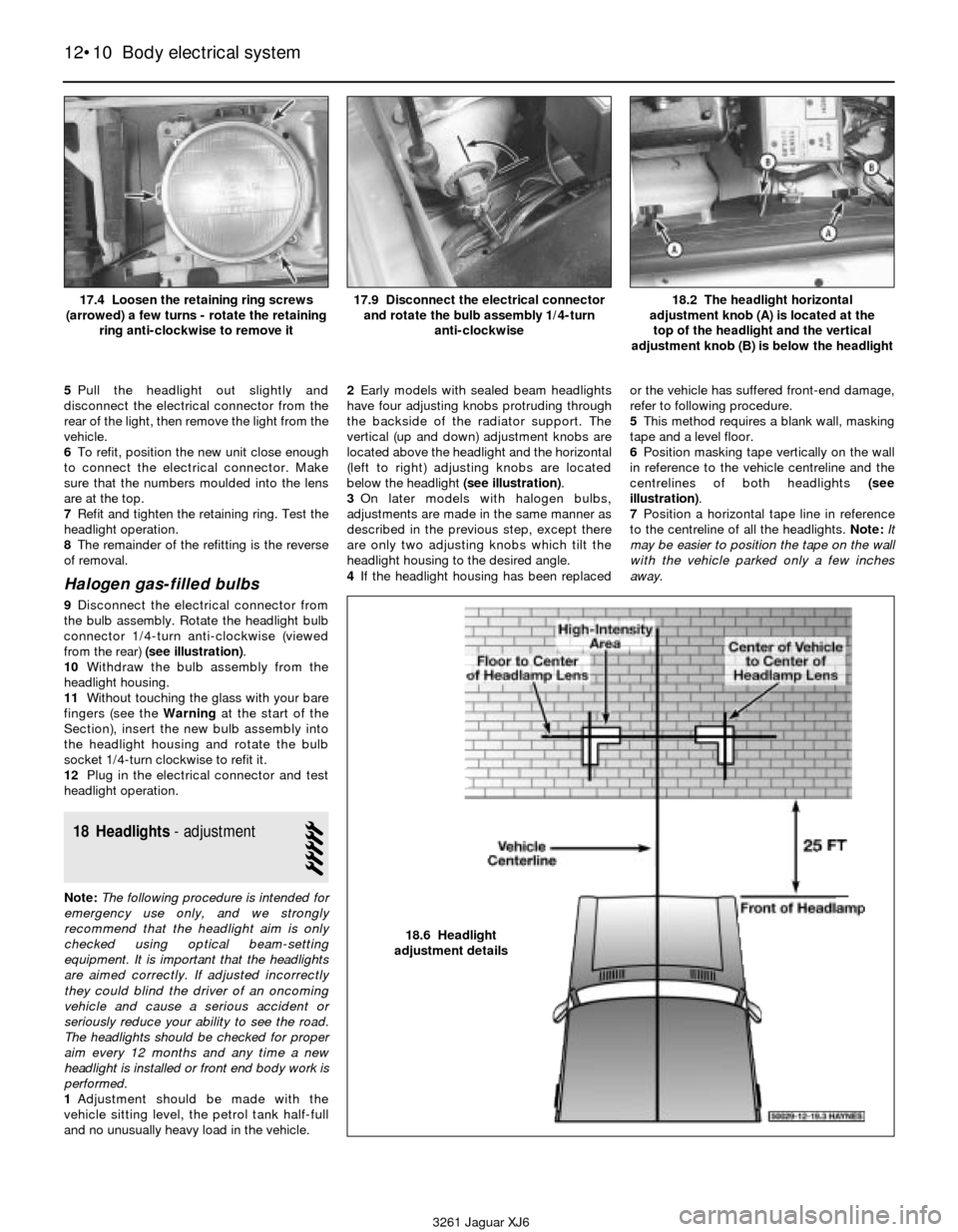
5Pull the headlight out slightly and
disconnect the electrical connector from the
rear of the light, then remove the light from the
vehicle.
6To refit, position the new unit close enough
to connect the electrical connector. Make
sure that the numbers moulded into the lens
are at the top.
7Refit and tighten the retaining ring. Test the
headlight operation.
8The remainder of the refitting is the reverse
of removal.
Halogen gas-filled bulbs
9Disconnect the electrical connector from
the bulb assembly. Rotate the headlight bulb
connector 1/4-turn anti-clockwise (viewed
from the rear) (see illustration).
10Withdraw the bulb assembly from the
headlight housing.
11Without touching the glass with your bare
fingers (see the Warningat the start of the
Section), insert the new bulb assembly into
the headlight housing and rotate the bulb
socket 1/4-turn clockwise to refit it.
12Plug in the electrical connector and test
headlight operation.
18 Headlights- adjustment
5
Note:The following procedure is intended for
emergency use only, and we strongly
recommend that the headlight aim is only
checked using optical beam-setting
equipment. It is important that the headlights
are aimed correctly. If adjusted incorrectly
they could blind the driver of an oncoming
vehicle and cause a serious accident or
seriously reduce your ability to see the road.
The headlights should be checked for proper
aim every 12 months and any time a new
headlight is installed or front end body work is
performed.
1Adjustment should be made with the
vehicle sitting level, the petrol tank half-full
and no unusually heavy load in the vehicle.2Early models with sealed beam headlights
have four adjusting knobs protruding through
the backside of the radiator support. The
vertical (up and down) adjustment knobs are
located above the headlight and the horizontal
(left to right) adjusting knobs are located
below the headlight (see illustration).
3On later models with halogen bulbs,
adjustments are made in the same manner as
described in the previous step, except there
are only two adjusting knobs which tilt the
headlight housing to the desired angle.
4If the headlight housing has been replacedor the vehicle has suffered front-end damage,
refer to following procedure.
5This method requires a blank wall, masking
tape and a level floor.
6Position masking tape vertically on the wall
in reference to the vehicle centreline and the
centrelines of both headlights (see
illustration).
7Position a horizontal tape line in reference
to the centreline of all the headlights. Note:It
may be easier to position the tape on the wall
with the vehicle parked only a few inches
away.
12•10 Body electrical system
3261 Jaguar XJ618.2 The headlight horizontal
adjustment knob (A) is located at the
top of the headlight and the vertical
adjustment knob (B) is below the headlight
17.4 Loosen the retaining ring screws
(arrowed) a few turns - rotate the retaining
ring anti-clockwise to remove it17.9 Disconnect the electrical connector
and rotate the bulb assembly 1/4-turn
anti-clockwise
18.6 Headlight
adjustment details
Page 174 of 227
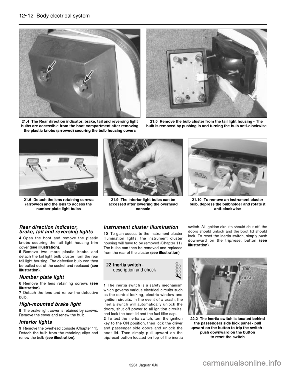
Rear direction indicator,
brake, tail and reversing lights
4Open the boot and remove the plastic
knobs securing the tail light housing trim
cover (see illustration).
5Remove two more plastic knobs and
detach the tail light bulb cluster from the rear
tail light housing. The defective bulb can then
be pulled out of the socket and replaced (see
illustration).
Number plate light
6Remove the lens retaining screws (see
illustration).
7Detach the lens and renew the defective
bulb.
High-mounted brake light
8The brake light cover is retained by screws.
Remove the cover and renew the bulb.
Interior lights
9Remove the overhead console (Chapter 11).
Detach the bulb from the retaining clips and
renew the bulb (see illustration).
Instrument cluster illumination
10To gain access to the instrument cluster
illumination lights, the instrument cluster
housing will have to be removed (Chapter 11).
The bulbs can then be removed and replaced
from the rear of the cluster (see illustration).
22 Inertia switch-
description and check
1
1The inertia switch is a safety mechanism
which governs various electrical circuits such
as the central locking, electric window and
ignition circuits. In the event of a crash, the
inertia switch will automatically unlock the
doors, shut off power to all ignition circuits,
and lock the boot lid and the fuel filler cap.
2To test the inertia switch, turn the ignition
key to the ON position, then lock the driver
and passenger side doors and unlock the
boot lid. Then simply pull upward on the
trip/reset button located on top of the inertiaswitch. All ignition circuits should shut off, the
doors should unlock and the boot lid should
lock. To reset the inertia switch, simply push
downward on the trip/reset button (see
illustration).
12•12 Body electrical system
21.6 Detach the lens retaining screws
(arrowed) and the lens to access the
number plate light bulbs21.9 The interior light bulbs can be
accessed after lowering the overhead
console21.10 To remove an instrument cluster
bulb, depress the bulbholder and rotate it
anti-clockwise
3261 Jaguar XJ6 21.4 The Rear direction indicator, brake, tail and reversing light
bulbs are accessible from the boot compartment after removing
the plastic knobs (arrowed) securing the bulb housing covers
21.5 Remove the bulb cluster from the tail light housing - The
bulb is removed by pushing in and turning the bulb anti-clockwise
22.2 The inertia switch is located behind
the passengers side kick panel - pull
upward on the button to trip the switch -
push downward on the button
to reset the switch
Page 204 of 227

3261 Jaguar XJ6
Use of EnglishREF•3
As the main part of this book has been written in the US, it uses the appropriate US component names, phrases, and spelling. Some of these
differ from those used in the UK. Normally, these cause no difficulty, but to make sure, a glossary is printed below. When ordering spare parts,
remember the parts list may use some of these words:
AMERICAN ENGLISH
Aluminum Aluminium
Antenna Aerial
Authorized Authorised
Auto parts stores Motor factors
Axleshaft Halfshaft
Back-up Reverse
Barrel Choke/venturi
Block Chock
Box-end wrench Ring spanner
Bushing Bush
Carburetor Carburettor
Center Centre
Coast Freewheel
Color Colour
Convertible Drop head coupe
Cotter pin Split pin
Counterclockwise Anti-clockwise
Countershaft (of gearbox) Layshaft
Dashboard Facia
Denatured alcohol Methylated spirit
Dome lamp Interior light
Driveaxle Driveshaft
Driveshaft Propeller shaft
Fender Wing/mudguard
Firewall Bulkhead
Flashlight Torch
Float bowl Float chamber
Floor jack Trolley jack
Freeway, turnpike etc Motorway
Freeze plug Core plug
Frozen Seized
Gas tank Petrol tank
Gasoline (gas) Petrol
Gearshift Gearchange
Generator (DC) Dynamo
Ground (electrical) Earth
Header Exhaust manifold
Heat riser Hot spot
High Top gear
Hood (engine cover) Bonnet
Installation Refitting
Intake Inlet
Jackstands Axle stands
Jumper cable Jump lead
Keeper Collet
Kerosene Paraffin
Knock pin Roll pin
Lash Clearance
Lash Free-play
Latch Catch
Latches Locks
License plate Number plate
Light Lamp
Lock (for valve spring retainer) Split cotter (for valve spring cap)
Lopes Hunts
Lug nut/bolt Wheel nut/bolt
Metal chips or debris Swarf
Misses Misfires
AMERICAN ENGLISH
Muffler Silencer
Odor Odour
Oil pan Sump
Open flame Naked flame
Panel wagon/van Van
Parking brake Handbrake
Parking light Sidelight
Pinging Pinking
Piston pin or wrist pin Gudgeon pin
Piston pin or wrist pin Small end, little end
Pitman arm Drop arm
Power brake booster Servo unit
Primary shoe (of brake) Leading shoe (of brake)
Prussian blue Engineer’s blue
Pry Prise (force apart)
Prybar Lever
Prying Levering
Quarter window Quarterlight
Recap Retread
Release cylinder Slave cylinder
Repair shop Garage
Replacement Renewal
Ring gear (of differential) Crownwheel
Rocker panel (beneath doors) Sill panel (beneath doors)
Rod bearing Big-end bearing
Rotor/disk Disc (brake)
Secondary shoe (of brake) Trailing shoe (of brake)
Sedan Saloon
Setscrew, Allen screw Grub screw
Shock absorber, shock Damper
Snap-ring Circlip
Soft top Hood
Spacer Distance piece
Spare tire Spare wheel
Spark plug wires HT leads
Spindle arm Steering arm
Stabilizer or sway bar Anti-roll bar
Station wagon Estate car
Stumbles Hesitates
Tang or lock Tab washer
Throw-out bearing Thrust bearing
Tie-rod or connecting rod (of steering) Trackrod
Tire Tyre
Transmission Gearbox
Troubleshooting Fault finding/diagnosis
Trunk Boot (luggage compartment)
Turn signal Indicator
TV (throttle valve) cable Kickdown cable
Unpublicized Unpublicised
Valve cover Rocker cover
Valve lifter Tappet
Valve lifter or tappet Cam follower or tappet
Vapor Vapour
Vise Vice
Wheel cover Roadwheel trim
Whole drive line Transmission
Windshield Windscreen
Wrench Spanner