Speed sensor JEEP CHEROKEE 1994 Service Owner's Manual
[x] Cancel search | Manufacturer: JEEP, Model Year: 1994, Model line: CHEROKEE, Model: JEEP CHEROKEE 1994Pages: 1784, PDF Size: 77.09 MB
Page 137 of 1784
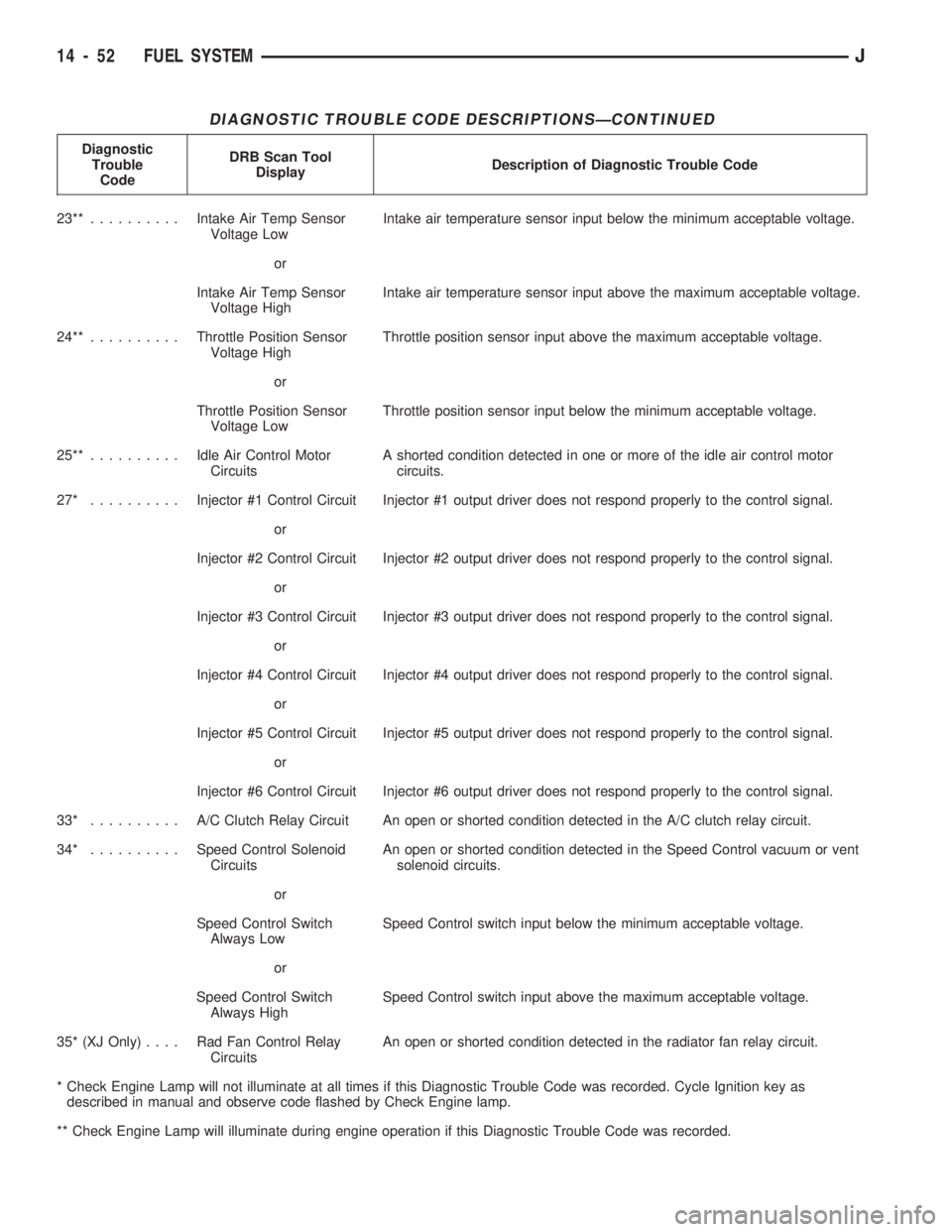
DIAGNOSTIC TROUBLE CODE DESCRIPTIONSÐCONTINUED
Diagnostic
Trouble
CodeDRB Scan Tool
DisplayDescription of Diagnostic Trouble Code
23**..........Intake Air Temp Sensor
Voltage LowIntake air temperature sensor input below the minimum acceptable voltage.
or
Intake Air Temp Sensor
Voltage HighIntake air temperature sensor input above the maximum acceptable voltage.
24**..........Throttle Position Sensor
Voltage HighThrottle position sensor input above the maximum acceptable voltage.
or
Throttle Position Sensor
Voltage LowThrottle position sensor input below the minimum acceptable voltage.
25**..........Idle Air Control Motor
CircuitsA shorted condition detected in one or more of the idle air control motor
circuits.
27* ..........Injector #1 Control Circuit Injector #1 output driver does not respond properly to the control signal.
or
Injector #2 Control Circuit Injector #2 output driver does not respond properly to the control signal.
or
Injector #3 Control Circuit Injector #3 output driver does not respond properly to the control signal.
or
Injector #4 Control Circuit Injector #4 output driver does not respond properly to the control signal.
or
Injector #5 Control Circuit Injector #5 output driver does not respond properly to the control signal.
or
Injector #6 Control Circuit Injector #6 output driver does not respond properly to the control signal.
33* .......... A/CClutch Relay Circuit An open or shorted condition detected in the A/C clutch relay circuit.
34* ..........Speed Control Solenoid
CircuitsAn open or shorted condition detected in the Speed Control vacuum or vent
solenoid circuits.
or
Speed Control Switch
Always LowSpeed Control switch input below the minimum acceptable voltage.
or
Speed Control Switch
Always HighSpeed Control switch input above the maximum acceptable voltage.
35* (XJ Only).... RadFanControl Relay
CircuitsAn open or shorted condition detected in the radiator fan relay circuit.
* Check Engine Lamp will not illuminate at all times if this Diagnostic Trouble Code was recorded. Cycle Ignition key as
described in manual and observe code flashed by Check Engine lamp.
** Check Engine Lamp will illuminate during engine operation if this Diagnostic Trouble Code was recorded.
14 - 52 FUEL SYSTEMJ
Page 139 of 1784
MULTI-PORT FUEL INJECTION (MFI)ÐCOMPONENT REMOVAL/INSTALLATION
INDEX
page page
Accelerator Pedal and Throttle Cable......... 54
Air Cleaner Housing...................... 54
Air Conditioning (A/C) Clutch Relay........... 54
Air Filter............................... 54
Automatic Shut Down (ASD) Relay........... 54
Brake Switch............................ 54
Camshaft Position Sensor.................. 54
Crankshaft Position Sensor................. 55
Engine Coolant Temperature Sensor.......... 55
Fuel Filter.............................. 55
Fuel Injector............................ 55
Fuel Pump Module....................... 56
Fuel Pump Relay........................ 56
Fuel Rail Assembly....................... 56
Fuel System Pressure Release Procedure...... 56
Fuel Tank Pressure Relief/Rollover Valve...... 56
Fuel Tanks............................. 56Fuel Tubes/Lines/Hoses and Clamps.......... 56
Idle Air Control (IAC) Motor................. 56
Ignition Coil............................. 57
Intake Air Temperature Sensor.............. 54
Intake Manifold.......................... 57
Manifold Absolute Pressure (MAP) Sensor..... 57
Oxygen (O2S) Sensor..................... 57
Park Neutral Switch....................... 58
Power Steering Pressure SwitchÐ2.5L
Engine Only........................... 58
Powertrain Control Module (PCM)............ 58
Quick-Connect Fittings..................... 59
Throttle Body............................ 59
Throttle Position Sensor (TPS).............. 59
Torque Converter Clutch Relay.............. 60
Vehicle Speed Sensor..................... 60
ACCELERATOR PEDAL AND THROTTLE CABLE
Refer to the Accelerator Pedal and Throttle Cable
section of this group for removal/installation proce-
dures.
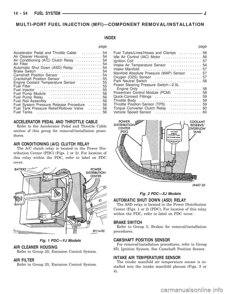
AIR CONDITIONING (A/C) CLUTCH RELAY
The A/C clutch relay is located in the Power Dis-
tribution Center (PDC) (Figs. 1 or 2). For location of
this relay within the PDC, refer to label on PDC
cover.
AIR CLEANER HOUSING
Refer to Group 25, Emission Control System.
AIR FILTER
Refer to Group 25, Emission Control System.
AUTOMATIC SHUT DOWN (ASD) RELAY
The ASD relay is located in the Power Distribution
Center (Figs. 1 or 2) (PDC). For location of this relay
within the PDC, refer to label on PDC cover.
BRAKE SWITCH
Refer to Group 5, Brakes for removal/installation
procedures.
CAMSHAFT POSITION SENSOR
For removal/installation procedures, refer to Group
8D, Ignition System. See Camshaft Position Sensor.
INTAKE AIR TEMPERATURE SENSOR
The intake manifold air temperature sensor is in-
stalled into the intake manifold plenum (Figs. 3 or
4).
Fig. 1 PDCÐYJ Models
Fig. 2 PDCÐXJ Models
14 - 54 FUEL SYSTEMJ
Page 144 of 1784
INSTALLATION
(1) After the PCM electrical connector has been
separated from the PCM, inspect the pins for corro-
sion, being spread apart, bent or misaligned. Also in-
spect the pin heights in the connector. If the pin
heights are different, this would indicate a pin has
separated from the connector. Repair as necessary.
(2) Install PCM. Tighten three mounting bolts to 1
Nzm (9 in. lbs.) torque.
(3) Engage 60-way connector into PCM. Tighten
connector mounting bolt to 4 Nzm (35 in. lbs.) torque.
(4) YJ Models: Install windshield washer fluid
tank.
(5) Connect negative cable to battery.
QUICK-CONNECT FITTINGS
Refer to the Fuel Delivery System section of this
group for removal/installation procedures.
THROTTLE BODY
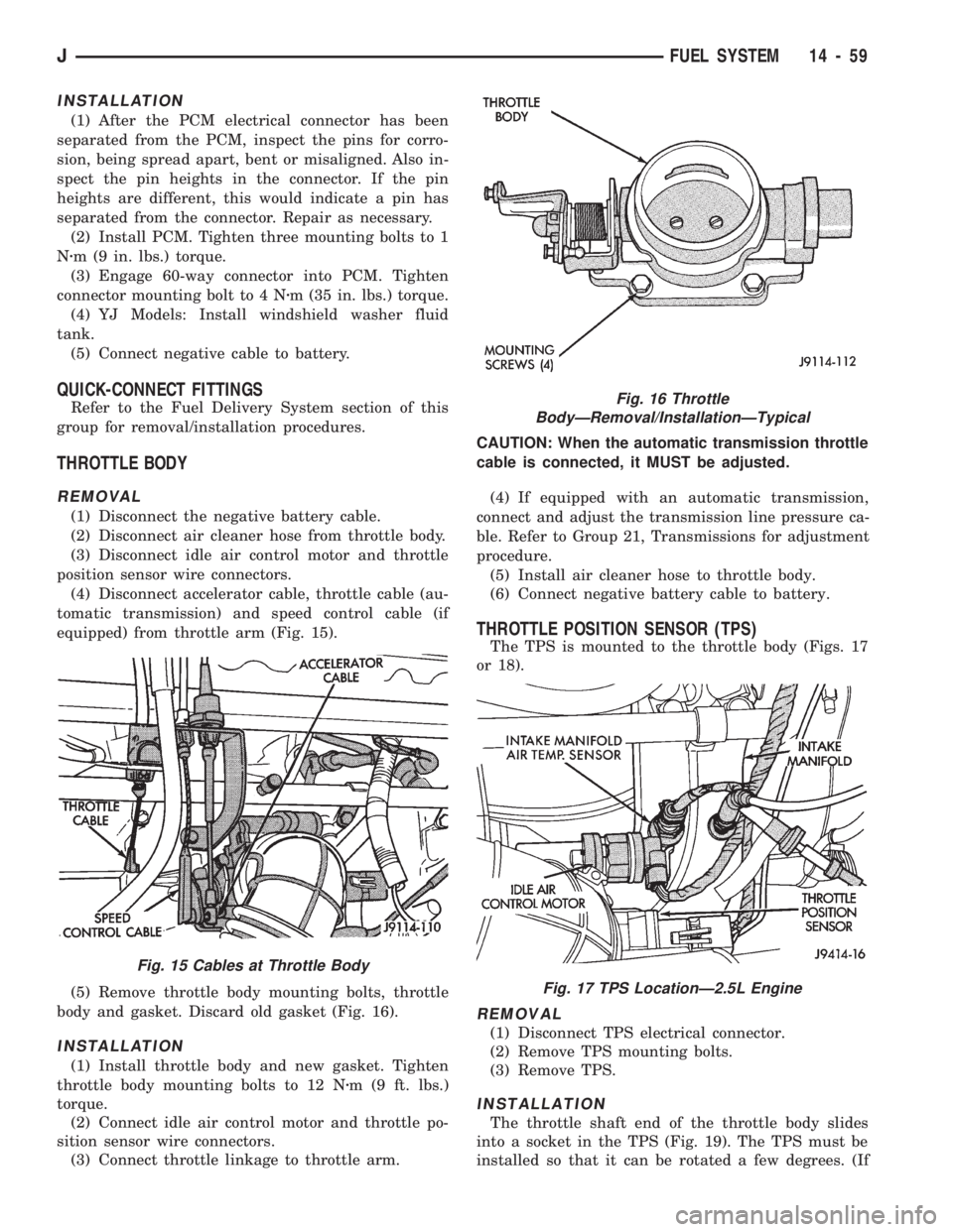
REMOVAL
(1) Disconnect the negative battery cable.
(2) Disconnect air cleaner hose from throttle body.
(3) Disconnect idle air control motor and throttle
position sensor wire connectors.
(4) Disconnect accelerator cable, throttle cable (au-
tomatic transmission) and speed control cable (if
equipped) from throttle arm (Fig. 15).
(5) Remove throttle body mounting bolts, throttle
body and gasket. Discard old gasket (Fig. 16).
INSTALLATION
(1) Install throttle body and new gasket. Tighten
throttle body mounting bolts to 12 Nzm (9 ft. lbs.)
torque.
(2) Connect idle air control motor and throttle po-
sition sensor wire connectors.
(3) Connect throttle linkage to throttle arm.CAUTION: When the automatic transmission throttle
cable is connected, it MUST be adjusted.
(4) If equipped with an automatic transmission,
connect and adjust the transmission line pressure ca-
ble. Refer to Group 21, Transmissions for adjustment
procedure.
(5) Install air cleaner hose to throttle body.
(6) Connect negative battery cable to battery.
THROTTLE POSITION SENSOR (TPS)
The TPS is mounted to the throttle body (Figs. 17
or 18).
REMOVAL
(1) Disconnect TPS electrical connector.
(2) Remove TPS mounting bolts.
(3) Remove TPS.
INSTALLATION
The throttle shaft end of the throttle body slides
into a socket in the TPS (Fig. 19). The TPS must be
installed so that it can be rotated a few degrees. (If
Fig. 16 Throttle
BodyÐRemoval/InstallationÐTypical
Fig. 17 TPS LocationÐ2.5L Engine
Fig. 15 Cables at Throttle Body
JFUEL SYSTEM 14 - 59
Page 145 of 1784
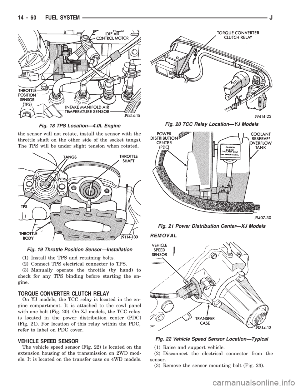
the sensor will not rotate, install the sensor with the
throttle shaft on the other side of the socket tangs).
The TPS will be under slight tension when rotated.
(1) Install the TPS and retaining bolts.
(2) Connect TPS electrical connector to TPS.
(3) Manually operate the throttle (by hand) to
check for any TPS binding before starting the en-
gine.
TORQUE CONVERTER CLUTCH RELAY
On YJ models, the TCC relay is located in the en-
gine compartment. It is attached to the cowl panel
with one bolt (Fig. 20). On XJ models, the TCC relay
is located in the power distribution center (PDC)
(Fig. 21). For location of this relay within the PDC,
refer to label on PDC cover.
VEHICLE SPEED SENSOR
The vehicle speed sensor (Fig. 22) is located on the
extension housing of the transmission on 2WD mod-
els. It is located on the transfer case on 4WD models.
REMOVAL
(1) Raise and support vehicle.
(2) Disconnect the electrical connector from the
sensor.
(3) Remove the sensor mounting bolt (Fig. 23).
Fig. 18 TPS LocationÐ4.0L Engine
Fig. 19 Throttle Position SensorÐInstallation
Fig. 20 TCC Relay LocationÐYJ Models
Fig. 21 Power Distribution CenterÐXJ Models
Fig. 22 Vehicle Speed Sensor LocationÐTypical
14 - 60 FUEL SYSTEMJ
Page 146 of 1784
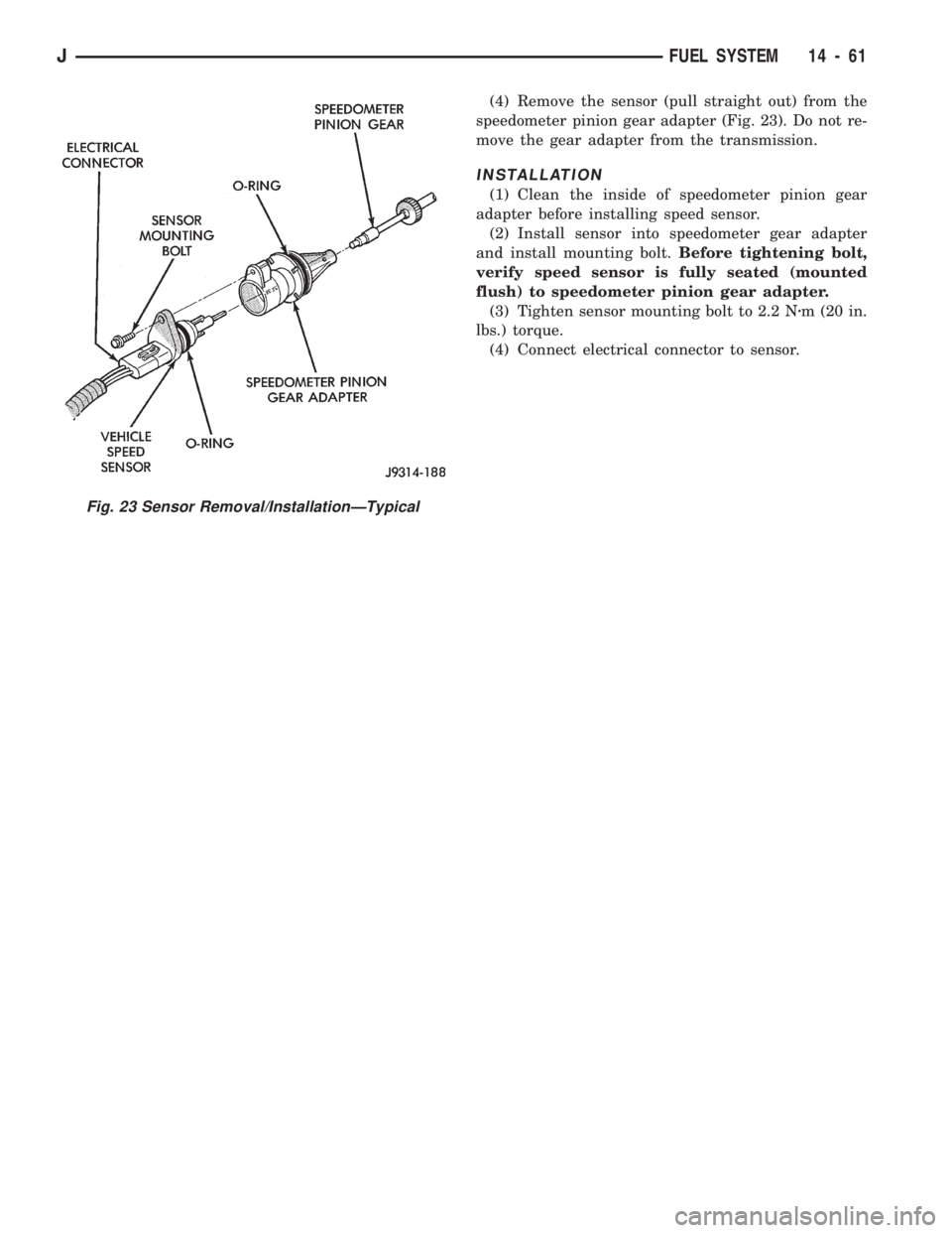
(4) Remove the sensor (pull straight out) from the
speedometer pinion gear adapter (Fig. 23). Do not re-
move the gear adapter from the transmission.
INSTALLATION
(1) Clean the inside of speedometer pinion gear
adapter before installing speed sensor.
(2) Install sensor into speedometer gear adapter
and install mounting bolt.Before tightening bolt,
verify speed sensor is fully seated (mounted
flush) to speedometer pinion gear adapter.
(3) Tighten sensor mounting bolt to 2.2 Nzm (20 in.
lbs.) torque.
(4) Connect electrical connector to sensor.
Fig. 23 Sensor Removal/InstallationÐTypical
JFUEL SYSTEM 14 - 61
Page 150 of 1784
ABS BRAKE DIAGNOSIS
INDEX
page page
ABS Fault Diagnosis....................... 4
ABS System Wiring and Electrical Circuits...... 4
ABS Warning Light Display.................. 3
Brake Warning Light Display................. 4
Diagnosis Procedures...................... 3
ECU Diagnosis........................... 4
HCU Diagnosis........................... 4Loss of Sensor Input....................... 3
Operating Sound Levels.................... 3
Rear Speed Sensor Air Gap................. 3
Steering Response........................ 3
Vehicle Response in Antilock Mode............ 3
Wheel/Tire Size and Input Signals............. 3
DIAGNOSIS PROCEDURES
ABS diagnosis involves three basic steps. First is
observation of the warning light display. Second is a
visual examination for low fluid level, leaks, parking
brakes applied, or obvious damage to system compo-
nents or wires. The third step involves using the
DRB II scan tool to identify a faulty component.
The visual examination requires a check of reser-
voir fluid level and all system components. Things to
look for are leaks, loose connections, or obvious com-
ponent damage.
The final diagnosis step involves using the DRB II
scan tool to determine the specific circuit or compo-
nent at fault. The tester is connected to the ABS di-
agnostic connector in the passenger compartment.
The connector is at the driver side of the center con-
sole under the instrument panel. Refer to the DRB II
scan tool Manual for tester procedures. Also refer to
the ABS Fault Diagnosis charts at the end of this
section for additional diagnosis information.
Initial faults should be cleared and the vehicle road
tested to reset any faults that remain in the system.
Faults can be cleared with the DRB II scan tool.
REAR SPEED SENSOR AIR GAP
The front wheel sensors are fixed and cannot be ad-
justed. Only the rear sensor air gap is adjustable. Air
gap must be set with a brass feeler gauge.
Correct air gap is important to proper signal gen-
eration. An air gap that is too large may cause com-
plete loss of sensor input. Or, a gap that is too small
could produce a false input signal, or damaging con-
tact between the sensor and tone ring.
WHEEL/TIRE SIZE AND INPUT SIGNALS
Antilock system operation is dependant on accurate
signals from the wheel speed sensors. Ideally, the ve-
hicle wheels and tires should all be the same size
and type. However, the Jeep ABS system is designed
to function with a compact spare tire installed.
OPERATING SOUND LEVELS
The ABS pump and solenoid valves may produce
some sound as they cycle on and off. This is a normal
condition and should not be mistaken for faulty oper-
ation.
VEHICLE RESPONSE IN ANTILOCK MODE
During antilock braking, the HCU solenoid valves
cycle rapidly in response to ECU inputs.
The driver will experience a pulsing sensation
within the vehicle as the solenoids decrease, hold, or
increase pressure as needed. A pulsing brake pedal
will also be noted.
The pulsing sensation occurs as the solenoids cycle
during antilock mode braking. A slight pulse in the
brake pedal may also be noted during the dynamic
self check part of system initialization.
STEERING RESPONSE
A modest amount of steering input is required dur-
ing extremely high deceleration braking, or when
braking on differing traction surfaces. An example of
differing traction surfaces would be when the left
side wheels are on ice and the right side wheels are
on dry pavement.
LOSS OF SENSOR INPUT
Sensor malfunctions will most likely be due to
loose connections, damaged sensor wires, incorrect
rear sensor air gap, or a malfunctioning sensor. Ad-
ditional causes of sensor faults would be sensor and
tone ring misalignment or damage.
ABS WARNING LIGHT DISPLAY
ABS Light Illuminates At Startup
The amber ABS light illuminates at startup as
part of the system self check feature. The light illu-
minates for 2-3 seconds then goes off as part of the
normal self check routine.
ABS Light Remains On After Startup
An ABS system fault is indicated when the light
remains on after startup. Diagnosis with the DRB II
JBRAKES 5 - 3
Page 151 of 1784
scan tool will be necessary to determine which ABS
component has malfunctioned.
ABS Light Illuminates During Brake Stop
A system fault such as loss of speed sensor signal
or solenoid failure, will cause the amber warning
light to illuminate. The most effective procedure here
is to check for obvious damage first. Then check the
electronic components with the DRB II scan tool.
BRAKE WARNING LIGHT DISPLAY
The red brake warning light and the ABS light op-
erate independently. If the red light remains on after
startup or illuminates during a brake stop, refer to
the standard brake system diagnosis section. Either
the parking brakes are applied, or a wheel brake
malfunction has occurred.
ECU DIAGNOSIS
The ECU controls all phases of antilock system op-
eration. It also differentiates between normal and an-
tilock mode braking.
The ECU monitors and processes the signals gen-
erated from all of the system sensors at all times.
The ECU program includes a self check routine
that tests each of the system components. The self
check occurs during both phases of the initialization
program. A failure of the self check program will
cause the immediate illumination of the amber warn-
ing light. The light will also illuminate if a solenoid
or other system component fails during the dynamic
phase of initialization.
If a system malfunction should occur, do not imme-
diately replace the ECU. A blown system fuse, bad
chassis ground, or loss of feed voltage will each cause
a system malfunction similar to an ECU failure.
Never replace the ECU unless diagnosis with the
DRB II scan tool indicates this is necessary.
HCU DIAGNOSIS
The HCU pump and motor and solenoid valve body
are serviced only as an assembly. The HCU assembly
should not be replaced unless a fault has actually
been confirmed. Verify fault conditions with the DRB
II scan tool before proceeding with repair.
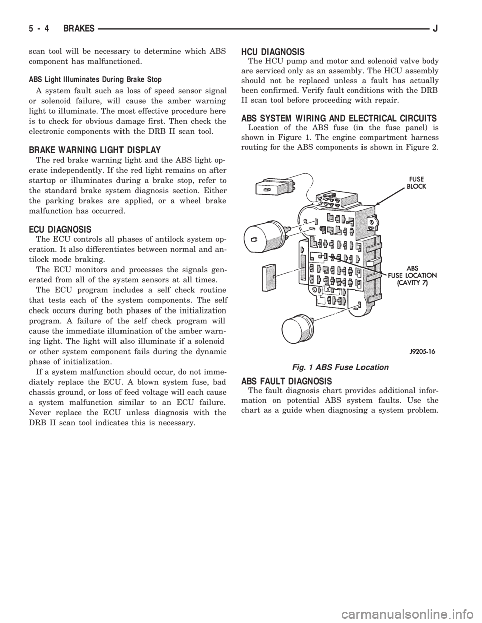
ABS SYSTEM WIRING AND ELECTRICAL CIRCUITS
Location of the ABS fuse (in the fuse panel) is
shown in Figure 1. The engine compartment harness
routing for the ABS components is shown in Figure 2.
ABS FAULT DIAGNOSIS
The fault diagnosis chart provides additional infor-
mation on potential ABS system faults. Use the
chart as a guide when diagnosing a system problem.
Fig. 1 ABS Fuse Location
5 - 4 BRAKESJ
Page 186 of 1784
ABS SYSTEM OPERATION
INDEX
page page
Acceleration Switch....................... 41
Combination Valve....................... 42
Electronic Control Unit (ECU)............... 41
General Information....................... 39
Hydraulic Control Unit (HCU)................ 39
Ignition Switch........................... 42Master Cylinder.......................... 40
Pedal Travel Sensor...................... 41
Power Brake Booster..................... 40
System Relays.......................... 42
System Warning Lights.................... 42
Wheel Speed Sensors..................... 41
GENERAL INFORMATION
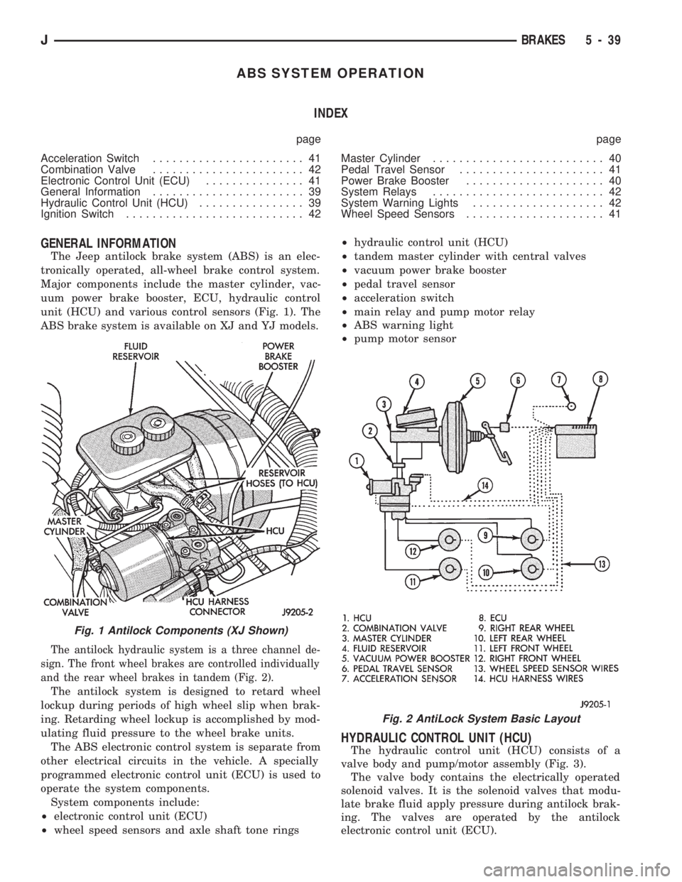
The Jeep antilock brake system (ABS) is an elec-
tronically operated, all-wheel brake control system.
Major components include the master cylinder, vac-
uum power brake booster, ECU, hydraulic control
unit (HCU) and various control sensors (Fig. 1). The
ABS brake system is available on XJ and YJ models.
The antilock hydraulic system is a three channel de-
sign. The front wheel brakes are controlled individually
and the rear wheel brakes in tandem (Fig. 2).
The antilock system is designed to retard wheel
lockup during periods of high wheel slip when brak-
ing. Retarding wheel lockup is accomplished by mod-
ulating fluid pressure to the wheel brake units.
The ABS electronic control system is separate from
other electrical circuits in the vehicle. A specially
programmed electronic control unit (ECU) is used to
operate the system components.
System components include:
²electronic control unit (ECU)
²wheel speed sensors and axle shaft tone rings²hydraulic control unit (HCU)
²tandem master cylinder with central valves
²vacuum power brake booster
²pedal travel sensor
²acceleration switch
²main relay and pump motor relay
²ABS warning light
²pump motor sensor
HYDRAULIC CONTROL UNIT (HCU)
The hydraulic control unit (HCU) consists of a
valve body and pump/motor assembly (Fig. 3).
The valve body contains the electrically operated
solenoid valves. It is the solenoid valves that modu-
late brake fluid apply pressure during antilock brak-
ing. The valves are operated by the antilock
electronic control unit (ECU).
Fig. 1 Antilock Components (XJ Shown)
Fig. 2 AntiLock System Basic Layout
JBRAKES 5 - 39
Page 188 of 1784
4). The engine intake manifold serves as the vacuum
source for booster operation.
The booster is mounted on the engine compartment
side of the dash panel. The master cylinder is
mounted on attaching studs at the front of the
booster. The master cylinder central valves are di-
rectly actuated by the booster push rod.
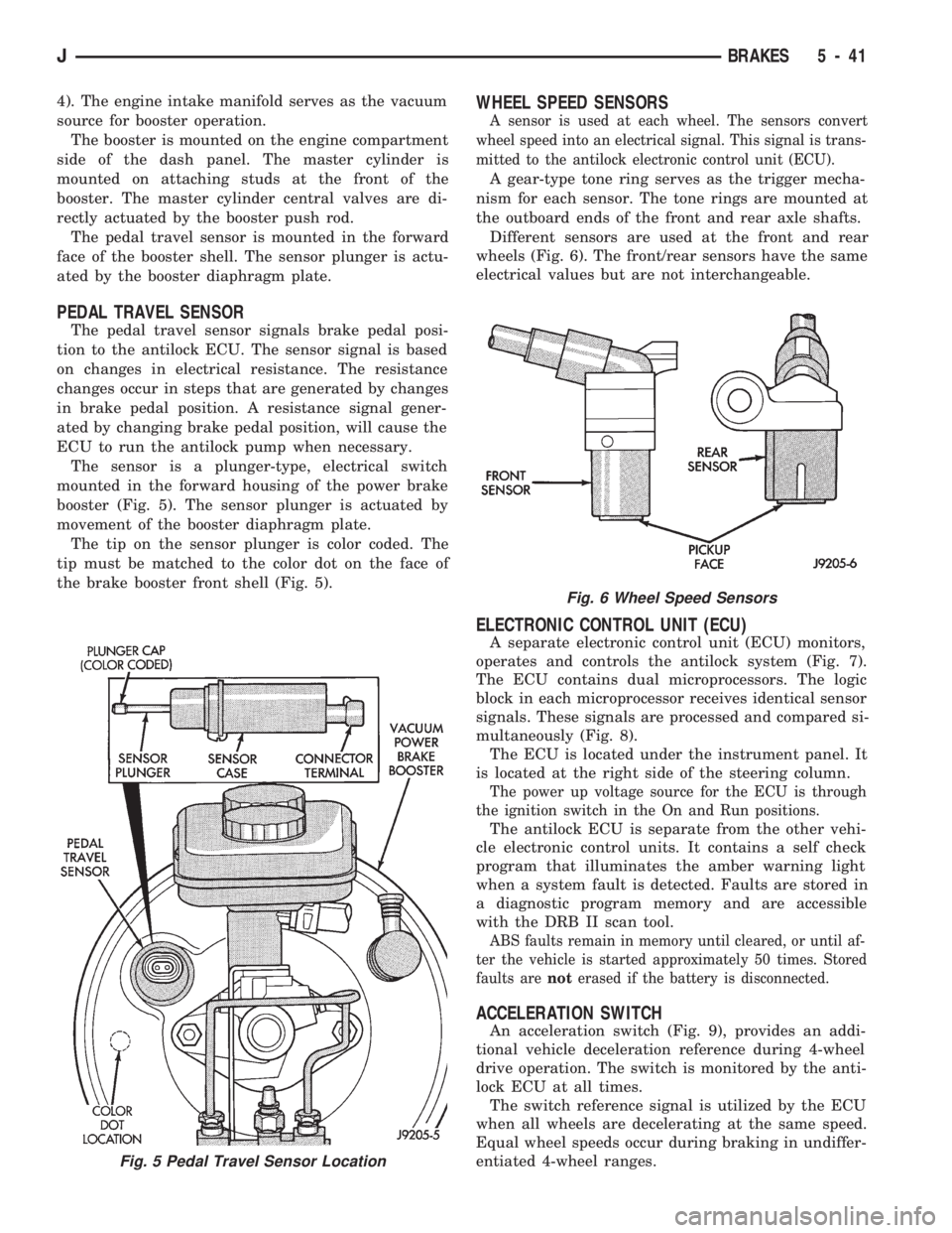
The pedal travel sensor is mounted in the forward
face of the booster shell. The sensor plunger is actu-
ated by the booster diaphragm plate.
PEDAL TRAVEL SENSOR
The pedal travel sensor signals brake pedal posi-
tion to the antilock ECU. The sensor signal is based
on changes in electrical resistance. The resistance
changes occur in steps that are generated by changes
in brake pedal position. A resistance signal gener-
ated by changing brake pedal position, will cause the
ECU to run the antilock pump when necessary.
The sensor is a plunger-type, electrical switch
mounted in the forward housing of the power brake
booster (Fig. 5). The sensor plunger is actuated by
movement of the booster diaphragm plate.
The tip on the sensor plunger is color coded. The
tip must be matched to the color dot on the face of
the brake booster front shell (Fig. 5).
WHEEL SPEED SENSORS
A sensor is used at each wheel. The sensors convert
wheel speed into an electrical signal. This signal is trans-
mitted to the antilock electronic control unit (ECU).
A gear-type tone ring serves as the trigger mecha-
nism for each sensor. The tone rings are mounted at
the outboard ends of the front and rear axle shafts.
Different sensors are used at the front and rear
wheels (Fig. 6). The front/rear sensors have the same
electrical values but are not interchangeable.
ELECTRONIC CONTROL UNIT (ECU)
A separate electronic control unit (ECU) monitors,
operates and controls the antilock system (Fig. 7).
The ECU contains dual microprocessors. The logic
block in each microprocessor receives identical sensor
signals. These signals are processed and compared si-
multaneously (Fig. 8).
The ECU is located under the instrument panel. It
is located at the right side of the steering column.
The power up voltage source for the ECU is through
the ignition switch in the On and Run positions.
The antilock ECU is separate from the other vehi-
cle electronic control units. It contains a self check
program that illuminates the amber warning light
when a system fault is detected. Faults are stored in
a diagnostic program memory and are accessible
with the DRB II scan tool.
ABS faults remain in memory until cleared, or until af-
ter the vehicle is started approximately 50 times. Stored
faults arenoterased if the battery is disconnected.
ACCELERATION SWITCH
An acceleration switch (Fig. 9), provides an addi-
tional vehicle deceleration reference during 4-wheel
drive operation. The switch is monitored by the anti-
lock ECU at all times.
The switch reference signal is utilized by the ECU
when all wheels are decelerating at the same speed.
Equal wheel speeds occur during braking in undiffer-
entiated 4-wheel ranges.
Fig. 5 Pedal Travel Sensor Location
Fig. 6 Wheel Speed Sensors
JBRAKES 5 - 41
Page 190 of 1784
ANTILOCK BRAKE SYSTEM OPERATION
INDEX
page page
ABS Operation in Antilock Braking Mode....... 43
ABS Operation in Normal Braking Mode....... 43
Acceleration Switch Operation............... 45
ECY Operation.......................... 46HCU Pump and Pedal Travel Sensor Operation . 44
HCU Solenoid Valve Operation.............. 43
System Power-Up and Initialization........... 43
Wheel Speed Sensor Operation............. 45
SYSTEM POWER-UP AND INITIALIZATION
The antilock system is in standby mode with the
ignition switch in Off or Accessory position. The an-
tilock electrical components are not operational.
Turning the ignition switch to On or Run position
allows battery voltage to flow through the switch to
the ECU ignition terminal.
The ABS system is activated when battery voltage
is supplied to the ECU. The ECU performs a system
initialization procedure at this point. Initialization
consists of a static and dynamic self check of system
electrical components.
The static check occurs immediately after the igni-
tion switch is turned to the On position. The dynamic
check occurs when vehicle road speed reaches ap-
proximately 10 kph (6 mph). During the dynamic
check, the ECU briefly cycles the pump to verify op-
eration. The HCU solenoids are checked continu-
ously.
If an ABS component exhibits a fault during ini-
tialization, the ECU illuminates the amber warning
light and registers a fault code in the microprocessor
memory.
ABS OPERATION IN NORMAL BRAKING MODE
The ECU monitors wheel speed sensor inputs con-
tinuously while the vehicle is in motion. However,
the ECU will not activate any ABS components as
long as sensor inputs and the acceleration switch in-
dicate normal braking.
During normal braking, the master cylinder, power
booster and wheel brake units all function as they
would in a vehicle without ABS. The HCU compo-
nents are not activated.
ABS OPERATION IN ANTILOCK BRAKING MODE
The purpose of the antilock system is to prevent
wheel lockup during periods of high wheel slip. Pre-
venting lockup helps maintain vehicle braking action
and steering control.
The antilock ECU activates the system whenever
sensor signals indicate periods of high wheel slip.
High wheel slip can be described as the point where
wheel rotation begins approaching zero (or lockup)
during braking. Periods of high wheel slip occur
when brake stops involve high pedal pressure and
rate of vehicle deceleration.The antilock system retards lockup during high
slip conditions by modulating fluid apply pressure to
the wheel brake units.
Brake fluid apply pressure is modulated according
to wheel speed, degree of slip and rate of decelera-
tion. A sensor at each wheel converts wheel speed
into electrical signals. These signals are transmitted
to the ECU for processing and determination of
wheel slip and deceleration rate.
The Jeep ABS system has three fluid pressure con-
trol channels. The front brakes are controlled sepa-
rately and the rear brakes in tandem (Fig. 10). A
speed sensor input signal indicating high slip condi-
tions activates the ECU antilock program.
Two solenoid valves are used in each antilock con-
trol channel (Fig. 11). The valves are all located
within the HCU valve body and work in pairs to ei-
ther increase, hold, or decrease apply pressure as
needed in the individual control channels.
The solenoid valves are not static during antilock
braking. They are cycled continuously to modulate
pressure. Solenoid cycle time in antilock mode can be
measured in milliseconds.
HCU SOLENOID VALVE OPERATION
Normal Braking
During normal braking, the HCU solenoid valves
and pump are not activated. The master cylinder and
power booster operate the same as a vehicle without
an ABS brake system.
Antilock Pressure Modulation
Solenoid valve pressure modulation occurs in three
stages which are: pressure increase, pressure hold,
and pressure decrease. The valves are all contained
in the valve body portion of the HCU.
Pressure Decrease
The outlet valve is opened and the inlet valve is
closed during the pressure decrease cycle (Fig. 11).
A pressure decrease cycle is initiated when speed
sensor signals indicate high wheel slip at one or
more wheels. At this point, the ECU opens the outlet
valve. Opening the outlet valve also opens the hy-
draulic return circuit to the master cylinder reser-
JANTILOCK BRAKE SYSTEM OPERATION 5 - 43