bulb JEEP CHEROKEE 1994 Service Repair Manual
[x] Cancel search | Manufacturer: JEEP, Model Year: 1994, Model line: CHEROKEE, Model: JEEP CHEROKEE 1994Pages: 1784, PDF Size: 77.09 MB
Page 111 of 1784
ing the IAC motor pintle in and out of the air control
passage. The IAC motor is positioned when the igni-
tion key is turned to the On position.
A (factory adjusted) set screw is used to mechani-
cally limit the position of the throttle body throttle
plate.Never attempt to adjust the engine idle
speed using this screw.All idle speed functions are
controlled by the PCM.
IGNITION COILÐPCM OUTPUT
System voltage is supplied to the ignition coil pos-
itive terminal. The powertrain control module (PCM)
operates the ignition coil.Base (initial) ignition
timing is not adjustable.The PCM adjusts ignition
timing to meet changing engine operating conditions.
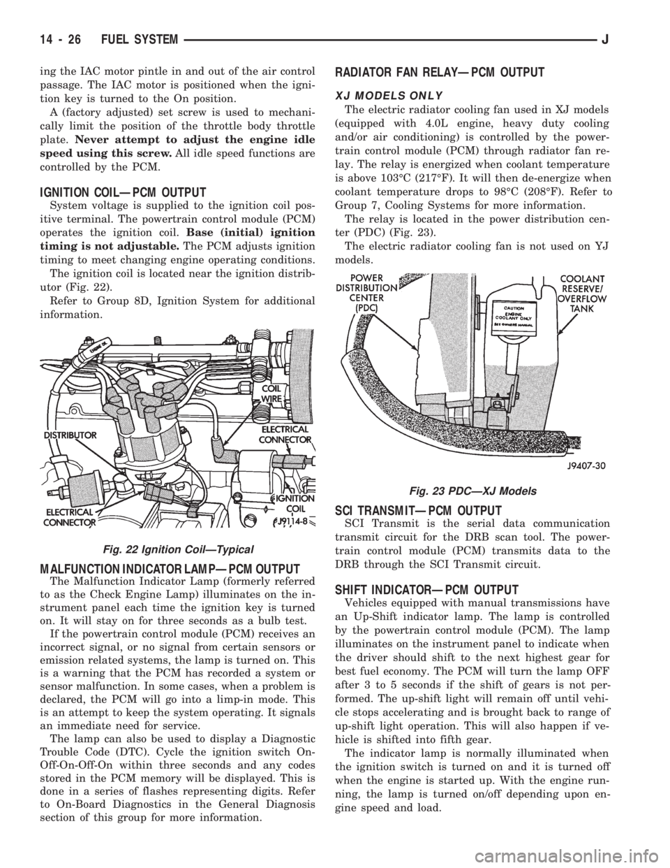
The ignition coil is located near the ignition distrib-
utor (Fig. 22).
Refer to Group 8D, Ignition System for additional
information.
MALFUNCTION INDICATOR LAMPÐPCM OUTPUT
The Malfunction Indicator Lamp (formerly referred
to as the Check Engine Lamp) illuminates on the in-
strument panel each time the ignition key is turned
on. It will stay on for three seconds as a bulb test.
If the powertrain control module (PCM) receives an
incorrect signal, or no signal from certain sensors or
emission related systems, the lamp is turned on. This
is a warning that the PCM has recorded a system or
sensor malfunction. In some cases, when a problem is
declared, the PCM will go into a limp-in mode. This
is an attempt to keep the system operating. It signals
an immediate need for service.
The lamp can also be used to display a Diagnostic
Trouble Code (DTC). Cycle the ignition switch On-
Off-On-Off-On within three seconds and any codes
stored in the PCM memory will be displayed. This is
done in a series of flashes representing digits. Refer
to On-Board Diagnostics in the General Diagnosis
section of this group for more information.
RADIATOR FAN RELAYÐPCM OUTPUT
XJ MODELS ONLY
The electric radiator cooling fan used in XJ models
(equipped with 4.0L engine, heavy duty cooling
and/or air conditioning) is controlled by the power-
train control module (PCM) through radiator fan re-
lay. The relay is energized when coolant temperature
is above 103ÉC (217ÉF). It will then de-energize when
coolant temperature drops to 98ÉC (208ÉF). Refer to
Group 7, Cooling Systems for more information.
The relay is located in the power distribution cen-
ter (PDC) (Fig. 23).
The electric radiator cooling fan is not used on YJ
models.
SCI TRANSMITÐPCM OUTPUT
SCI Transmit is the serial data communication
transmit circuit for the DRB scan tool. The power-
train control module (PCM) transmits data to the
DRB through the SCI Transmit circuit.
SHIFT INDICATORÐPCM OUTPUT
Vehicles equipped with manual transmissions have
an Up-Shift indicator lamp. The lamp is controlled
by the powertrain control module (PCM). The lamp
illuminates on the instrument panel to indicate when
the driver should shift to the next highest gear for
best fuel economy. The PCM will turn the lamp OFF
after 3 to 5 seconds if the shift of gears is not per-
formed. The up-shift light will remain off until vehi-
cle stops accelerating and is brought back to range of
up-shift light operation. This will also happen if ve-
hicle is shifted into fifth gear.
The indicator lamp is normally illuminated when
the ignition switch is turned on and it is turned off
when the engine is started up. With the engine run-
ning, the lamp is turned on/off depending upon en-
gine speed and load.
Fig. 23 PDCÐXJ Models
Fig. 22 Ignition CoilÐTypical
14 - 26 FUEL SYSTEMJ
Page 148 of 1784
BRAKES
CONTENTS
page page
ABS BRAKE DIAGNOSIS.................. 3
ABS COMPONENT SERVICE.............. 47
ABS SYSTEM OPERATION............... 39
ANTILOCK BRAKE SYSTEM OPERATION.... 43
BRAKE BLEEDINGÐBRAKE FLUID AND
LEVELÐBRAKELINES AND HOSES....... 13
BRAKE PEDAL AND BRAKELIGHT SWITCH . . 65
DISC BRAKES.......................... 24DRUM BRAKES........................ 34
GENERAL INFORMATION.................. 1
PARKING BRAKES...................... 56
POWER BRAKE BOOSTER................ 22
SERVICE BRAKE DIAGNOSIS.............. 7
SPECIFICATIONS....................... 67
STANDARD MASTER CYLINDER........... 20
GENERAL INFORMATION
INDEX
page page
Antilock Brake System (ABS)................ 1
Brake Fluid/Lubricants/Cleaning Solvents........ 1
Brake Safety Precautions................... 2
Brake Warning Lights...................... 1
Brakelining Material........................ 1Hydraulic Components..................... 1
Jeep Body Code Letters.................... 2
Power Brakes............................ 1
Wheel Brake Components................... 1
WHEEL BRAKE COMPONENTS
Front disc and rear drum brakes are used on all
models. The disc brake components consist of single
piston calipers and ventilated rotors. The rear drum
brakes are dual shoe, units with cast brake drums.
The parking brake mechanism is lever and cable
operated. The cables are attached to actuating levers
mounted on the rear drum brake secondary shoes.
The parking brake mechanism is operated by a foot
pedal on YJ models and a hand lever on XJ models.
POWER BRAKES
Power brakes are standard on all models. A vac-
uum operated power booster is used for standard and
ABS brake applications.
HYDRAULIC COMPONENTS
A dual reservoir master cylinder is used for all
standard brake applications. A combination propor-
tioning valve/pressure differential switch is used. A
center feed style master cylinder is used for ABS
brake applications.
BRAKELINING MATERIAL
The factory installed brakelining on all models con-
sists of an organic base material combined with me-
tallic particles. The lining does not contain asbestos.
BRAKE WARNING LIGHTS
A red, brake warning light is used to alert the
driver if a pressure differential exists between the
front and rear hydraulic systems. The light also
alerts the driver when the parking brakes are ap-
plied. The light illuminates for a few seconds at start
up as part of a bulb check procedure.
An additional warning light is used on models with
antilock brakes. This light is amber in color and is
located in the same side of the instrument cluster as
the red warning light. The amber light illuminates
only when an ABS system fault occurs.
ANTILOCK BRAKE SYSTEM (ABS)
An antilock brake system (ABS) is available on
XJ/YJ models. The system is an electronically oper-
ated, all-wheel brake control system. The ABS sys-
tem is designed to retard wheel lockup during
periods of high wheel slip braking. Refer to the anti-
lock brake section for operation and service informa-
tion.
BRAKE FLUID/LUBRICANTS/CLEANING SOLVENTS
Recommended fluid for all Jeep vehicles is Mopar
DOT 3 brake fluid, or an equivalent meeting SAE
J1703 and DOT 3 standards.
JBRAKES 5 - 1
Page 155 of 1784
(2) If red warning light is illuminated, or if neither
warning light is illuminated, make several stops and
note pedal action and brake response.
(3) Check brake pedal response with transmission
in Neutral and engine running. Pedal should remain
firm under steady foot pressure. If pedal falls away,
problem is either in vacuum booster or master cylin-
der.
(4) During road test, make normal and firm brake
stops in 25-40 mph range. Note faulty brake opera-
tion such as pull, grab, drag, noise, fade, pedal pul-
sation, etc.
(5) Inspect suspect brake components and refer to
problem diagnosis information for causes of various
brake conditions.
COMPONENT INSPECTION
Fluid leak points and dragging brake units can
usually be located without removing any compo-
nents. The area around a leak point will be wet with
fluid. The components at a dragging brake unit
(wheel, tire, rotor) will be quite warm or hot to the
touch.
Other brake problem conditions will require compo-
nent removal for proper inspection. Raise the vehicle
and remove the necessary wheels for better visual ac-
cess.
During component inspection, pay particular atten-
tion to heavily rusted/corroded brake components
(e.g. rotors, caliper pistons, brake return/holddown
springs, support plates, etc.).
Heavy accumulations of rust may be covering se-
vere damage to a brake component. It is wise to re-
move surface rust in order to accurately determine
the depth of rust penetration and damage. Light sur-
face rust is fairly normal and not a major concern (as
long as it is removed). However, heavy rust buildup,
especially on high mileage vehicles may cover struc-
tural damage to such important components as
brakelines, rotors, support plates, and brake boosters.
Refer to the wheel brake service procedures in this
group for more information.
DIAGNOSING SERVICE BRAKE PROBLEMS
BRAKE WARNING LIGHT OPERATION
The red brake warning light will illuminate under
the following conditions:
²for 2-3 seconds at startup as part of normal bulb
check
²parking brakes applied
²low pedal caused by malfunction in front/rear
brake hydraulic circuit (differential switch valve ac-
tuated)
If the red light remains on after startup, first ver-
ify that the parking brakes are fully released. Then
check pedal action and fluid level. A red light indi-
cates that the valve in the differential pressureswitch has been actuated. If a problem is confirmed,
inspect the hydraulic system and wheel brake compo-
nents.
On models with ABS brakes, the amber warning
light only illuminates when an ABS component has
malfunctioned. The ABS light operates indepen-
dently of the red warning light. Refer to the antilock
brake section for more detailed diagnosis informa-
tion.
PEDAL FALLS AWAY
A brake pedal that falls away under steady foot
pressure is generally the result of a system leak. The
leak point could be at a brakeline, fitting, hose,
wheel cylinder, or caliper. Internal leakage in the
master cylinder caused by worn or damaged piston
cups, may also be the problem cause.
If leakage is severe, fluid will be evident at or
around the leaking component. However internal
leakage in the master cylinder will not be physically
evident. Refer to the cylinder test procedure in this
section.
LOW PEDAL
If a low pedal is experienced, pump the pedal sev-
eral times. If the pedal comes back up, worn lining
and worn rotors or drums are the most likely causes.
However, if the pedal remains low and/or the warn-
ing light illuminates, the problem is in the master
cylinder, wheel cylinders, or calipers.
A decrease in master cylinder fluid level may only
be the result of normal lining wear. Fluid level will
decrease as lining wear occurs. It is a result of the
outward movement of caliper and wheel cylinder pis-
tons to compensate for normal wear.
SPONGY PEDAL
A spongy pedal is most often caused by air in the
system. However, thin drums or substandard brake
lines and hoses will also cause a condition similar to
a spongy pedal. The proper course of action is to
bleed the system, or replace thin drums and suspect
quality brake lines and hoses.
HARD PEDAL OR HIGH PEDAL EFFORT
A hard pedal or high pedal effort may be due to
lining that is water soaked, contaminated, glazed, or
badly worn. The power booster or check valve could
also be faulty. Test the booster and valve as de-
scribed in this section.
BRAKE DRAG
Brake drag occurs when the lining is in constant
contact with the rotor or drum. Drag can occur at
one wheel, all wheels, fronts only, or rears only. It is
a product of incomplete brakeshoe release. Drag can
be minor or severe enough to overheat the linings,
rotors and drums.
5 - 8 BRAKESJ
Page 276 of 1784
BATTERY TESTING GENERAL INFORMATION
Before testing a battery, clean the top of the
battery case, posts and cable terminals.
Specific gravity is a ratio of the density of the elec-
trolyte and the density of pure water. The electrolyte
is composed of sulfuric acid and water. Acid makes
up approximately 35% of the electrolyte by weight,
or 24% by volume.
The condition of a battery may be determined from
the results of 2 tests:
²hydrometer test
²ability to supply current (battery load test)
Perform the hydrometer test first. If the specific
gravity is less than 1.235, (with battery at room tem-
perature) the battery must be charged before pro-
ceeding with further testing. A battery that will not
accept a charge is defective and further testing is not
necessary.
Completely discharged batteries may take sev-
eral hours to accept a charge. See Charging
Completely Discharged Battery.
A battery that has been fully charged but does not
pass the battery load test is defective.
A battery is fully charged when:
²all cells are gassing freely during charging
²3 corrected specific gravity tests, taken at 1-hour
intervals, indicate no increase in specific gravity.
ABNORMAL BATTERY DISCHARGING
(1) Corroded battery posts and terminals.
(2) Loose or worn generator drive belt.
(3) Electrical loads that exceed the output of the
charging system due to equipment or accessories in-
stalled after delivery.
(4) Slow driving speeds (heavy traffic conditions)
or prolonged idling with high-amperage draw sys-
tems in use.
(5) Defective circuit or component causing excess
IOD. Refer to Ignition Off Draw Diagnosis in this
group.
(6) Defective charging system.
(7) Defective battery.
HYDROMETER TEST
Before performing a hydrometer test, remove
battery caps and check electrolyte level. Add
distilled water as required.
Before testing, visually inspect battery for any
damage (cracked case or cover, loose post, etc.) that
would cause the battery to be defective. To use the
hydrometer correctly, hold it with the top surface of
the electrolyte at eye level. Refer to manufacturers
instructions for correct use of hydrometer.
Remove only enough electrolyte from the battery to
keep the float off the bottom of the hydrometer bar-
rel with pressure on the bulb released. Exercise care
when inserting the tip of the hydrometer into a cellto avoid damage to the separators. Damaged separa-
tors can cause premature battery failure.
Hydrometer floats are generally calibrated to indi-
cate the specific gravity correctly only at one fixed
temperature, 80ÉF (26.6ÉC). When testing the specific
gravity at any other temperature, a correction factor
is required.
The correction factor is approximately a specific
gravity value of 0.004, referred to as 4 points of spe-
cific gravity. For each 10ÉF above 80ÉF (5.5ÉC above
26.6ÉC), add 4 points. For each 10ÉF below 80ÉF
(5.5ÉC below 26.6ÉC), subtract 4 points. Always cor-
rect the specific gravity for temperature variation.
Test the specific gravity of the electrolyte in each
battery cell.
Example: A battery is tested at 10ÉF (-12.2ÉC) and
has a specific gravity of 1.240. Determine the actual
specific gravity as follows:
²Determine the number of degrees above or below
80ÉF:
80ÉF - 10ÉF = 70ÉF
²Divide the result above by 10:
70ÉF/10 = 7
²Multiply the result from the previous step by the
temperature correction factor (0.004):
7 x 0.004 = 0.028
²The temperature at testing was below 80ÉF, there-
fore the temperature correction is subtracted:
1.240 - 0.028 = 1.212
²The corrected specific gravity is 1.212.
The fully charged battery should have a tempera-
ture corrected specific gravity of 1.260 to 1.290.
If the specific gravity of all cells is above 1.235,
and cell variation is more than 50 points (0.050), it is
an indication that the battery is unserviceable.
If the specific gravity of one or more cells is less
than 1.235, charge the battery at a rate of approxi-
mately 5 amperes. Continue charging until 3 consec-
utive specific gravity tests, taken at 1 hour intervals,
are constant.
If the cell specific gravity variation is more than 50
points (0.050) after the charge period, replace the
battery.
When the specific gravity of all cells is above 1.235
and variation between cells is less than 50 points
(0.050), the battery may be tested under heavy load.
BATTERY OPEN CIRCUIT VOLTAGE TEST
A battery voltage (no load) test will show state of
charge of a battery that will pass the Battery Load
Test described in this section.Before proceeding
with this test or Battery Load Test, completely
charge battery as described in Battery Charging
in this section.
If a battery has a no load voltage reading of 12.4
volts or greater and will not endure a load test, it is
defective and should be replaced. Refer to Group 8B -
JBATTERY/STARTING/CHARGING SYSTEMS DIAGNOSTICS 8A - 3
Page 281 of 1784
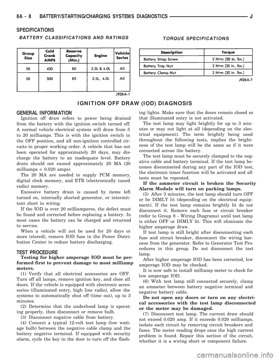
SPECIFICATIONS
IGNITION OFF DRAW (IOD) DIAGNOSIS
GENERAL INFORMATION
Ignition off draw refers to power being drained
from the battery with the ignition switch turned off.
A normal vehicle electrical system will draw from 5
to 20 milliamps. This is with the ignition switch in
the OFF position, and all non-ignition controlled cir-
cuits in proper working order. A vehicle that has not
been operated for approximately 20 days, may dis-
charge the battery to an inadequate level. Battery
drain should not exceed approximately 20 MA (20
milliamps = 0.020 amps).
The 20 MA are needed to supply PCM memory,
digital clock memory, and ETR (electronically tuned
radio) memory.
Excessive battery drain is caused by items left
turned on, internally shorted generator, or intermit-
tent short in wiring.
If the IOD is over 20 milliamperes, the defect must
be found and corrected before replacing a battery. In
most cases the battery can be charged and returned
to service.
When a vehicle will not be used for 20 days or
more (stored), remove IOD fuse in the Power Distri-
bution Center to reduce battery discharging.
TEST PROCEDURE
Testing for higher amperage IOD must be per-
formed first to prevent damage to most milliamp
meters.
(1) Verify that all electrical accessories are OFF.
Turn off all lamps, remove ignition key, and close all
doors. If the vehicle is equipped with electronic acces-
sories (illuminated entry, high line radio), allow the
systems to automatically shut off (time out), up to 3
minutes.
(2) Determine that the underhood lamp is operat-
ing properly, then disconnect or remove bulb.
(3) Disconnect negative cable from battery.
(4) Connect a typical 12-volt test lamp (low watt-
age bulb) between the negative cable clamp and the
battery negative terminal. If equipped with security
alarm, cycle the key in the door to turn off the flash-ing lights. Make sure that the doors remain closed so
that illuminated entry is not activated.
The test lamp may light brightly for up to 3 min-
utes or may not light at all (depending on the elec-
trical equipment). The term brightly being used
throughout the following tests, implies the bright-
ness of the test lamp will be the same as if it were
connected across the battery.
The test lamp must be securely clamped to the neg-
ative cable and battery terminal. If the test lamp be-
comes disconnected during any part of the IOD test,
the electronic timer function will be activated and all
tests must be repeated.
If the ammeter circuit is broken the Security
Alarm Module will turn on parking lamps.
(5) After 3 minutes, the test lamp should turn OFF
or be DIMLY lit (depending on the electrical equip-
ment). If the test lamp remains brightly lit do not
disconnect it. Remove each fuse or circuit breaker
(refer to Group 8 - Wiring Diagrams) until test lamp
is either OFF or DIMLY lit. This will eliminate the
higher amperage draw.
If test lamp is still bright after disconnecting each
fuse and circuit breaker, disconnect the wiring har-
ness from the generator. Refer to Generator Test Pro-
cedures in this group. Do not disconnect the test
lamp.
After higher amperage IOD has been corrected, low
amperage IOD may be checked.
It is now safe to install milliamp meter to check for
low amperage IOD.
(6) With test lamp still connected securely, clamp
an ammeter between battery negative terminal and
negative battery cable.
Do not open any doors or turn on any electri-
cal accessories with the test lamp disconnected
or the meter may be damaged.
(7) Disconnect test lamp. The current draw should
not exceed 0.020 amp. If it exceeds 0.020 milliamps,
isolate each circuit by removing circuit breakers and
fuses. The meter reading drops once the high current
problem is found. Repair this section of the circuit,
whether it is a wiring short or component failure.
BATTERY CLASSIFICATIONS AND RATINGSTORQUE SPECIFICATIONS
8A - 8 BATTERY/STARTING/CHARGING SYSTEMS DIAGNOSTICSJ
Page 287 of 1784
GENERATOR TEST PROCEDURES ON VEHICLE
INDEX
page page
Diagnostic Procedures..................... 15
General Information....................... 14Operational Check with Battery Indicator
(Base Cluster Only)..................... 14
Operational Check with Voltmeter............ 15
GENERAL INFORMATION
The generator is belt-driven by the engine. All en-
gines use serpentine drive.
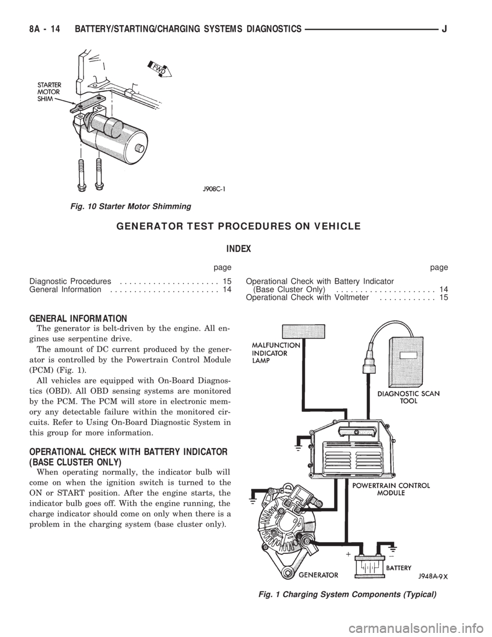
The amount of DC current produced by the gener-
ator is controlled by the Powertrain Control Module
(PCM) (Fig. 1).
All vehicles are equipped with On-Board Diagnos-
tics (OBD). All OBD sensing systems are monitored
by the PCM. The PCM will store in electronic mem-
ory any detectable failure within the monitored cir-
cuits. Refer to Using On-Board Diagnostic System in
this group for more information.
OPERATIONAL CHECK WITH BATTERY INDICATOR
(BASE CLUSTER ONLY)
When operating normally, the indicator bulb will
come on when the ignition switch is turned to the
ON or START position. After the engine starts, the
indicator bulb goes off. With the engine running, the
charge indicator should come on only when there is a
problem in the charging system (base cluster only).
Fig. 10 Starter Motor Shimming
Fig. 1 Charging System Components (Typical)
8A - 14 BATTERY/STARTING/CHARGING SYSTEMS DIAGNOSTICSJ
Page 288 of 1784
OPERATIONAL CHECK WITH VOLTMETER
When the ignition switch is turned to the ON po-
sition, battery potential will register on the voltme-
ter. During engine cranking a lower voltage will
appear on the meter. With the engine running, a
voltage reading higher than the first reading (igni-
tion in ON) should register.
DIAGNOSTIC PROCEDURES
If the indicator operates abnormally, or if an un-
dercharged or overcharged battery condition occurs,
the following procedures may be used to diagnose the
charging system.
Remember that an undercharged battery is often
caused by:
²accessories being left on overnight
²or by a defective switch which allows a bulb, such
as a liftgate or glove box light, to stay on (refer to
Ignition Off Draw Diagnosis).
VISUAL INSPECTION
²Inspect condition of battery cable terminals, bat-
tery posts, connections at engine block, starter motor
solenoid and relay. They should be clean and tight.
Repair as required.
²Inspect all fuses in the fuse block for tightness in
receptacles. They should be properly installed and
tight. Repair or replace as required.²Inspect the electrolyte level in the battery and add
water if necessary.
²Inspect generator mounting bolts for tightness. Re-
place or torque bolt as required. Refer to Torque
Specifications in Battery/Starter/Generator Service.
²Inspect generator drive belt condition and tension.
Tension or replace belt as required. Refer to Belt
Tension Specifications in Battery/Starter/Generator
Service.
²Inspect connection at generator B+ output. It
should be clean and tight. Repair as required.
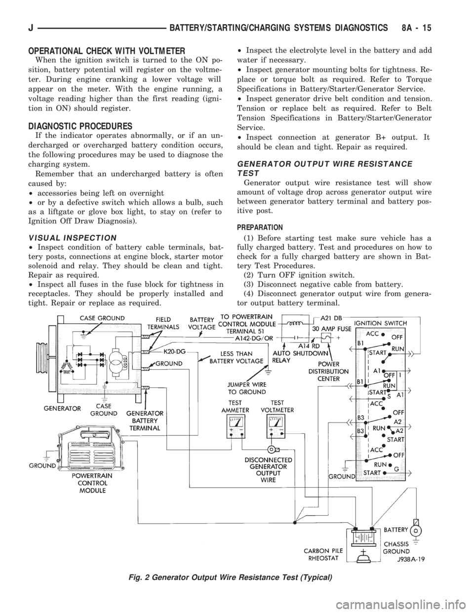
GENERATOR OUTPUT WIRE RESISTANCE
TEST
Generator output wire resistance test will show
amount of voltage drop across generator output wire
between generator battery terminal and battery pos-
itive post.
PREPARATION
(1) Before starting test make sure vehicle has a
fully charged battery. Test and procedures on how to
check for a fully charged battery are shown in Bat-
tery Test Procedures.
(2) Turn OFF ignition switch.
(3) Disconnect negative cable from battery.
(4) Disconnect generator output wire from genera-
tor output battery terminal.
Fig. 2 Generator Output Wire Resistance Test (Typical)
JBATTERY/STARTING/CHARGING SYSTEMS DIAGNOSTICS 8A - 15
Page 312 of 1784
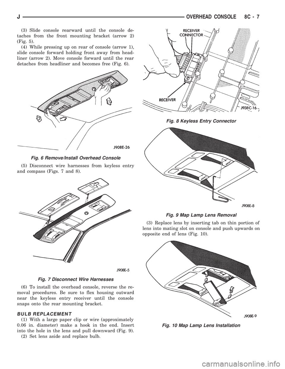
(3) Slide console rearward until the console de-
taches from the front mounting bracket (arrow 2)
(Fig. 5).
(4) While pressing up on rear of console (arrow 1),
slide console forward holding front away from head-
liner (arrow 2). Move console forward until the rear
detaches from headliner and becomes free (Fig. 6).
(5) Disconnect wire harnesses from keyless entry
and compass (Figs. 7 and 8).
(6) To install the overhead console, reverse the re-
moval procedures. Be sure to flex housing outward
near the keyless entry receiver until the console
snaps onto the rear mounting bracket.
BULB REPLACEMENT
(1) With a large paper clip or wire (approximately
0.06 in. diameter) make a hook in the end. Insert
into the hole in the lens and pull downward (Fig. 9).
(2) Set lens aside and replace bulb.(3) Replace lens by inserting tab on thin portion of
lens into mating slot on console and push upwards on
opposite end of lens (Fig. 10).
Fig. 6 Remove/Install Overhead Console
Fig. 7 Disconnect Wire Harnesses
Fig. 8 Keyless Entry Connector
Fig. 9 Map Lamp Lens Removal
Fig. 10 Map Lamp Lens Installation
JOVERHEAD CONSOLE 8C - 7
Page 348 of 1784
INSTRUMENT PANEL AND GAUGES
GROUP INDEX
page page
INSTRUMENT PANEL AND GAUGESÐXJ..... 1INSTRUMENT PANEL AND GAUGESÐYJ.... 14
INSTRUMENT PANEL AND GAUGESÐXJE
CONTENTS
page page
INSTRUMENT CLUSTER DIAGNOSIS........ 3
INSTRUMENT CLUSTER GENERAL INFORMATION.. 1
INSTRUMENT CLUSTER SERVICE PROCEDURES... 5
SPECIFICATIONS....................... 13
INSTRUMENT CLUSTER GENERAL INFORMATION
INDEX
page page
4WD Indicator Lamp........................ 2
Anti-Lock Brake Indicator Lamp............... 2
Brake Indicator Lamp....................... 2
Coolant Temperature Gauge................. 1
Coolant Temperature Indicator Lamp........... 1
Fuel Gauge.............................. 2
Low Fuel Warning Lamp..................... 2Malfunction Indicator Lamp (Check Engine)...... 2
Oil Pressure Gauge....................... 1
Oil Pressure Indicator Lamp.................. 1
Speedometer/Odometer System.............. 2
Tachometer.............................. 2
Upshift Indicator Lamp...................... 2
Voltmeter............................... 1
With the ignition switch in the ON or START posi-
tion, voltage supplied to the instrument cluster is lim-
ited by fuse #17. The voltage is supplied to all the
gauges and indicator lamps through the instrument
cluster printed circuit.
With the ignition switch in the OFF position, volt-
age is not supplied to the instrument cluster and the
gauges do not indicate any vehicle condition.
VOLTMETER
The voltmeter measures battery or generator out-
put voltage, whichever is greater.
OIL PRESSURE GAUGE
The oil pressure gauge pointer position is controlled
by a magnetic field created by electrical current flow
through the coils within the gauge. A change in current
flow will change the magnetic field which changes the
pointer position. The oil pressure sender is a variable
resistor that changes electrical resistance with a change
in oil pressure (values shown in Specifications chart).
OIL PRESSURE INDICATOR LAMP
Voltage is supplied to one side of the indicator bulb
and the oil pressure switch is connected to the other
side. When oil pressure is too low the switch closes
providing a path to ground, and the indicator bulb
lights.
COOLANT TEMPERATURE GAUGE
The coolant temperature gauge pointer position is
controlled by a magnetic field created by electrical
current flow through the coils within the gauge. A
change in current flow will change the magnetic field
which changes the pointer position. The coolant tem-
perature sensor is a thermistor that changes electri-
cal resistance with a change in coolant temperature
(values shown in Specifications chart).
COOLANT TEMPERATURE INDICATOR LAMP
Voltage is supplied to one side of the indicator bulb
and the coolant temperature switch is connected to the
JINSTRUMENT PANEL AND GAUGES 8E - 1
Page 349 of 1784
other side. When coolant temperature is too high the
switch closes providing a path to ground, and the indi-
cator bulb lights.
TACHOMETER
The tachometer displays the engine speed (RPM).
With the engine running, the tachometer receives an
engine speed signal from the Powertrain Control
Module pin 43 (values shown in Specifications chart).
SPEEDOMETER/ODOMETER SYSTEM
The speedometer/odometer system consists of an elec-
tric speedometer and pushbutton reset odometer
mounted in the cluster. The system also includes the
wire harness from the cluster to the vehicle speed sen-
sor at the transmission, and the adapter and pinion in
the transmission. A signal is sent from a transmission
mounted vehicle speed sensor to the speedometer/odom-
eter circuitry through the wiring harness. Refer to
Group 21 - Transmission for selecting the proper pinion,
and selecting and indexing the proper adapter.
FUEL GAUGE
The fuel gauge pointer position is controlled by a
magnetic field created by electrical current flow through
the coils within the gauge. A change in current flow will
change the magnetic field which changes the pointer po-
sition. The fuel level sender is a variable resistor that
changes electrical resistance with a change of the level
of fuel in the tank (values shown in Specifications
chart).
LOW FUEL WARNING LAMP
The low fuel warning lamp will light when the fuel
level falls below approximately 4 gallons. A low fuel
warning module controls when the lamp will light.
When the module senses 66.5 ohms or less from the
fuel level sender for 10 continuous seconds, the lamp
will light. The lamp will remain on until the module
senses 63.5 ohms or more from the fuel level sender
for 20 continuous seconds.
UPSHIFT INDICATOR LAMP
Vehicles equipped with manual transmissions have an
optional upshift indicator lamp. The lamp is controlled
by the Powertrain Control Module. The lamp lights to
indicate when the driver should shift to the next high-
est gear for best fuel economy. The Powertrain Control
Module will turn the lamp off after 3 to 5 seconds if the
upshift is not performed. The lamp will remain off until
the vehicle stops accelerating and is brought back to the
range of lamp operation or shifted into another gear.
The indicator lamp is normally illuminated when
the ignition switch is turned ON and is turned off
when the engine is started. The lamp will be lighted
during engine operation according to engine speed
and load.
BRAKE INDICATOR LAMP
The brake indicator lamp warns the driver that the
parking brake is applied or that hydraulic pressure in
the split brake system is unequal.
Voltage is supplied through the brake indicator
bulb to 3 switches. A path to ground for the current
is available if:
²The brake warning switch is closed (with unequal
brake system hydraulic pressures), or
²
The ignition switch is in the START position (to test
the bulb), or
²The park brake switch is closed (with the parking
brake applied).
ANTI-LOCK BRAKE SYSTEM (ABS) INDICATOR
LAMP
The anti-lock brake system (ABS) lamp lights to in-
dicate a system self-check is in process at vehicle
start-up. If light remains on after start-up or comes
on and stays on while driving, it may indicate that
the ABS system has detected a malfunction or has
become inoperative.
4WD INDICATOR LAMP
COMMAND-TRAC 4WD
The PART TIME lamp lights when the vehicle is en-
gaged in four-wheel drive mode. Voltage is supplied to
one side of the indicator bulb. A switch in the transfer
case area is connected to the other side of the indicator
bulb. When the switch is closed, a path to ground is pro-
vided and the indicator bulb lights.
SELECT-TRAC 4WD
The four-wheel drive icon or FULL TIME lamp
lights when the vehicle is engaged in full time four-
wheel drive mode. The PART TIME lamp lights when
the vehicle is in part time four-wheel drive mode.
Voltage is supplied to one side of the indicators.
Switches in the transfer case area are connected to
the other side of the indicator bulbs. When a switch
is closed, a path to ground is provided and the indi-
cator bulb lights.
MALFUNCTION INDICATOR LAMP (CHECK ENGINE)
The Malfunction Indicator Lamp (Check Engine)
lights each time the ignition switch is turned ON and
stays on for 3 seconds as a bulb test.
If the PCM receives an incorrect signal or no signal
from certain sensors or emission related systems the
lamp is turned on (pin 32 of PCM). This is a warning
that the PCM has recorded a system or sensor mal-
function. In some cases when a diagnostic trouble
code is declared the PCM will go into a limp-in mode
in an attempt to keep the system operating. It sig-
nals an immediate need for service.
The lamp also can be used to display diagnostic
trouble codes (DTC). Cycle the ignition switch ON,
OFF, ON, OFF, ON within 5 seconds. This will allow
any trouble codes stored in the PCM memory to be
displayed in a series of flashes representing digits.
8E - 2 XJ INSTRUMENT PANEL AND GAUGESJ