JEEP CHEROKEE 1995 Service Repair Manual
Manufacturer: JEEP, Model Year: 1995, Model line: CHEROKEE, Model: JEEP CHEROKEE 1995Pages: 2198, PDF Size: 82.83 MB
Page 101 of 2198
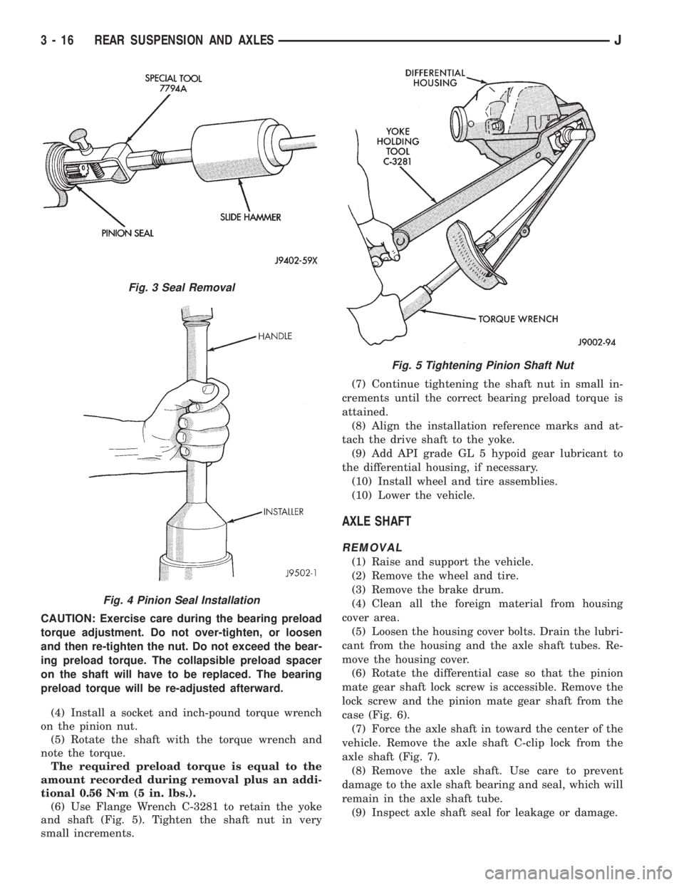
CAUTION: Exercise care during the bearing preload
torque adjustment. Do not over-tighten, or loosen
and then re-tighten the nut. Do not exceed the bear-
ing preload torque. The collapsible preload spacer
on the shaft will have to be replaced. The bearing
preload torque will be re-adjusted afterward.
(4) Install a socket and inch-pound torque wrench
on the pinion nut.
(5) Rotate the shaft with the torque wrench and
note the torque.
The required preload torque is equal to the
amount recorded during removal plus an addi-
tional 0.56 Nzm (5 in. lbs.).
(6) Use Flange Wrench C-3281 to retain the yoke
and shaft (Fig. 5). Tighten the shaft nut in very
small increments.(7) Continue tightening the shaft nut in small in-
crements until the correct bearing preload torque is
attained.
(8) Align the installation reference marks and at-
tach the drive shaft to the yoke.
(9) Add API grade GL 5 hypoid gear lubricant to
the differential housing, if necessary.
(10) Install wheel and tire assemblies.
(10) Lower the vehicle.
AXLE SHAFT
REMOVAL
(1) Raise and support the vehicle.
(2) Remove the wheel and tire.
(3) Remove the brake drum.
(4) Clean all the foreign material from housing
cover area.
(5) Loosen the housing cover bolts. Drain the lubri-
cant from the housing and the axle shaft tubes. Re-
move the housing cover.
(6) Rotate the differential case so that the pinion
mate gear shaft lock screw is accessible. Remove the
lock screw and the pinion mate gear shaft from the
case (Fig. 6).
(7) Force the axle shaft in toward the center of the
vehicle. Remove the axle shaft C-clip lock from the
axle shaft (Fig. 7).
(8) Remove the axle shaft. Use care to prevent
damage to the axle shaft bearing and seal, which will
remain in the axle shaft tube.
(9) Inspect axle shaft seal for leakage or damage.
Fig. 3 Seal Removal
Fig. 4 Pinion Seal Installation
Fig. 5 Tightening Pinion Shaft Nut
3 - 16 REAR SUSPENSION AND AXLESJ
Page 102 of 2198

(10) Inspect the roller bearing contact surface on
the axle shaft for signs of brinelling, spalling and pit-
ting.
(11) If any of these conditions exist, the axle shaft
and bearing or seal must be replaced.
INSTALLATION
(1) Lubricate the bearing bore and seal lip with
gear lubricant. Insert the axle shaft through the seal,
bearing, and engage it with the side gear splines.
Use care to prevent the shaft splines from dam-
aging the axle shaft seal lip.
(2) Insert the C-clip lock in the end of the axle
shaft. Push the axle shaft outward to seat the C-clip
lock in the side gear.
(3) Insert the mate shaft into the case and through
the thrust washers and pinion gears. Align the hole
in shaft with the hole in the differential case and in-
stall the lock screw with Loctiteton the threads.
Tighten the screw to 19 Nzm (14 ft. lbs.) torque.
(4) Install the cover and add fluid. Refer to the
Drain and Refill in this section.
AXLE SHAFT SEAL AND BEARING
REMOVAL
(1) Remove the axle shaft. Refer to the Removal
procedures in this Group.
(2) Remove the axle shaft seal from the end of the
axle shaft tube with a small pry bar.
(3) Remove the bearing if it appears damaged.
The seal and bearing can be removed at the same
time with the bearing removal tool.
(4) Remove the axle shaft bearing from the tube
(Fig. 8) with Bearing Removal Tool Set 6310 (T.Ar
960-02).
(5) Inspect the axle shaft tube bore for roughness
and burrs. Remove as necessary.
CAUTION: Inspect the housing bore for burrs. Re-
move them if they exist.
INSTALLATION
Do not install the original axle shaft seal. Al-
ways install a new seal.
(1) Wipe the bore in the axle shaft tube clean.
(2) Install axle shaft bearing with Installer 6436
and Handle C-4171. Ensure part number on the
bearing must go against the Installer.
(3) Install the new axle shaft seal (Fig. 9) with In-
staller 6437 and Handle C-4171.
(4) Install the Axle Shaft. Refer to the installation
procedure.
Fig. 6 Mate Shaft Lock Screw
Fig. 7 Axle Shaft C-Clip Lock
Fig. 8 Axle Shaft Bearing Removal Tool
JREAR SUSPENSION AND AXLES 3 - 17
Page 103 of 2198
DIFFERENTIAL REMOVAL
To service the differential the axle shafts must be
removed. Refer to the removal procedures in this
Group.
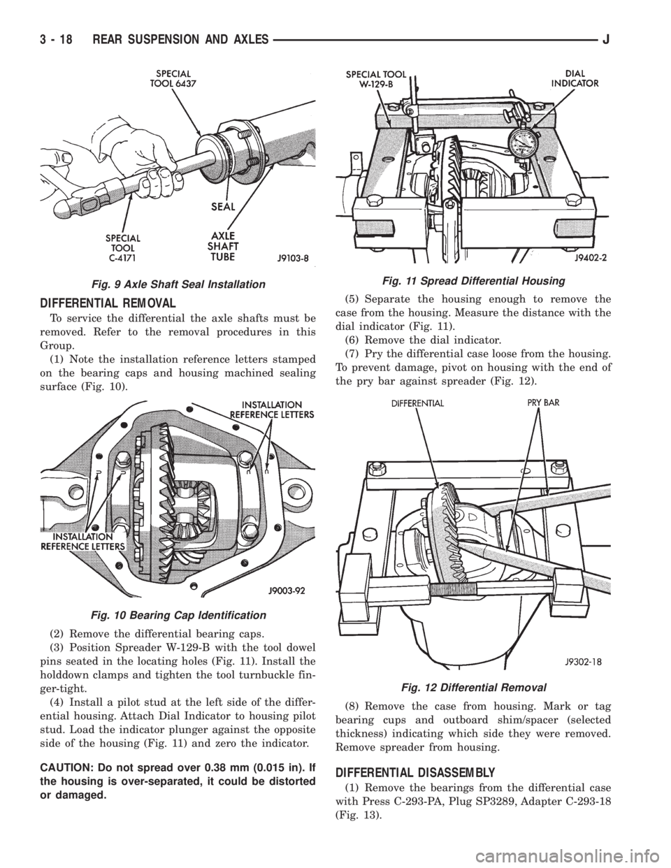
(1) Note the installation reference letters stamped
on the bearing caps and housing machined sealing
surface (Fig. 10).
(2) Remove the differential bearing caps.
(3) Position Spreader W-129-B with the tool dowel
pins seated in the locating holes (Fig. 11). Install the
holddown clamps and tighten the tool turnbuckle fin-
ger-tight.
(4) Install a pilot stud at the left side of the differ-
ential housing. Attach Dial Indicator to housing pilot
stud. Load the indicator plunger against the opposite
side of the housing (Fig. 11) and zero the indicator.
CAUTION: Do not spread over 0.38 mm (0.015 in). If
the housing is over-separated, it could be distorted
or damaged.(5) Separate the housing enough to remove the
case from the housing. Measure the distance with the
dial indicator (Fig. 11).
(6) Remove the dial indicator.
(7) Pry the differential case loose from the housing.
To prevent damage, pivot on housing with the end of
the pry bar against spreader (Fig. 12).
(8) Remove the case from housing. Mark or tag
bearing cups and outboard shim/spacer (selected
thickness) indicating which side they were removed.
Remove spreader from housing.
DIFFERENTIAL DISASSEMBLY
(1) Remove the bearings from the differential case
with Press C-293-PA, Plug SP3289, Adapter C-293-18
(Fig. 13).
Fig. 9 Axle Shaft Seal Installation
Fig. 10 Bearing Cap Identification
Fig. 11 Spread Differential Housing
Fig. 12 Differential Removal
3 - 18 REAR SUSPENSION AND AXLESJ
Page 104 of 2198
Place adapter rings so they do not damage
the bearing cage.
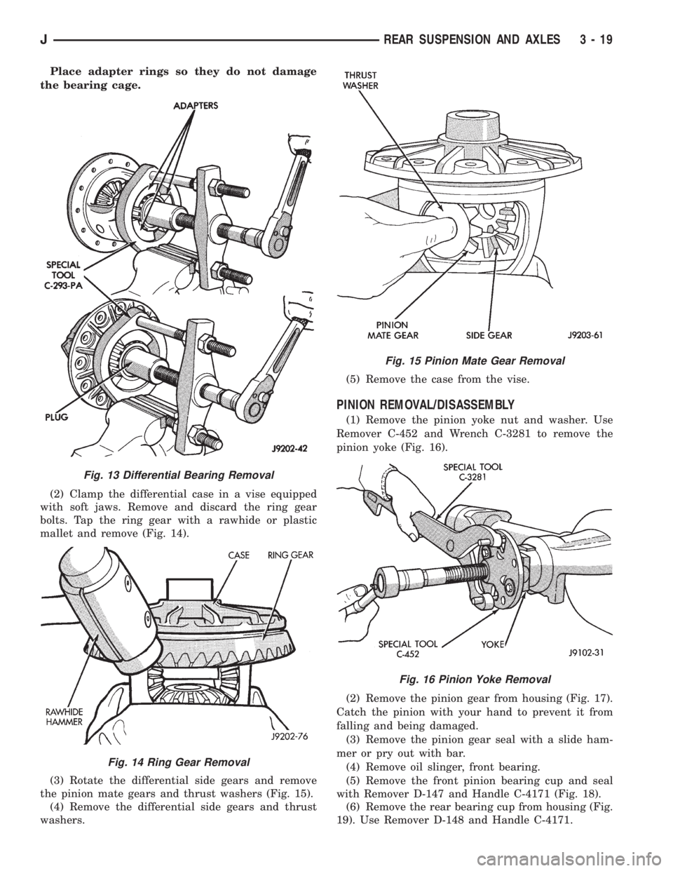
(2) Clamp the differential case in a vise equipped
with soft jaws. Remove and discard the ring gear
bolts. Tap the ring gear with a rawhide or plastic
mallet and remove (Fig. 14).
(3) Rotate the differential side gears and remove
the pinion mate gears and thrust washers (Fig. 15).
(4) Remove the differential side gears and thrust
washers.(5) Remove the case from the vise.
PINION REMOVAL/DISASSEMBLY
(1) Remove the pinion yoke nut and washer. Use
Remover C-452 and Wrench C-3281 to remove the
pinion yoke (Fig. 16).
(2) Remove the pinion gear from housing (Fig. 17).
Catch the pinion with your hand to prevent it from
falling and being damaged.
(3) Remove the pinion gear seal with a slide ham-
mer or pry out with bar.
(4) Remove oil slinger, front bearing.
(5) Remove the front pinion bearing cup and seal
with Remover D-147 and Handle C-4171 (Fig. 18).
(6) Remove the rear bearing cup from housing (Fig.
19). Use Remover D-148 and Handle C-4171.
Fig. 13 Differential Bearing Removal
Fig. 14 Ring Gear Removal
Fig. 15 Pinion Mate Gear Removal
Fig. 16 Pinion Yoke Removal
JREAR SUSPENSION AND AXLES 3 - 19
Page 105 of 2198
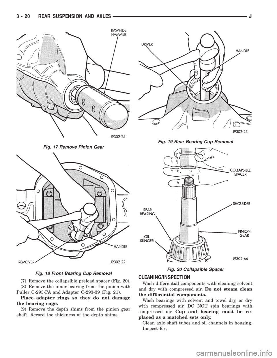
(7) Remove the collapsible preload spacer (Fig. 20).
(8) Remove the inner bearing from the pinion with
Puller C-293-PA and Adapter C-293-39 (Fig. 21).
Place adapter rings so they do not damage
the bearing cage.
(9) Remove the depth shims from the pinion gear
shaft. Record the thickness of the depth shims.CLEANING/INSPECTION
Wash differential components with cleaning solvent
and dry with compressed air.Do not steam clean
the differential components.
Wash bearings with solvent and towel dry, or dry
with compressed air. DO NOT spin bearings with
compressed airCup and bearing must be re-
placed as a matched sets only.
Clean axle shaft tubes and oil channels in housing.
Inspect for;
Fig. 17 Remove Pinion Gear
Fig. 18 Front Bearing Cup Removal
Fig. 19 Rear Bearing Cup Removal
Fig. 20 Collapsible Spacer
3 - 20 REAR SUSPENSION AND AXLESJ
Page 106 of 2198
²Smooth appearance with no broken/dented sur-
faces on the bearing rollers or the roller contact sur-
faces
²Bearing cups must not be distorted or cracked
²Machined surfaces should be smooth and without
any raised edges
²Raised metal on shoulders of cup bores should be
removed with a hand stone
²Wear and damage to pinion gear mate shaft, pin-
ion gears, side gears and thrust washers. Replace as
a matched set only.
²Ring and pinion gear for worn and chipped teeth
²Ring gear for damaged bolt threads. Replaced as a
matched set only.
²Pinion yoke for cracks, worn splines, pitted areas,
and a rough/corroded seal contact surface. Repair or
replace as necessary.
²Preload shims for damage and distortion. Install
new shims if necessary.
DIFFERENTIAL ASSEMBLY
(1) Install the following components in the differ-
ential case.
²Differential side gears and thrust washers
²Pinion gears and thrust washers
²Pinion gear mate shaft (align holes in shaft and
case)
(2) Lubricate all differential components with hy-
poid gear lubricant.
PINION GEAR DEPTH INFORMATION
Ring and pinion gears are supplied as matched sets
only. The identifying numbers for the ring and pinion
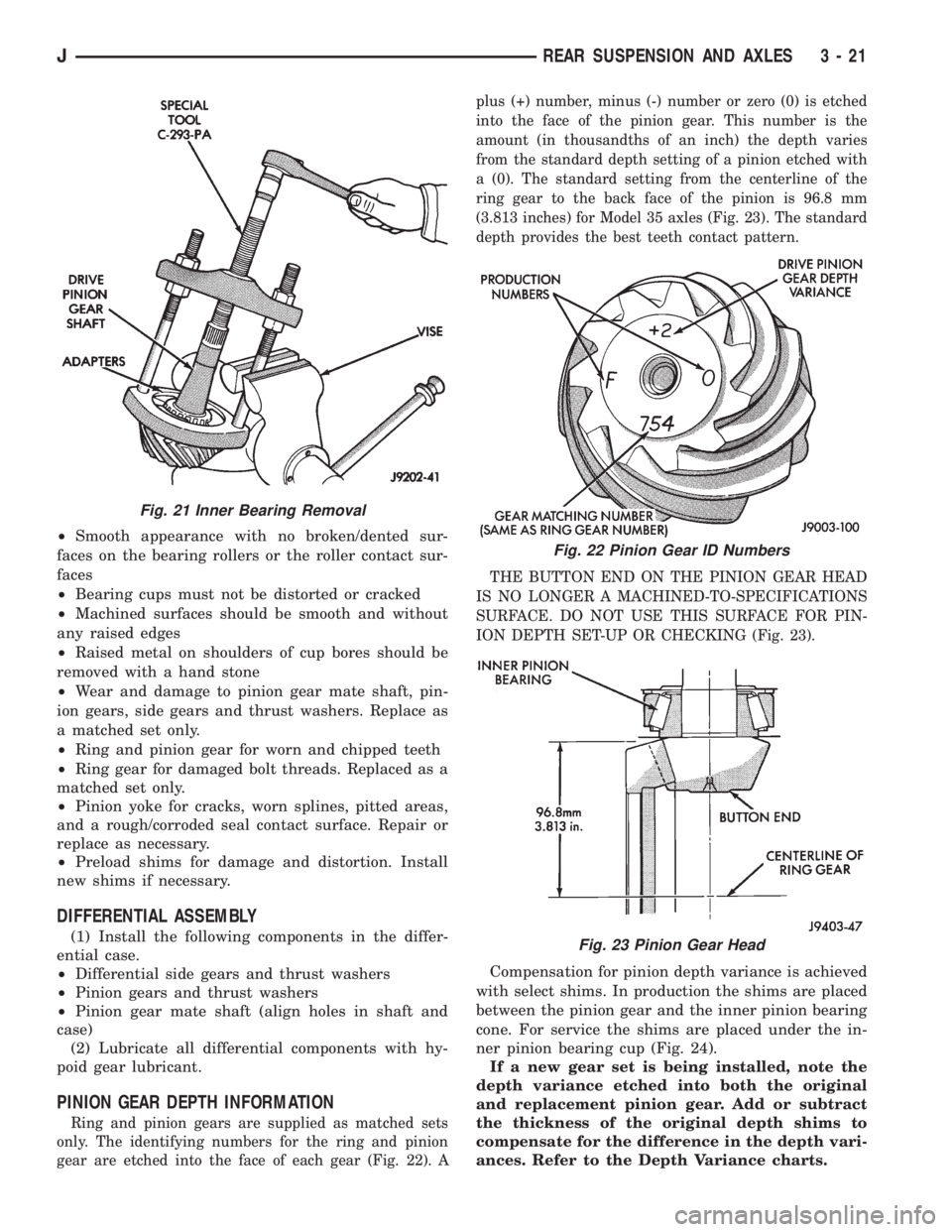
gear are etched into the face of each gear (Fig. 22). Aplus (+) number, minus (-) number or zero (0) is etched
into the face of the pinion gear. This number is the
amount (in thousandths of an inch) the depth varies
from the standard depth setting of a pinion etched with
a (0). The standard setting from the centerline of the
ring gear to the back face of the pinion is 96.8 mm
(3.813 inches) for Model 35 axles (Fig. 23). The standard
depth provides the best teeth contact pattern.
THE BUTTON END ON THE PINION GEAR HEAD
IS NO LONGER A MACHINED-TO-SPECIFICATIONS
SURFACE. DO NOT USE THIS SURFACE FOR PIN-
ION DEPTH SET-UP OR CHECKING (Fig. 23).
Compensation for pinion depth variance is achieved
with select shims. In production the shims are placed
between the pinion gear and the inner pinion bearing
cone. For service the shims are placed under the in-
ner pinion bearing cup (Fig. 24).
If a new gear set is being installed, note the
depth variance etched into both the original
and replacement pinion gear. Add or subtract
the thickness of the original depth shims to
compensate for the difference in the depth vari-
ances. Refer to the Depth Variance charts.
Fig. 21 Inner Bearing Removal
Fig. 22 Pinion Gear ID Numbers
Fig. 23 Pinion Gear Head
JREAR SUSPENSION AND AXLES 3 - 21
Page 107 of 2198
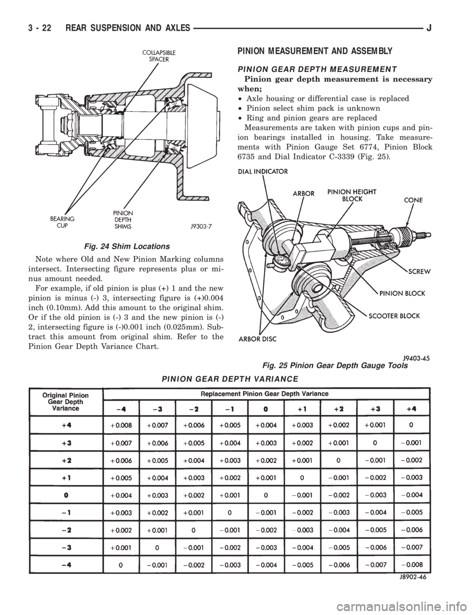
Note where Old and New Pinion Marking columns
intersect. Intersecting figure represents plus or mi-
nus amount needed.
For example, if old pinion is plus (+) 1 and the new
pinion is minus (-) 3, intersecting figure is (+)0.004
inch (0.10mm). Add this amount to the original shim.
Or if the old pinion is (-) 3 and the new pinion is (-)
2, intersecting figure is (-)0.001 inch (0.025mm). Sub-
tract this amount from original shim. Refer to the
Pinion Gear Depth Variance Chart.
PINION MEASUREMENT AND ASSEMBLY
PINION GEAR DEPTH MEASUREMENT
Pinion gear depth measurement is necessary
when;
²Axle housing or differential case is replaced
²Pinion select shim pack is unknown
²Ring and pinion gears are replaced
Measurements are taken with pinion cups and pin-
ion bearings installed in housing. Take measure-
ments with Pinion Gauge Set 6774, Pinion Block
6735 and Dial Indicator C-3339 (Fig. 25).
Fig. 24 Shim Locations
PINION GEAR DEPTH VARIANCE
Fig. 25 Pinion Gear Depth Gauge Tools
3 - 22 REAR SUSPENSION AND AXLESJ
Page 108 of 2198
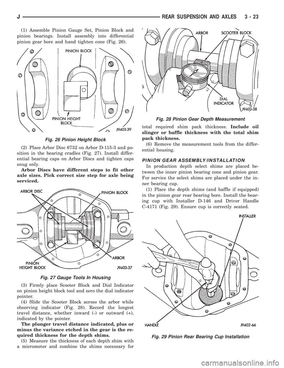
(1) Assemble Pinion Gauge Set, Pinion Block and
pinion bearings. Install assembly into differential
pinion gear bore and hand tighten cone (Fig. 26).
(2) Place Arbor Disc 6732 on Arbor D-115-3 and po-
sition in the bearing cradles (Fig. 27). Install differ-
ential bearing caps on Arbor Discs and tighten caps
snug only.
Arbor Discs have different steps to fit other
axle sizes. Pick correct size step for axle being
serviced.
(3) Firmly place Scooter Block and Dial Indicator
on pinion height block tool and zero the dial indicator
pointer.
(4) Slide the Scooter Block across the arbor while
observing indicator (Fig. 28). Record the longest
travel distance, whether inward (-) or outward (+),
indicated by the pointer.
The plunger travel distance indicated, plus or
minus the variance etched in the gear is the re-
quired thickness for the depth shims.
(5) Measure the thickness of each depth shim with
a micrometer and combine the shims necessary fortotal required shim pack thickness.Include oil
slinger or baffle thickness with the total shim
pack thickness.
(6) Remove the measurement tools from the differ-
ential housing.
PINION GEAR ASSEMBLY/INSTALLATION
In production depth select shims are placed be-
tween the inner pinion bearing cone and pinion gear.
For service the select shims are placed under the in-
ner bearing cup.
(1) Place the depth shims (and baffle if equipped)
in the pinion gear rear bearing bore. Install the bear-
ing cup with Installer D-146 and Driver Handle
C-4171 (Fig. 29). Ensure cup is correctly seated.
Fig. 26 Pinion Height Block
Fig. 27 Gauge Tools In Housing
Fig. 28 Pinion Gear Depth Measurement
Fig. 29 Pinion Rear Bearing Cup Installation
JREAR SUSPENSION AND AXLES 3 - 23
Page 109 of 2198
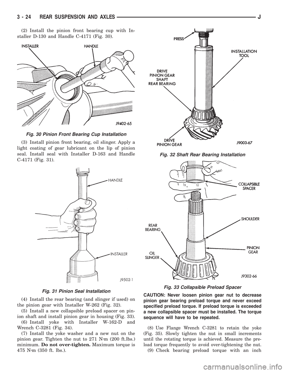
(2) Install the pinion front bearing cup with In-
staller D-130 and Handle C-4171 (Fig. 30).
(3) Install pinion front bearing, oil slinger. Apply a
light coating of gear lubricant on the lip of pinion
seal. Install seal with Installer D-163 and Handle
C-4171 (Fig. 31).
(4) Install the rear bearing (and slinger if used) on
the pinion gear with Installer W-262 (Fig. 32).
(5) Install a new collapsible preload spacer on pin-
ion shaft and install pinion gear in housing (Fig. 33).
(6) Install yoke with Installer W-162-D and
Wrench C-3281 (Fig. 34).
(7) Install the yoke washer and a new nut on the
pinion gear. Tighten the nut to 271 Nzm (200 ft.lbs.)
minimum.Do not over-tighten.Maximum torque is
475 Nzm (350 ft. lbs.).
CAUTION: Never loosen pinion gear nut to decrease
pinion gear bearing preload torque and never exceed
specified preload torque. If preload torque is exceeded
a new collapsible spacer must be installed. The torque
sequence will have to be repeated.
(8) Use Flange Wrench C-3281 to retain the yoke
(Fig. 35). Slowly tighten the nut in small increments
until the rotating torque is achieved. Measure the pre-
load torque frequently to avoid over-tightening the nut.
(9) Check bearing preload torque with an inch
Fig. 30 Pinion Front Bearing Cup Installation
Fig. 31 Pinion Seal Installation
Fig. 32 Shaft Rear Bearing Installation
Fig. 33 Collapsible Preload Spacer
3 - 24 REAR SUSPENSION AND AXLESJ
Page 110 of 2198
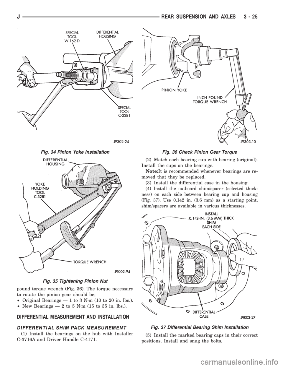
pound torque wrench (Fig. 36). The torque necessary
to rotate the pinion gear should be;
²Original Bearings Ð 1 to 3 Nzm (10 to 20 in. lbs.).
²New BearingsÐ2to5Nzm (15 to 35 in. lbs.).
DIFFERENTIAL MEASUREMENT AND INSTALLATION
DIFFERENTIAL SHIM PACK MEASUREMENT
(1) Install the bearings on the hub with Installer
C-3716A and Driver Handle C-4171.(2) Match each bearing cup with bearing (original).
Install the cups on the bearings.
Note:It is recommended whenever bearings are re-
moved that they be replaced.
(3) Install the differential case in the housing.
(4) Install the outboard shim/spacer (selected thick-
ness) on each side between bearing cup and housing
(Fig. 37). Use 0.142 in. (3.6 mm) as a starting point,
shim/spacers are available in various thicknesses.
(5) Install the marked bearing caps in their correct
positions. Install and snug the bolts.
Fig. 34 Pinion Yoke Installation
Fig. 35 Tightening Pinion Nut
Fig. 36 Check Pinion Gear Torque
Fig. 37 Differential Bearing Shim Installation
JREAR SUSPENSION AND AXLES 3 - 25