JEEP CHEROKEE 1995 Service Repair Manual
Manufacturer: JEEP, Model Year: 1995, Model line: CHEROKEE, Model: JEEP CHEROKEE 1995Pages: 2198, PDF Size: 82.83 MB
Page 121 of 2198
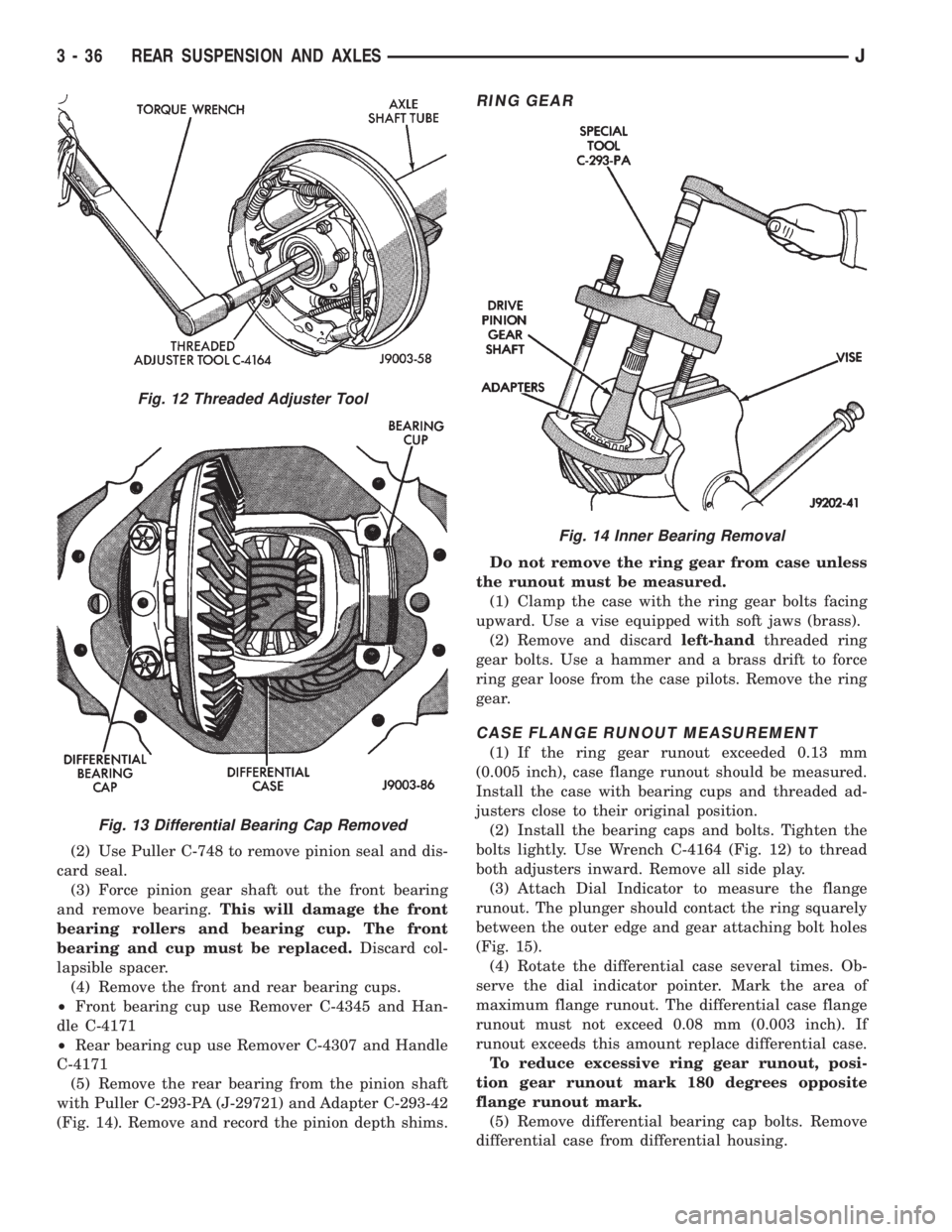
(2) Use Puller C-748 to remove pinion seal and dis-
card seal.
(3) Force pinion gear shaft out the front bearing
and remove bearing.This will damage the front
bearing rollers and bearing cup. The front
bearing and cup must be replaced.Discard col-
lapsible spacer.
(4) Remove the front and rear bearing cups.
²Front bearing cup use Remover C-4345 and Han-
dle C-4171
²Rear bearing cup use Remover C-4307 and Handle
C-4171
(5) Remove the rear bearing from the pinion shaft
with Puller C-293-PA (J-29721) and Adapter C-293-42
(Fig. 14). Remove and record the pinion depth shims.
RING GEAR
Do not remove the ring gear from case unless
the runout must be measured.
(1) Clamp the case with the ring gear bolts facing
upward. Use a vise equipped with soft jaws (brass).
(2) Remove and discardleft-handthreaded ring
gear bolts. Use a hammer and a brass drift to force
ring gear loose from the case pilots. Remove the ring
gear.
CASE FLANGE RUNOUT MEASUREMENT
(1) If the ring gear runout exceeded 0.13 mm
(0.005 inch), case flange runout should be measured.
Install the case with bearing cups and threaded ad-
justers close to their original position.
(2) Install the bearing caps and bolts. Tighten the
bolts lightly. Use Wrench C-4164 (Fig. 12) to thread
both adjusters inward. Remove all side play.
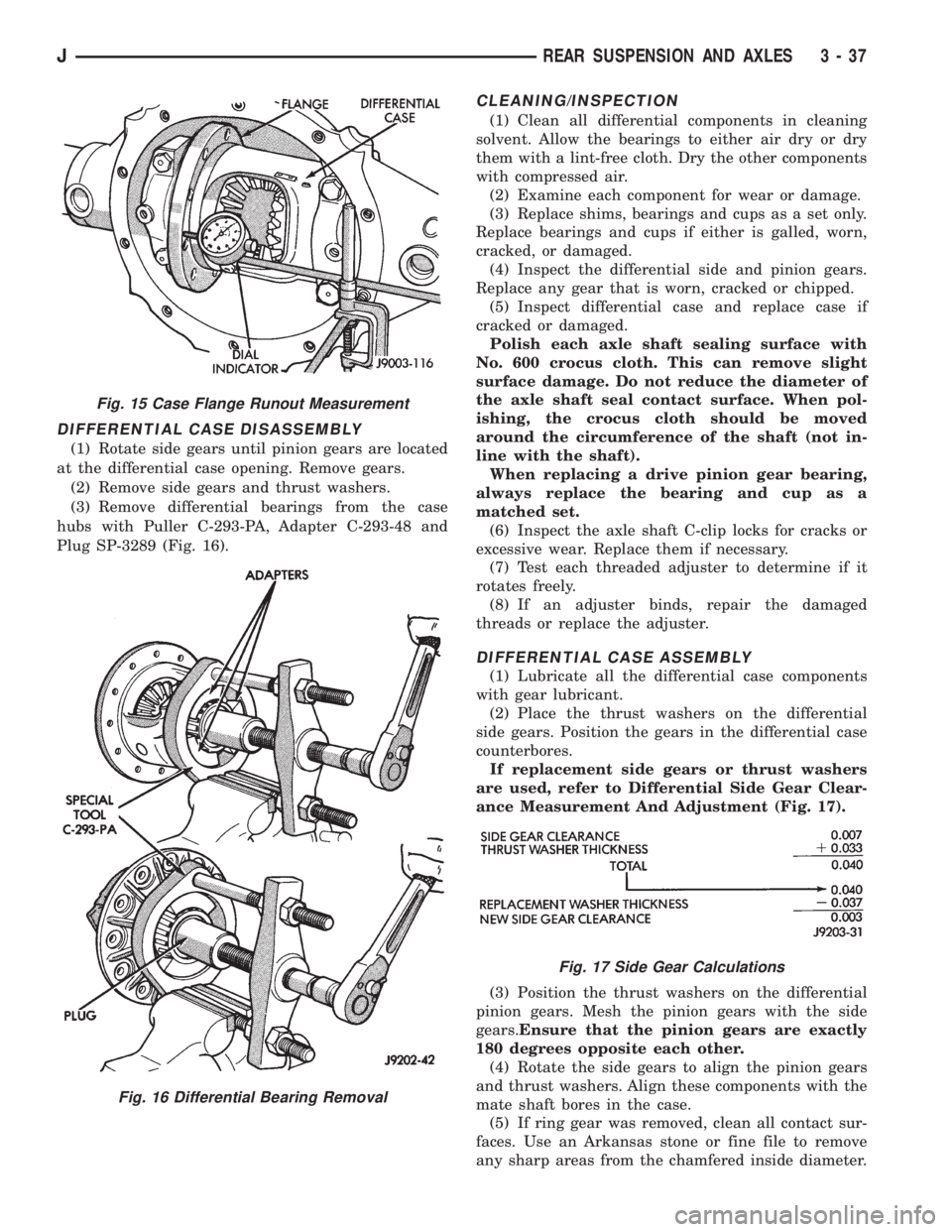
(3) Attach Dial Indicator to measure the flange
runout. The plunger should contact the ring squarely
between the outer edge and gear attaching bolt holes
(Fig. 15).
(4) Rotate the differential case several times. Ob-
serve the dial indicator pointer. Mark the area of
maximum flange runout. The differential case flange
runout must not exceed 0.08 mm (0.003 inch). If
runout exceeds this amount replace differential case.
To reduce excessive ring gear runout, posi-
tion gear runout mark 180 degrees opposite
flange runout mark.
(5) Remove differential bearing cap bolts. Remove
differential case from differential housing.
Fig. 12 Threaded Adjuster Tool
Fig. 13 Differential Bearing Cap Removed
Fig. 14 Inner Bearing Removal
3 - 36 REAR SUSPENSION AND AXLESJ
Page 122 of 2198
DIFFERENTIAL CASE DISASSEMBLY
(1) Rotate side gears until pinion gears are located
at the differential case opening. Remove gears.
(2) Remove side gears and thrust washers.
(3) Remove differential bearings from the case
hubs with Puller C-293-PA, Adapter C-293-48 and
Plug SP-3289 (Fig. 16).
CLEANING/INSPECTION
(1) Clean all differential components in cleaning
solvent. Allow the bearings to either air dry or dry
them with a lint-free cloth. Dry the other components
with compressed air.
(2) Examine each component for wear or damage.
(3) Replace shims, bearings and cups as a set only.
Replace bearings and cups if either is galled, worn,
cracked, or damaged.
(4) Inspect the differential side and pinion gears.
Replace any gear that is worn, cracked or chipped.
(5) Inspect differential case and replace case if
cracked or damaged.
Polish each axle shaft sealing surface with
No. 600 crocus cloth. This can remove slight
surface damage. Do not reduce the diameter of
the axle shaft seal contact surface. When pol-
ishing, the crocus cloth should be moved
around the circumference of the shaft (not in-
line with the shaft).
When replacing a drive pinion gear bearing,
always replace the bearing and cup as a
matched set.
(6) Inspect the axle shaft C-clip locks for cracks or
excessive wear. Replace them if necessary.
(7) Test each threaded adjuster to determine if it
rotates freely.
(8) If an adjuster binds, repair the damaged
threads or replace the adjuster.
DIFFERENTIAL CASE ASSEMBLY
(1) Lubricate all the differential case components
with gear lubricant.
(2) Place the thrust washers on the differential
side gears. Position the gears in the differential case
counterbores.
If replacement side gears or thrust washers
are used, refer to Differential Side Gear Clear-
ance Measurement And Adjustment (Fig. 17).
(3) Position the thrust washers on the differential
pinion gears. Mesh the pinion gears with the side
gears.Ensure that the pinion gears are exactly
180 degrees opposite each other.
(4) Rotate the side gears to align the pinion gears
and thrust washers. Align these components with the
mate shaft bores in the case.
(5) If ring gear was removed, clean all contact sur-
faces. Use an Arkansas stone or fine file to remove
any sharp areas from the chamfered inside diameter.
Fig. 15 Case Flange Runout Measurement
Fig. 16 Differential Bearing Removal
Fig. 17 Side Gear Calculations
JREAR SUSPENSION AND AXLES 3 - 37
Page 123 of 2198
(6) If removed, heat ring gear with a heat lamp or
by immersing in a hot fluid. The temperature should
not exceed 149ÉC (300ÉF).Do not use a torch to
heat the ring gear.
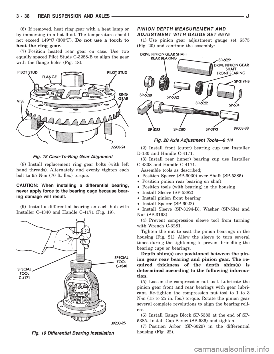
(7) Position heated rear gear on case. Use two
equally spaced Pilot Studs C-3288-B to align the gear
with the flange holes (Fig. 18).
(8) Install replacement ring gear bolts (with left
hand threads). Alternately and evenly tighten each
bolt to 95 Nzm (70 ft. lbs.) torque.
CAUTION: When installing a differential bearing,
never apply force to the bearing cage because bear-
ing damage will result.
(9) Install a differential bearing on each hub with
Installer C-4340 and Handle C-4171 (Fig. 19).PINION DEPTH MEASUREMENT AND
ADJUSTMENT WITH GAUGE SET 6575
(1) Use pinion gear adjustment gauge set 6575
(Fig. 20) and continue the assembly:
(2) Install front (outer) bearing cup use Installer
D-130 and Handle C-4171.
(3) Install rear (inner) bearing cup use Installer
C-4308 and Handle C-4171.
Assemble tools as described;
²Position Spacer (SP-6030) over Shaft (SP-5385)
²Position pinion rear bearing on shaft
²Position tools (with bearing) in the housing
²Install Sleeve (SP-5382)
²Install pinion front bearing
²Install Spacer (SP-6022)
²Install Sleeve (SP-3194-B), Washer (SP-534) and
Nut (SP-3193)
(4) Prevent compression sleeve tool from turning
with Wrench C-3281.
Tighten the nut to seat the pinion bearings in the
housing (Fig. 21). Allow the sleeve to turn several
times during the tightening to prevent brinelling the
bearing cups or bearings.
Depth shim(s) are positioned between the pin-
ion gear rear bearing and pinion gear. The re-
quired thickness of the depth shim(s) is
determined according to the following informa-
tion.
(5) Loosen the compression nut tool. Lubricate the
pinion gear front and rear bearings with gear lubri-
cant. Re-tighten the compression nut tool to 1 to 3
Nzm (15 to 25 in. lbs.) torque. Rotate the pinion gear
several complete revolutions to align the bearing roll-
ers.
(6) Install Gauge Block SP-5383 at the end of SP-
5385. Install Cap Screw (SP-536) and tighten.
(7) Position Arbor (SP-6029) in the differential
housing (Fig. 22).
Fig. 18 Case-To-Ring Gear Alignment
Fig. 19 Differential Bearing Installation
Fig. 20 Axle Adjustment ToolsÐ8 1/4
3 - 38 REAR SUSPENSION AND AXLESJ
Page 124 of 2198
(8) Center the tool. Place a piece of 0.002 inch
shim stock at each end of the arbor tool. Install the
bearing caps on the arbor tool. Tighten the cap bolts
to 14 Nzm (10 ft. lbs.) torque.
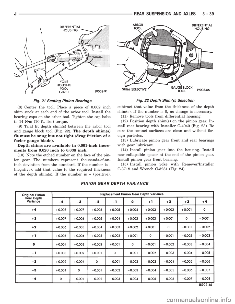
(9) Trial fit depth shim(s) between the arbor tool
and gauge block tool (Fig. 22).The depth shim(s)
fit must be snug but not tight (drag friction of a
feeler gauge blade).
Depth shims are available in 0.001-inch incre-
ments from 0.020 inch to 0.038 inch.
(10) Note the etched number on the face of the pin-
ion gear. The numbers represent thousands-of-an-
inch deviation from the standard. If the number is -
(negative), add that value to the required thickness
of the depth shim(s). If the number is + (positive),subtract that value from the thickness of the depth
shim(s). If the number is 0, no change is necessary.
(11) Remove tools from differential housing.
(12) Position depth shim(s) on the pinion gear. In-
stall rear bearing with Installer C-4040 (Fig. 23). Be
sure the contact surfaces are clean and without for-
eign particles.
(13) Lubricate pinion gear front and rear bearings
with gear lubricant.
(14) Install pinion gear into the housing. Install
new collapsible spacer at the end of the pinion gear.
Install pinion gear front bearing.
(15) Install pinion yoke with Remover/Installer
C-3718 and Wrench C-3281 (Fig. 24).
Fig. 22 Depth Shim(s) Selection
PINION GEAR DEPTH VARIANCE
Fig. 21 Seating Pinion Bearings
JREAR SUSPENSION AND AXLES 3 - 39
Page 125 of 2198
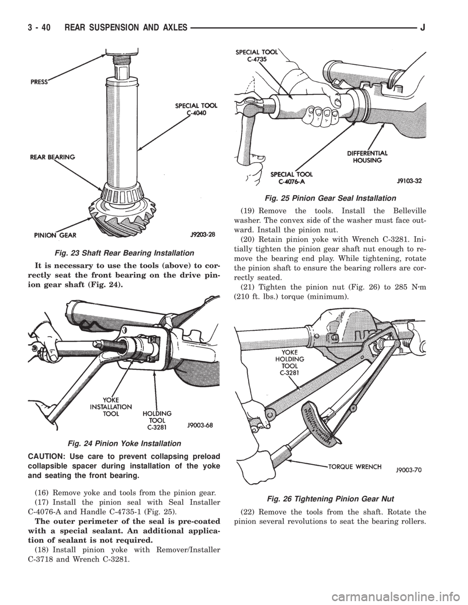
It is necessary to use the tools (above) to cor-
rectly seat the front bearing on the drive pin-
ion gear shaft (Fig. 24).
CAUTION: Use care to prevent collapsing preload
collapsible spacer during installation of the yoke
and seating the front bearing.
(16) Remove yoke and tools from the pinion gear.
(17) Install the pinion seal with Seal Installer
C-4076-A and Handle C-4735-1 (Fig. 25).
The outer perimeter of the seal is pre-coated
with a special sealant. An additional applica-
tion of sealant is not required.
(18) Install pinion yoke with Remover/Installer
C-3718 and Wrench C-3281.(19) Remove the tools. Install the Belleville
washer. The convex side of the washer must face out-
ward. Install the pinion nut.
(20) Retain pinion yoke with Wrench C-3281. Ini-
tially tighten the pinion gear shaft nut enough to re-
move the bearing end play. While tightening, rotate
the pinion shaft to ensure the bearing rollers are cor-
rectly seated.
(21) Tighten the pinion nut (Fig. 26) to 285 Nzm
(210 ft. lbs.) torque (minimum).
(22) Remove the tools from the shaft. Rotate the
pinion several revolutions to seat the bearing rollers.
Fig. 23 Shaft Rear Bearing Installation
Fig. 24 Pinion Yoke Installation
Fig. 25 Pinion Gear Seal Installation
Fig. 26 Tightening Pinion Gear Nut
3 - 40 REAR SUSPENSION AND AXLESJ
Page 126 of 2198
CAUTION: Never loosen pinion gear nut to decrease
pinion gear bearing preload torque and never ex-
ceed specified preload torque. If preload torque is
exceeded a new collapsible spacer must be in-
stalled. The torque sequence will have to be re-
peated.
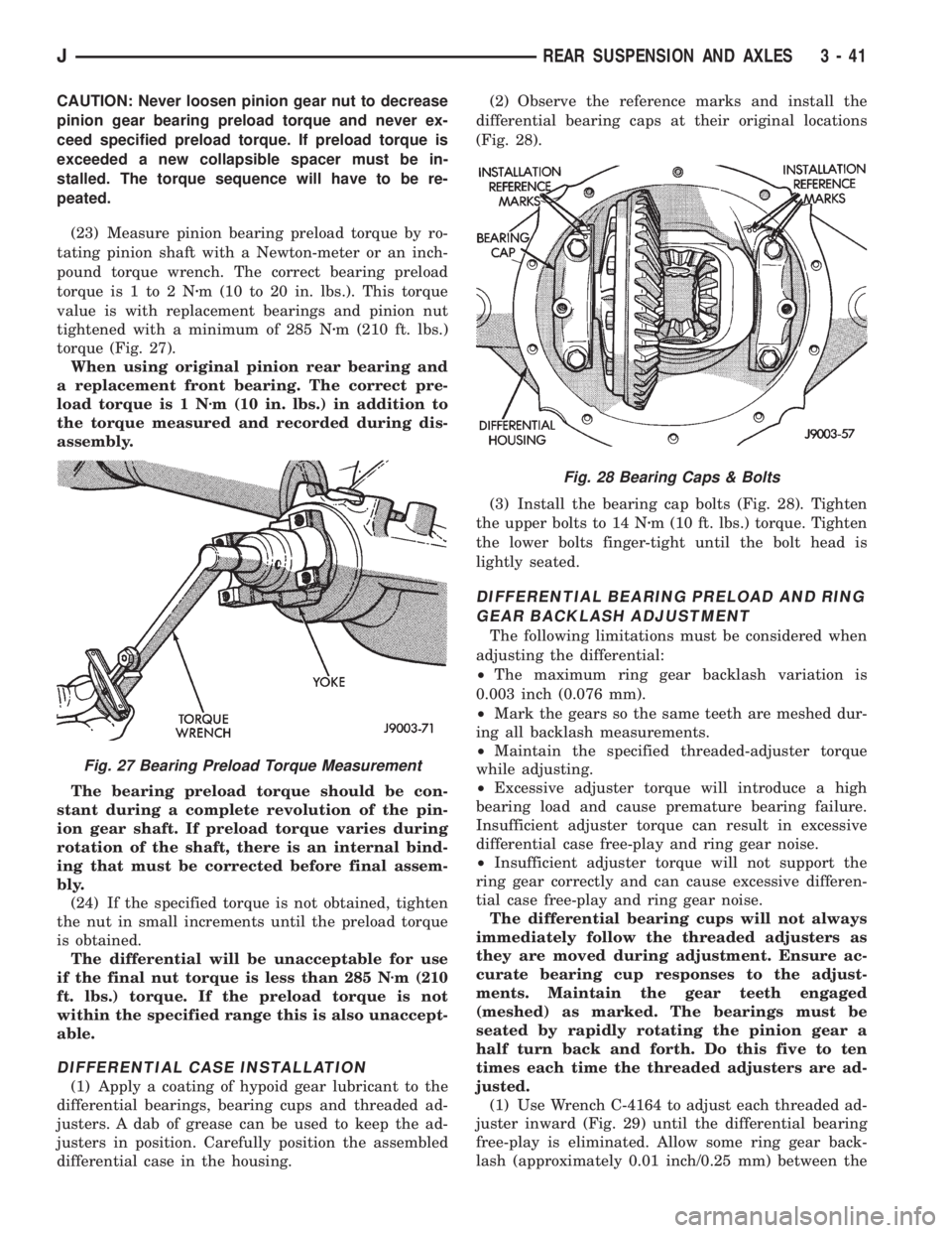
(23) Measure pinion bearing preload torque by ro-
tating pinion shaft with a Newton-meter or an inch-
pound torque wrench. The correct bearing preload
torque is 1 to 2 Nzm (10 to 20 in. lbs.). This torque
value is with replacement bearings and pinion nut
tightened with a minimum of 285 Nzm (210 ft. lbs.)
torque (Fig. 27).
When using original pinion rear bearing and
a replacement front bearing. The correct pre-
load torque is 1 Nzm (10 in. lbs.) in addition to
the torque measured and recorded during dis-
assembly.
The bearing preload torque should be con-
stant during a complete revolution of the pin-
ion gear shaft. If preload torque varies during
rotation of the shaft, there is an internal bind-
ing that must be corrected before final assem-
bly.
(24) If the specified torque is not obtained, tighten
the nut in small increments until the preload torque
is obtained.
The differential will be unacceptable for use
if the final nut torque is less than 285 Nzm (210
ft. lbs.) torque. If the preload torque is not
within the specified range this is also unaccept-
able.
DIFFERENTIAL CASE INSTALLATION
(1) Apply a coating of hypoid gear lubricant to the
differential bearings, bearing cups and threaded ad-
justers. A dab of grease can be used to keep the ad-
justers in position. Carefully position the assembled
differential case in the housing.(2) Observe the reference marks and install the
differential bearing caps at their original locations
(Fig. 28).
(3) Install the bearing cap bolts (Fig. 28). Tighten
the upper bolts to 14 Nzm (10 ft. lbs.) torque. Tighten
the lower bolts finger-tight until the bolt head is
lightly seated.
DIFFERENTIAL BEARING PRELOAD AND RING
GEAR BACKLASH ADJUSTMENT
The following limitations must be considered when
adjusting the differential:
²The maximum ring gear backlash variation is
0.003 inch (0.076 mm).
²Mark the gears so the same teeth are meshed dur-
ing all backlash measurements.
²Maintain the specified threaded-adjuster torque
while adjusting.
²Excessive adjuster torque will introduce a high
bearing load and cause premature bearing failure.
Insufficient adjuster torque can result in excessive
differential case free-play and ring gear noise.
²Insufficient adjuster torque will not support the
ring gear correctly and can cause excessive differen-
tial case free-play and ring gear noise.
The differential bearing cups will not always
immediately follow the threaded adjusters as
they are moved during adjustment. Ensure ac-
curate bearing cup responses to the adjust-
ments. Maintain the gear teeth engaged
(meshed) as marked. The bearings must be
seated by rapidly rotating the pinion gear a
half turn back and forth. Do this five to ten
times each time the threaded adjusters are ad-
justed.
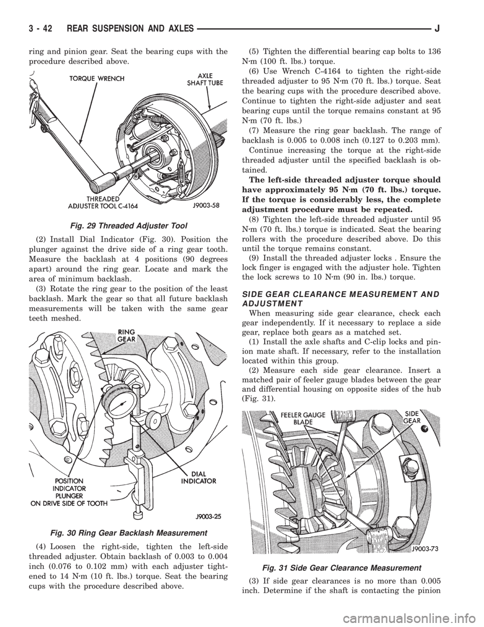
(1) Use Wrench C-4164 to adjust each threaded ad-
juster inward (Fig. 29) until the differential bearing
free-play is eliminated. Allow some ring gear back-
lash (approximately 0.01 inch/0.25 mm) between the
Fig. 27 Bearing Preload Torque Measurement
Fig. 28 Bearing Caps & Bolts
JREAR SUSPENSION AND AXLES 3 - 41
Page 127 of 2198
ring and pinion gear. Seat the bearing cups with the
procedure described above.
(2) Install Dial Indicator (Fig. 30). Position the
plunger against the drive side of a ring gear tooth.
Measure the backlash at 4 positions (90 degrees
apart) around the ring gear. Locate and mark the
area of minimum backlash.
(3) Rotate the ring gear to the position of the least
backlash. Mark the gear so that all future backlash
measurements will be taken with the same gear
teeth meshed.
(4) Loosen the right-side, tighten the left-side
threaded adjuster. Obtain backlash of 0.003 to 0.004
inch (0.076 to 0.102 mm) with each adjuster tight-
ened to 14 Nzm (10 ft. lbs.) torque. Seat the bearing
cups with the procedure described above.(5) Tighten the differential bearing cap bolts to 136
Nzm (100 ft. lbs.) torque.
(6) Use Wrench C-4164 to tighten the right-side
threaded adjuster to 95 Nzm (70 ft. lbs.) torque. Seat
the bearing cups with the procedure described above.
Continue to tighten the right-side adjuster and seat
bearing cups until the torque remains constant at 95
Nzm (70 ft. lbs.)
(7) Measure the ring gear backlash. The range of
backlash is 0.005 to 0.008 inch (0.127 to 0.203 mm).
Continue increasing the torque at the right-side
threaded adjuster until the specified backlash is ob-
tained.
The left-side threaded adjuster torque should
have approximately 95 Nzm (70 ft. lbs.) torque.
If the torque is considerably less, the complete
adjustment procedure must be repeated.
(8) Tighten the left-side threaded adjuster until 95
Nzm (70 ft. lbs.) torque is indicated. Seat the bearing
rollers with the procedure described above. Do this
until the torque remains constant.
(9) Install the threaded adjuster locks . Ensure the
lock finger is engaged with the adjuster hole. Tighten
the lock screws to 10 Nzm (90 in. lbs.) torque.
SIDE GEAR CLEARANCE MEASUREMENT AND
ADJUSTMENT
When measuring side gear clearance, check each
gear independently. If it necessary to replace a side
gear, replace both gears as a matched set.
(1) Install the axle shafts and C-clip locks and pin-
ion mate shaft. If necessary, refer to the installation
located within this group.
(2) Measure each side gear clearance. Insert a
matched pair of feeler gauge blades between the gear
and differential housing on opposite sides of the hub
(Fig. 31).
(3) If side gear clearances is no more than 0.005
inch. Determine if the shaft is contacting the pinion
Fig. 29 Threaded Adjuster Tool
Fig. 30 Ring Gear Backlash Measurement
Fig. 31 Side Gear Clearance Measurement
3 - 42 REAR SUSPENSION AND AXLESJ
Page 128 of 2198
gear mate shaft.Do not remove the feeler
gauges, inspect the axle shaft with the feeler
gauge inserted behind the side gear.If the end of
the axle shaft is not contacting the pinion gear mate
shaft, the side gear clearance is acceptable.
(4) If clearance is more than 0.005 inch (axle shaft
not contacting mate shaft), record the side gear clear-
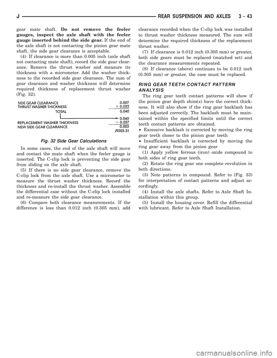
ance. Remove the thrust washer and measure its
thickness with a micrometer. Add the washer thick-
ness to the recorded side gear clearance. The sum of
gear clearance and washer thickness will determine
required thickness of replacement thrust washer
(Fig. 32).
In some cases, the end of the axle shaft will move
and contact the mate shaft when the feeler gauge is
inserted. The C-clip lock is preventing the side gear
from sliding on the axle shaft.
(5) If there is no side gear clearance, remove the
C-clip lock from the axle shaft. Use a micrometer to
measure the thrust washer thickness. Record the
thickness and re-install the thrust washer. Assemble
the differential case without the C-clip lock installed
and re-measure the side gear clearance.
(6) Compare both clearance measurements. If the
difference is less than 0.012 inch (0.305 mm), addclearance recorded when the C-clip lock was installed
to thrust washer thickness measured. The sum will
determine the required thickness of the replacement
thrust washer.
(7) If clearance is 0.012 inch (0.305 mm) or greater,
both side gears must be replaced (matched set) and
the clearance measurements repeated.
(8) If clearance (above) continues to be 0.012 inch
(0.305 mm) or greater, the case must be replaced.
RING GEAR TEETH CONTACT PATTERN
ANALYSIS
The ring gear teeth contact patterns will show if
the pinion gear depth shim(s) have the correct thick-
ness. It will also show if the ring gear backlash has
been adjusted correctly. The backlash must be main-
tained within the specified limits until the correct
teeth contact patterns are obtained.
²Excessive backlash is corrected by moving the ring
gear teeth closer to the pinion gear teeth
²Insufficient backlash is corrected by moving the
ring gear away from the pinion gear
(1) Apply yellow ferrous (iron) oxide compound to
both sides of ring gear teeth.
(2) Rotate the ring gear one complete revolution in
both directions.
(3) Note patterns in compound. Refer to (Fig. 33)
for interpretation of contact patterns and adjust ac-
cordingly.
(4) Install the axle shafts. Refer to Axle Shaft In-
stallation within this group.
(5) Install the housing cover. Refill the differential
with lubricant. Refer to Axle Shaft Installation.
Fig. 32 Side Gear Calculations
JREAR SUSPENSION AND AXLES 3 - 43
Page 129 of 2198
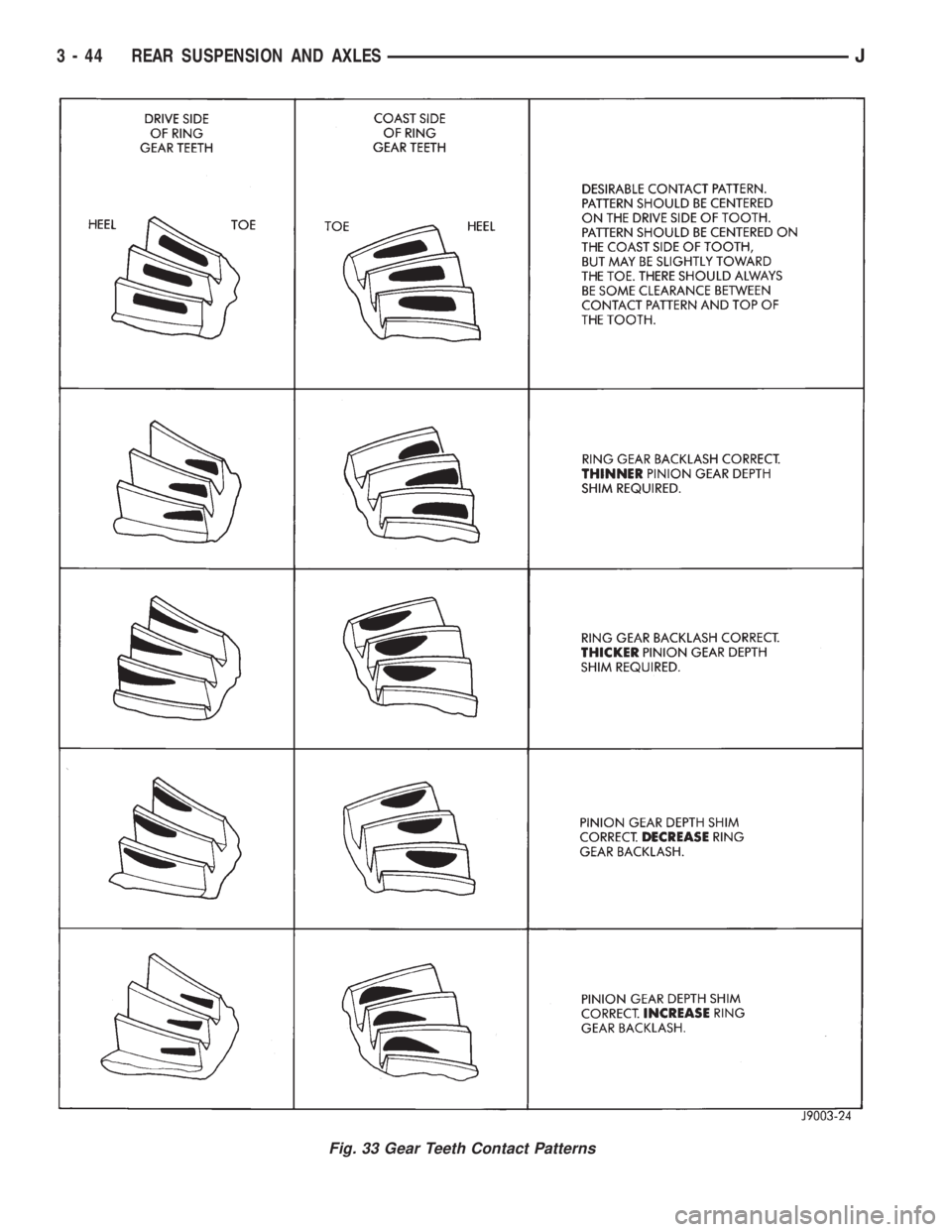
Fig. 33 Gear Teeth Contact Patterns
3 - 44 REAR SUSPENSION AND AXLESJ
Page 130 of 2198

TRAC-LOK DIFFERENTIAL
OPERATION
In a conventional differential, the torque applied to
the ring gear is transmitted to the axle shafts through
the differential gears. During normal operation, the
torque transmitted to each wheel is equal at all times.
However, if one wheel spins, the opposite wheel will
generate only as much torque as the spinning wheel.
In the Trac-Lok differential, part of the ring gear
torque is transmitted through clutch packs. The clutch
packs contain multiple disc. The clutch will have radial
grooves on the plates, and concentric grooves on the
discs or bonded fiber material which is smooth.
In operation, the Trac-Lok clutches are engaged by
two concurrent forces. The first being preload force ex-
erted through Belleville spring washers. The second is
from separating forces generated by the side gears (Fig.
1).
The Trac-Lok design provides the normal differential
action needed for turning corners. It also provides for
the transmission of equal torque to both wheels when
driving straight ahead. When one wheel loses traction,
the clutch packs transfer torque to the wheel having the
most traction. Trac-lok differentials resist wheel spin on
bumpy roads. It also provides more pulling power when
one wheel loses traction. Pulling power is continuous
until both wheels lose traction. If both wheels slip due
to unequal traction, Trac-Lok operation is normal. In ex-
treme cases of differences of traction, the wheel with
the least traction may spin. This occurs after the Trac-
Lok has transferred as much torque as possible to the
non-spinning wheel.
NOISE DIAGNOSIS
If chatter occurs when turning corners, the most
probable cause is incorrect or contaminated lubri-
cant. Before removing the Trac-Lok unit for repair,
drain, flush and refill the axle with the specified lu-
bricant. Refer to Lubricant change in this Group.
A container of Trac-Lok Lubricant (friction modi-
fier) should be added after.
Vehicles with a limited slip differential should be
road tested by making 10 to 12 slow figure-eight
turns. This maneuver will pump the lubricant
through the clutch discs.
Refer to Group 0, Lubrication and Maintenance for
additional information.
DIFFERENTIAL TEST
WARNING: WHEN SERVICING VEHICLES WITH A
LIMITED SLIP DIFFERENTIAL DO NOT USE THE EN-
GINE TO TURN THE AXLE AND WHEELS. BOTH
REAR WHEELS MUST BE RAISED AND THE VEHI-
CLE SUPPORTED. A LIMITED SLIP AXLE CAN EX-
ERT ENOUGH FORCE (IF ONE WHEEL IS IN
CONTACT WITH THE SURFACE) TO CAUSE THE
VEHICLE TO MOVE.
The differential can be tested without removing the
differential case by measuring rotating torque. Make
sure brakes are not dragging during this measure-
ment.
(1) Engine off, transmission in neutral, and park-
ing brake off.
(2) Place blocks in front and rear of both front
wheels.
(3) Jack up one rear wheel until it is completely off
the ground.
(4) Remove wheel and bolt special tool to studs.
Fig. 1 Limited Slip Differential OperationÐBoth
Wheels Driving
JREAR SUSPENSION AND AXLES 3 - 45