JEEP CHEROKEE 1995 Service Repair Manual
Manufacturer: JEEP, Model Year: 1995, Model line: CHEROKEE, Model: JEEP CHEROKEE 1995Pages: 2198, PDF Size: 82.83 MB
Page 1101 of 2198
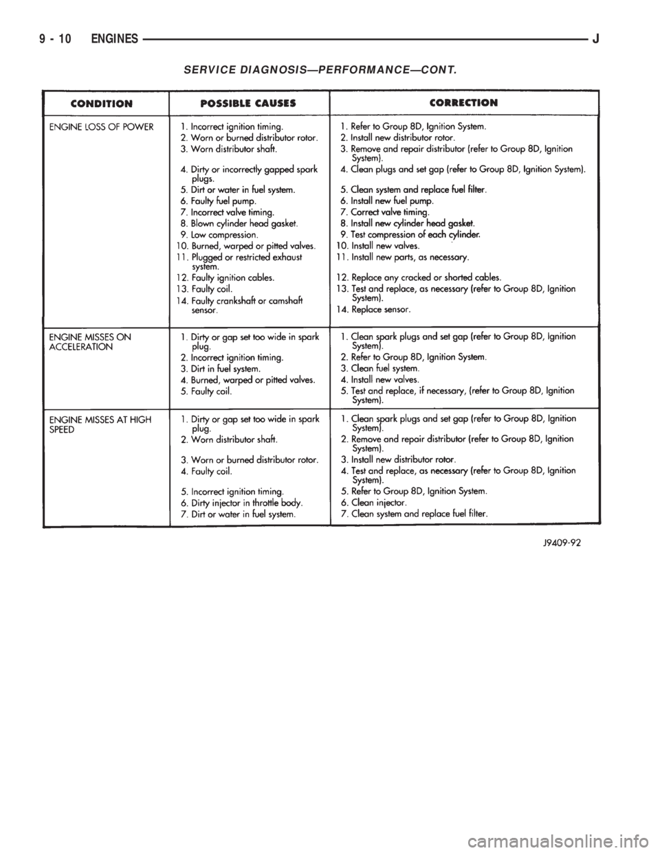
SERVICE DIAGNOSISÐPERFORMANCEÐCONT.
9 - 10 ENGINESJ
Page 1102 of 2198
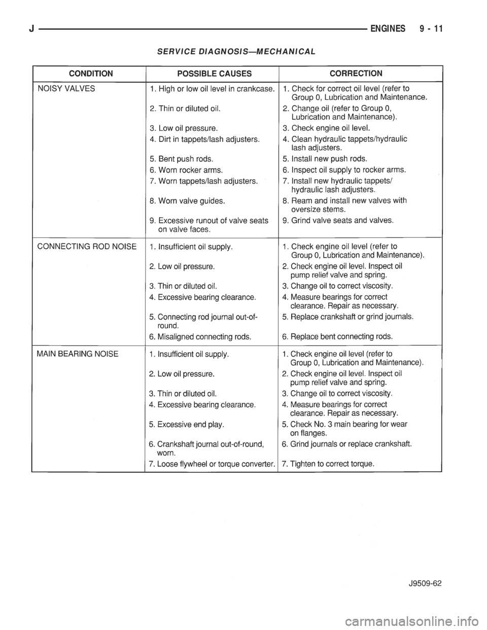
SERVICE DIAGNOSISÐMECHANICAL
JENGINES 9 - 11
Page 1103 of 2198
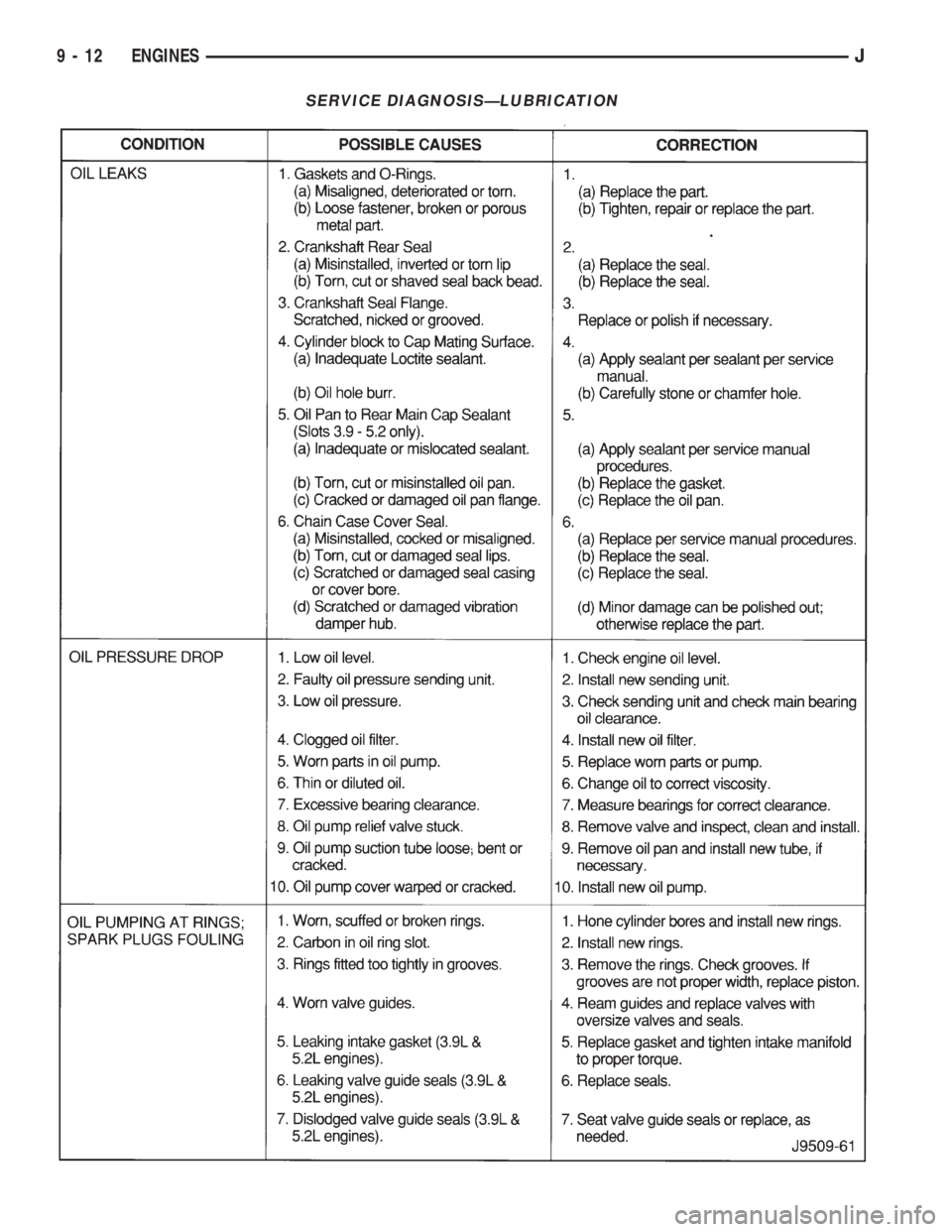
SERVICE DIAGNOSISÐLUBRICATION
9 - 12 ENGINESJ
Page 1104 of 2198
2.5L ENGINE SERVICE PROCEDURES
INDEX
page page
Camshaft............................... 32
Camshaft Pin Replacement.................. 34
Engine AssemblyÐXJ Vehicles............... 18
Engine AssemblyÐYJ Vehicles............... 20
Engine Cylinder Head...................... 25
Engine Cylinder Head Cover................. 22
Engine Damper........................... 17
Engine MountÐRear....................... 16
Engine MountsÐFront..................... 14
General Information....................... 13
Hydraulic Tappets......................... 24OilPan ................................. 36
Rocker Arms and Push Rods................ 23
Timing Case Cover........................ 31
Timing Case Cover Oil Seal Replacement....... 30
Timing Chain and Sprockets................. 31
Valve Component ReplaceÐCylinder Head Not
Removed.............................. 23
Valve Springs and Oil Seals................. 23
Valve Timing............................. 30
Valves and Valve Springs................... 27
Vibration Damper......................... 30
GENERAL INFORMATION
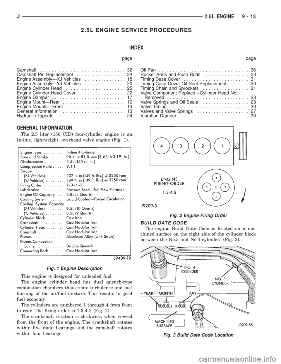
The 2.5 liter (150 CID) four-cylinder engine is an
In-line, lightweight, overhead valve engine (Fig. 1).
This engine is designed for unleaded fuel.
The engine cylinder head has dual quench-type
combustion chambers that create turbulence and fast
burning of the air/fuel mixture. This results in good
fuel economy.
The cylinders are numbered 1 through 4 from front
to rear. The firing order is 1-3-4-2 (Fig. 2).
The crankshaft rotation is clockwise, when viewed
from the front of the engine. The crankshaft rotates
within five main bearings and the camshaft rotates
within four bearings.
BUILD DATE CODE
The engine Build Date Code is located on a ma-
chined surface on the right side of the cylinder block
between the No.3 and No.4 cylinders (Fig. 3).
Fig. 1 Engine Description
Fig. 2 Engine Firing Order
Fig. 3 Build Date Code Location
J2.5L ENGINE 9 - 13
Page 1105 of 2198
The digits of the code identify:
(1) 1st DigitÐThe year (4 = 1994).
(2) 2nd & 3rd DigitsÐThe month (01 - 12).
(3) 4th & 5th DigitsÐThe engine type/fuel system/
compression ratio (HX = A 2.5 liter (150 CID) 9.1:1
compression ratio engine with a multi-point fuel in-
jection system).
(4) 6th & 7th DigitsÐThe day of engine build (01 -
31).
FOR EXAMPLE:Code * 401HX23 * identifies a
2.5 liter (150 CID) engine with a multi-point fuel in-
jection system, 9.1:1 compression ratio and built on
January 23, 1994.
OVERSIZE AND UNDERSIZE COMPONENT
CODES
Some engines may be built with oversize or under-
size components such as:
²Oversize cylinder bores.
²Oversize camshaft bearing bores.
²Undersize crankshaft main bearing journals.
²Undersize connecting rod journals.
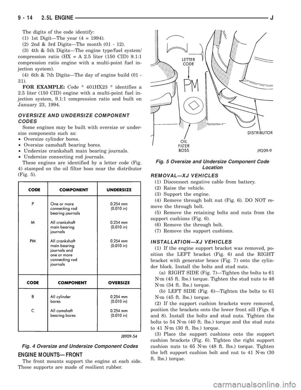
These engines are identified by a letter code (Fig.
4) stamped on the oil filter boss near the distributor
(Fig. 5).
ENGINE MOUNTSÐFRONT
The front mounts support the engine at each side.
These supports are made of resilient rubber.
REMOVALÐXJ VEHICLES
(1) Disconnect negative cable from battery.
(2) Raise the vehicle.
(3) Support the engine.
(4) Remove through bolt nut (Fig. 6). DO NOT re-
move the through bolt.
(5) Remove the retaining bolts and nuts from the
support cushions (Fig. 6).
(6) Remove the through bolt.
(7) Remove the support cushions.
INSTALLATIONÐXJ VEHICLES
(1) If the engine support bracket was removed, po-
sition the LEFT bracket (Fig. 6) and the RIGHT
bracket with generator brace (Fig. 7) onto the cylin-
der block. Install the bolts and stud nuts.
(a) RIGHT SIDE (Fig. 7)ÐTighten the bolts to 61
Nzm (45 ft. lbs.) torque. Tighten the stud nuts to 46
Nzm (34 ft. lbs.) torque.
(b) LEFT SIDE (Fig. 6)ÐTighten the bolts to 61
Nzm (45 ft. lbs.) torque.
(2) If the support cushion brackets were removed,
position the brackets onto the lower front sill (Figs. 6
and 8). Install the bolts and stud nuts. Tighten the
bolts to 54 Nzm (40 ft. lbs.) torque and the stud nuts
to 41 Nzm (30 ft. lbs.) torque.
(3) Place the support cushions onto the support
cushion brackets (Fig. 6). Tighten the right support
cushion nuts to 65 Nzm (48 ft. lbs.) torque. Tighten
the left support cushion bolt and nut to 41 Nzm (30
ft. lbs.) torque.
Fig. 4 Oversize and Undersize Component Codes
Fig. 5 Oversize and Undersize Component Code
Location
9 - 14 2.5L ENGINEJ
Page 1106 of 2198
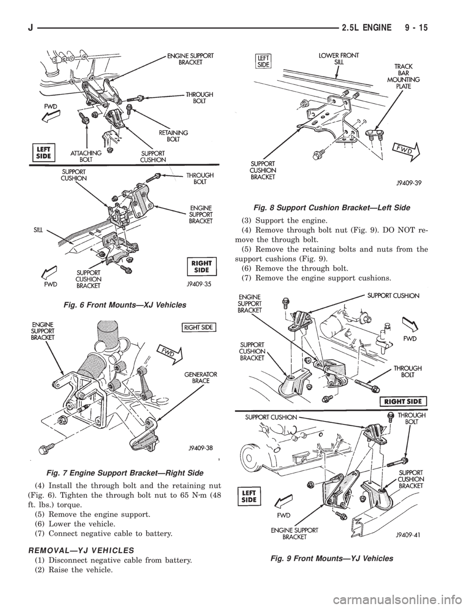
(4) Install the through bolt and the retaining nut
(Fig. 6). Tighten the through bolt nut to 65 Nzm (48
ft. lbs.) torque.
(5) Remove the engine support.
(6) Lower the vehicle.
(7) Connect negative cable to battery.
REMOVALÐYJ VEHICLES
(1) Disconnect negative cable from battery.
(2) Raise the vehicle.(3) Support the engine.
(4) Remove through bolt nut (Fig. 9). DO NOT re-
move the through bolt.
(5) Remove the retaining bolts and nuts from the
support cushions (Fig. 9).
(6) Remove the through bolt.
(7) Remove the engine support cushions.
Fig. 6 Front MountsÐXJ Vehicles
Fig. 7 Engine Support BracketÐRight Side
Fig. 8 Support Cushion BracketÐLeft Side
Fig. 9 Front MountsÐYJ Vehicles
J2.5L ENGINE 9 - 15
Page 1107 of 2198
INSTALLATIONÐYJ VEHICLES
(1) If the engine support bracket was removed, po-
sition the bracket onto the block and install the at-
taching bolts (Fig. 9). Tighten the bolts to 62 Nzm (46
ft. lbs.) torque.
(2) Place the support cushion on the support cush-
ion bracket (Fig. 9). Install the support cushion re-
taining bolts and nuts. Tighten the bolts and nuts to
52 Nzm (38 ft. lbs.) torque.
(3) Install the through bolt and the retaining nut
(Fig. 9). Tighten the through bolt nut to 69 Nzm (51
ft. lbs.) torque.
(4) Remove the engine support.
(5) Lower the vehicle.
(6) Connect negative cable to battery.
ENGINE MOUNTÐREAR
A resilient rubber cushion supports the transmis-
sion at the rear between the transmission extension
housing and the rear support crossmember or skid
plate.
REMOVALÐXJ VEHICLES
(1) Disconnect negative cable from battery.
(2) Raise the vehicle and support the transmission.
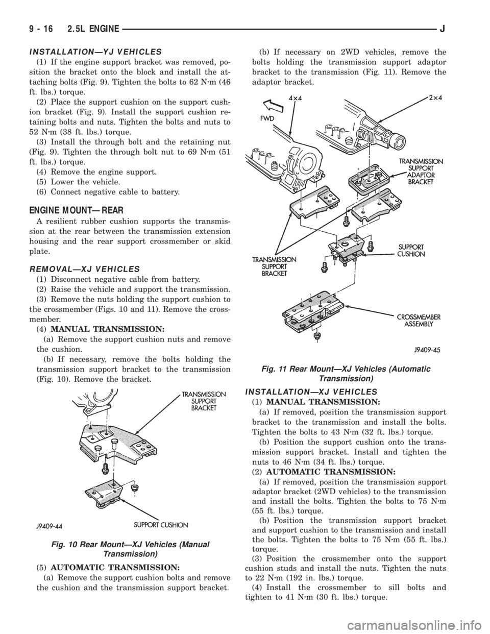
(3) Remove the nuts holding the support cushion to
the crossmember (Figs. 10 and 11). Remove the cross-
member.
(4)MANUAL TRANSMISSION:
(a) Remove the support cushion nuts and remove
the cushion.
(b) If necessary, remove the bolts holding the
transmission support bracket to the transmission
(Fig. 10). Remove the bracket.
(5)AUTOMATIC TRANSMISSION:
(a) Remove the support cushion bolts and remove
the cushion and the transmission support bracket.(b) If necessary on 2WD vehicles, remove the
bolts holding the transmission support adaptor
bracket to the transmission (Fig. 11). Remove the
adaptor bracket.
INSTALLATIONÐXJ VEHICLES
(1)MANUAL TRANSMISSION:
(a) If removed, position the transmission support
bracket to the transmission and install the bolts.
Tighten the bolts to 43 Nzm (32 ft. lbs.) torque.
(b) Position the support cushion onto the trans-
mission support bracket. Install and tighten the
nuts to 46 Nzm (34 ft. lbs.) torque.
(2)AUTOMATIC TRANSMISSION:
(a) If removed, position the transmission support
adaptor bracket (2WD vehicles) to the transmission
and install the bolts. Tighten the bolts to 75 Nzm
(55 ft. lbs.) torque.
(b) Position the transmission support bracket
and support cushion to the transmission and install
the bolts. Tighten the bolts to 75 Nzm (55 ft. lbs.)
torque.
(3) Position the crossmember onto the support
cushion studs and install the nuts. Tighten the nuts
to 22 Nzm (192 in. lbs.) torque.
(4) Install the crossmember to sill bolts and
tighten to 41 Nzm (30 ft. lbs.) torque.
Fig. 10 Rear MountÐXJ Vehicles (Manual
Transmission)
Fig. 11 Rear MountÐXJ Vehicles (Automatic
Transmission)
9 - 16 2.5L ENGINEJ
Page 1108 of 2198
(5) Remove the transmission support.
(6) Lower the vehicle.
(7) Connect negative cable to battery.
REMOVALÐYJ VEHICLES
(1) Disconnect negative cable from battery.
(2) Raise the vehicle and support the transmission.
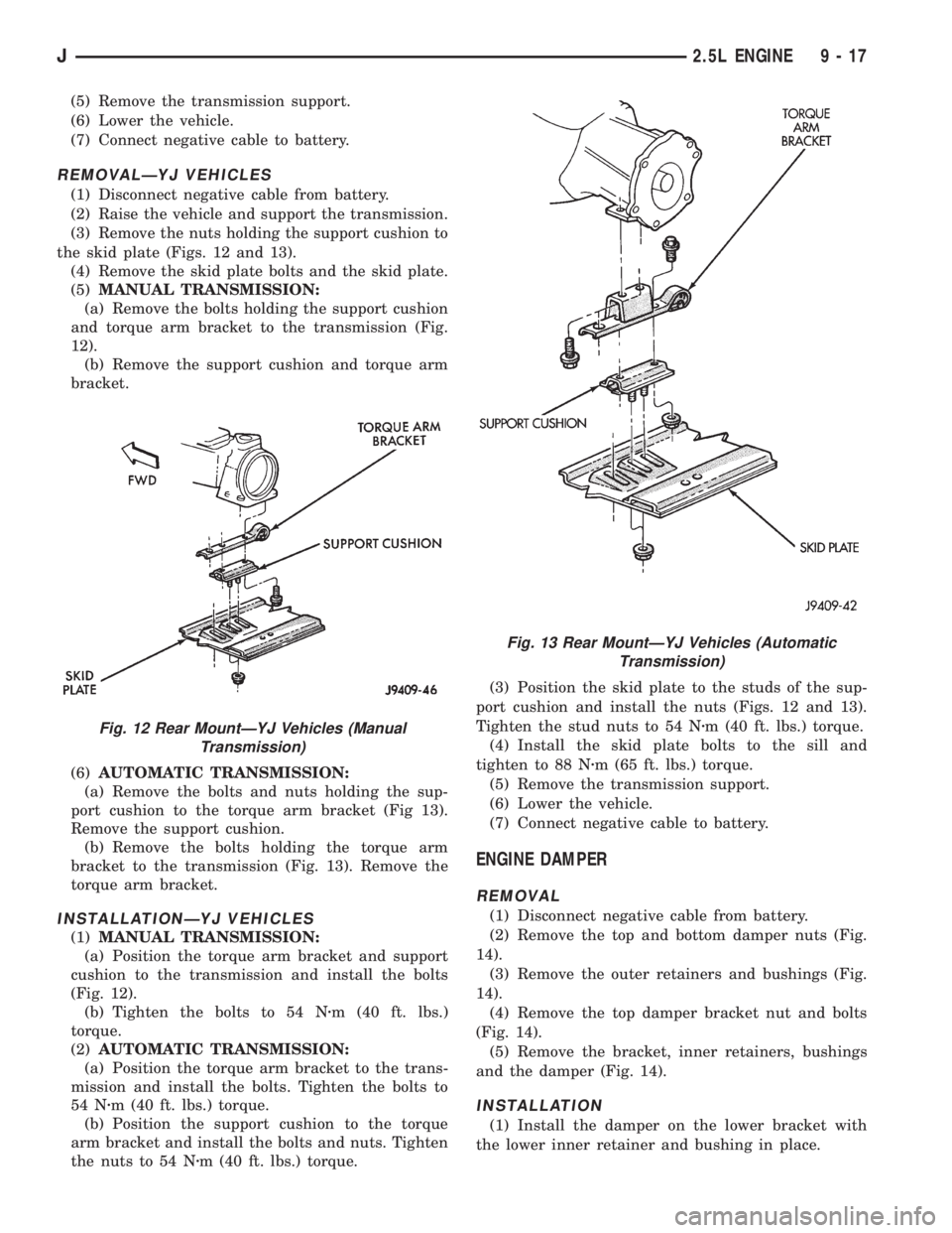
(3) Remove the nuts holding the support cushion to
the skid plate (Figs. 12 and 13).
(4) Remove the skid plate bolts and the skid plate.
(5)MANUAL TRANSMISSION:
(a) Remove the bolts holding the support cushion
and torque arm bracket to the transmission (Fig.
12).
(b) Remove the support cushion and torque arm
bracket.
(6)AUTOMATIC TRANSMISSION:
(a) Remove the bolts and nuts holding the sup-
port cushion to the torque arm bracket (Fig 13).
Remove the support cushion.
(b) Remove the bolts holding the torque arm
bracket to the transmission (Fig. 13). Remove the
torque arm bracket.
INSTALLATIONÐYJ VEHICLES
(1)MANUAL TRANSMISSION:
(a) Position the torque arm bracket and support
cushion to the transmission and install the bolts
(Fig. 12).
(b) Tighten the bolts to 54 Nzm (40 ft. lbs.)
torque.
(2)AUTOMATIC TRANSMISSION:
(a) Position the torque arm bracket to the trans-
mission and install the bolts. Tighten the bolts to
54 Nzm (40 ft. lbs.) torque.
(b) Position the support cushion to the torque
arm bracket and install the bolts and nuts. Tighten
the nuts to 54 Nzm (40 ft. lbs.) torque.(3) Position the skid plate to the studs of the sup-
port cushion and install the nuts (Figs. 12 and 13).
Tighten the stud nuts to 54 Nzm (40 ft. lbs.) torque.
(4) Install the skid plate bolts to the sill and
tighten to 88 Nzm (65 ft. lbs.) torque.
(5) Remove the transmission support.
(6) Lower the vehicle.
(7) Connect negative cable to battery.
ENGINE DAMPER
REMOVAL
(1) Disconnect negative cable from battery.
(2) Remove the top and bottom damper nuts (Fig.
14).
(3) Remove the outer retainers and bushings (Fig.
14).
(4) Remove the top damper bracket nut and bolts
(Fig. 14).
(5) Remove the bracket, inner retainers, bushings
and the damper (Fig. 14).
INSTALLATION
(1) Install the damper on the lower bracket with
the lower inner retainer and bushing in place.
Fig. 12 Rear MountÐYJ Vehicles (Manual
Transmission)
Fig. 13 Rear MountÐYJ Vehicles (Automatic
Transmission)
J2.5L ENGINE 9 - 17
Page 1109 of 2198
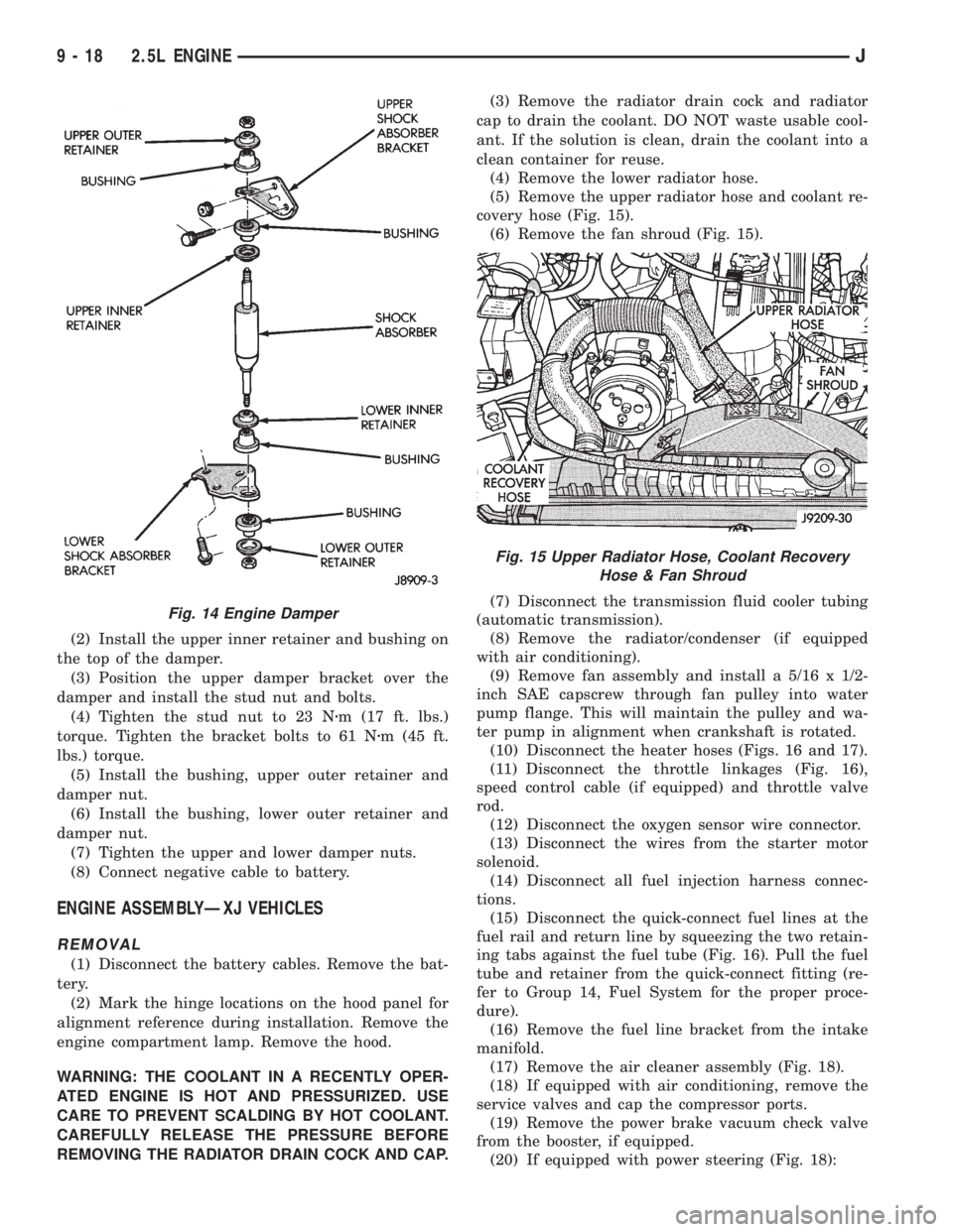
(2) Install the upper inner retainer and bushing on
the top of the damper.
(3) Position the upper damper bracket over the
damper and install the stud nut and bolts.
(4) Tighten the stud nut to 23 Nzm (17 ft. lbs.)
torque. Tighten the bracket bolts to 61 Nzm (45 ft.
lbs.) torque.
(5) Install the bushing, upper outer retainer and
damper nut.
(6) Install the bushing, lower outer retainer and
damper nut.
(7) Tighten the upper and lower damper nuts.
(8) Connect negative cable to battery.
ENGINE ASSEMBLYÐXJ VEHICLES
REMOVAL
(1) Disconnect the battery cables. Remove the bat-
tery.
(2) Mark the hinge locations on the hood panel for
alignment reference during installation. Remove the
engine compartment lamp. Remove the hood.
WARNING: THE COOLANT IN A RECENTLY OPER-
ATED ENGINE IS HOT AND PRESSURIZED. USE
CARE TO PREVENT SCALDING BY HOT COOLANT.
CAREFULLY RELEASE THE PRESSURE BEFORE
REMOVING THE RADIATOR DRAIN COCK AND CAP.(3) Remove the radiator drain cock and radiator
cap to drain the coolant. DO NOT waste usable cool-
ant. If the solution is clean, drain the coolant into a
clean container for reuse.
(4) Remove the lower radiator hose.
(5) Remove the upper radiator hose and coolant re-
covery hose (Fig. 15).
(6) Remove the fan shroud (Fig. 15).
(7) Disconnect the transmission fluid cooler tubing
(automatic transmission).
(8) Remove the radiator/condenser (if equipped
with air conditioning).
(9) Remove fan assembly and install a 5/16 x 1/2-
inch SAE capscrew through fan pulley into water
pump flange. This will maintain the pulley and wa-
ter pump in alignment when crankshaft is rotated.
(10) Disconnect the heater hoses (Figs. 16 and 17).
(11) Disconnect the throttle linkages (Fig. 16),
speed control cable (if equipped) and throttle valve
rod.
(12) Disconnect the oxygen sensor wire connector.
(13) Disconnect the wires from the starter motor
solenoid.
(14) Disconnect all fuel injection harness connec-
tions.
(15) Disconnect the quick-connect fuel lines at the
fuel rail and return line by squeezing the two retain-
ing tabs against the fuel tube (Fig. 16). Pull the fuel
tube and retainer from the quick-connect fitting (re-
fer to Group 14, Fuel System for the proper proce-
dure).
(16) Remove the fuel line bracket from the intake
manifold.
(17) Remove the air cleaner assembly (Fig. 18).
(18) If equipped with air conditioning, remove the
service valves and cap the compressor ports.
(19) Remove the power brake vacuum check valve
from the booster, if equipped.
(20) If equipped with power steering (Fig. 18):
Fig. 14 Engine Damper
Fig. 15 Upper Radiator Hose, Coolant Recovery
Hose & Fan Shroud
9 - 18 2.5L ENGINEJ
Page 1110 of 2198
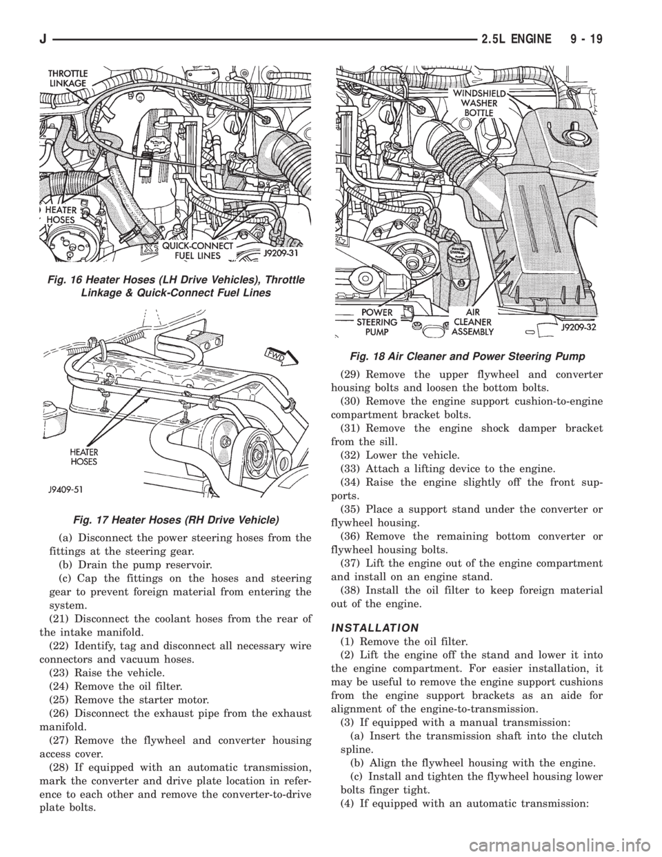
(a) Disconnect the power steering hoses from the
fittings at the steering gear.
(b) Drain the pump reservoir.
(c) Cap the fittings on the hoses and steering
gear to prevent foreign material from entering the
system.
(21) Disconnect the coolant hoses from the rear of
the intake manifold.
(22) Identify, tag and disconnect all necessary wire
connectors and vacuum hoses.
(23) Raise the vehicle.
(24) Remove the oil filter.
(25) Remove the starter motor.
(26) Disconnect the exhaust pipe from the exhaust
manifold.
(27) Remove the flywheel and converter housing
access cover.
(28) If equipped with an automatic transmission,
mark the converter and drive plate location in refer-
ence to each other and remove the converter-to-drive
plate bolts.(29) Remove the upper flywheel and converter
housing bolts and loosen the bottom bolts.
(30) Remove the engine support cushion-to-engine
compartment bracket bolts.
(31) Remove the engine shock damper bracket
from the sill.
(32) Lower the vehicle.
(33) Attach a lifting device to the engine.
(34) Raise the engine slightly off the front sup-
ports.
(35) Place a support stand under the converter or
flywheel housing.
(36) Remove the remaining bottom converter or
flywheel housing bolts.
(37) Lift the engine out of the engine compartment
and install on an engine stand.
(38) Install the oil filter to keep foreign material
out of the engine.
INSTALLATION
(1) Remove the oil filter.
(2) Lift the engine off the stand and lower it into
the engine compartment. For easier installation, it
may be useful to remove the engine support cushions
from the engine support brackets as an aide for
alignment of the engine-to-transmission.
(3) If equipped with a manual transmission:
(a) Insert the transmission shaft into the clutch
spline.
(b) Align the flywheel housing with the engine.
(c) Install and tighten the flywheel housing lower
bolts finger tight.
(4) If equipped with an automatic transmission:
Fig. 16 Heater Hoses (LH Drive Vehicles), Throttle
Linkage & Quick-Connect Fuel Lines
Fig. 17 Heater Hoses (RH Drive Vehicle)
Fig. 18 Air Cleaner and Power Steering Pump
J2.5L ENGINE 9 - 19