JEEP CHEROKEE 1995 Service Repair Manual
Manufacturer: JEEP, Model Year: 1995, Model line: CHEROKEE, Model: JEEP CHEROKEE 1995Pages: 2198, PDF Size: 82.83 MB
Page 2111 of 2198
Page 2112 of 2198
Page 2113 of 2198

Page 2114 of 2198
WIPERS
INDEX
page page
Diagram Index............................ 2
Rear Wiper System......................... 1WipersÐIntermittent........................ 1
WipersÐStandard.......................... 1
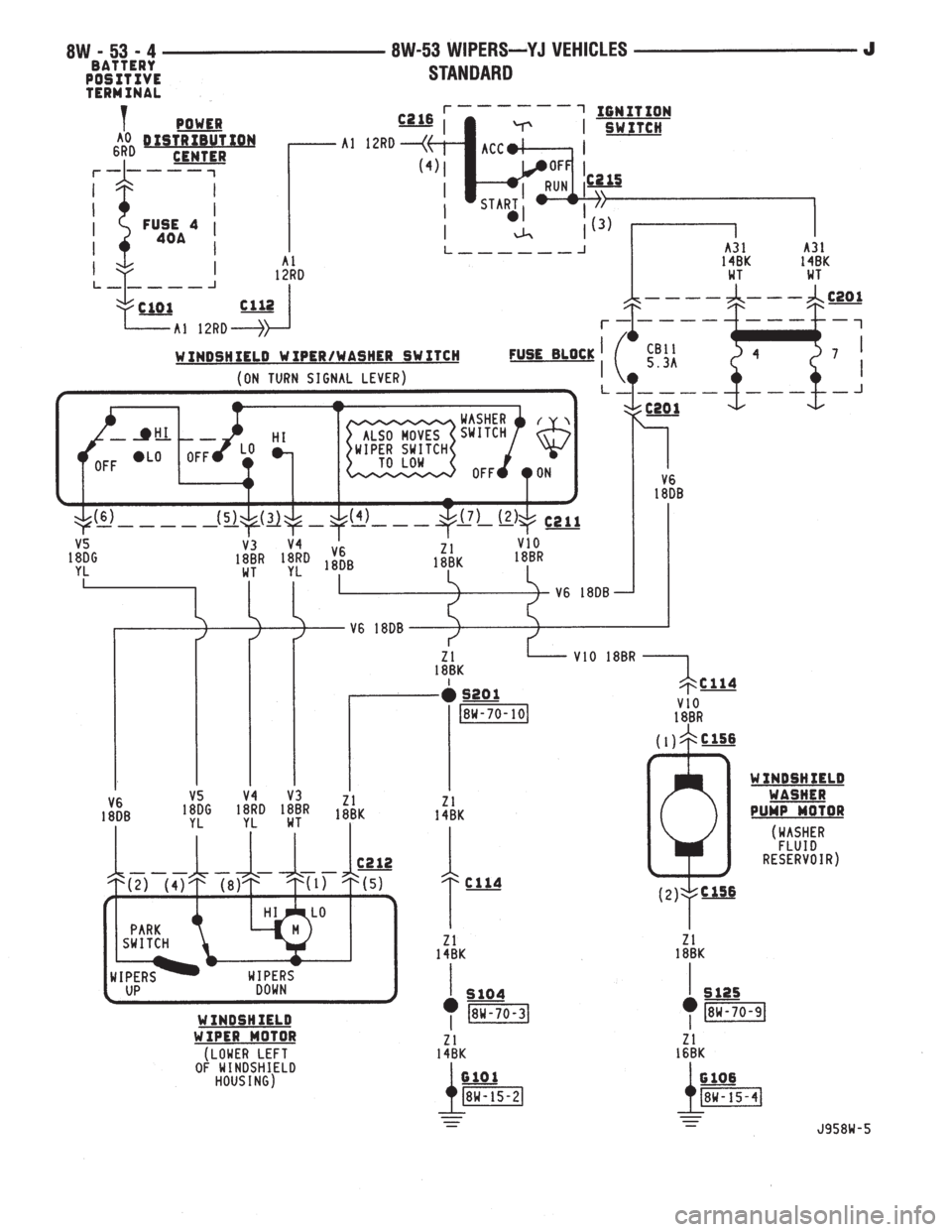
WIPERSÐSTANDARD
A circuit breaker in the fuse block powers the stan-
dard wiper system. The standard wiper system oper-
ates at either LOW or HIGH speeds.
In the ACCESSORY or RUN position, the ignition
switch connects circuit A1 from fuse 4 in the Power
Distribution Center (PDC) with circuit A31. Circuit
A31 supplies voltage to circuit V6 through the circuit
breaker in cavity 11 of the fuse block.
Circuit V6 is double crimped at the circuit breaker
and supplies power to the wiper switch and the park
switch in the wiper motor. Circuit Z1 provides
ground for the wiper motor and switch.
When the operator moves the wiper switch to the
LOW position, battery voltage passes through the
switch to circuit V3. Circuit V3 feeds the wiper motor
low speed brushes. If the operator selects wiper
HIGH speed operation, the wiper switch passes cur-
rent to circuit V4. Circuit V4 feeds the wiper motor
high speed brushes.
As the windshield wiper motor turns, the park
switch, internal to the motor, moves from its DOWN
position to the UP position. When the wiper switch is
turned OFF, the V5 circuit prevents the wipers from
stopping in any position but park.
The windshield washer uses a pump motor located
inside the windshield washer fluid reservoir. When
the washer switch is pressed, power is supplied
through the wiper switch to the pump motor on cir-
cuit V10. Circuit Z1 provide ground for the pump mo-
tor.
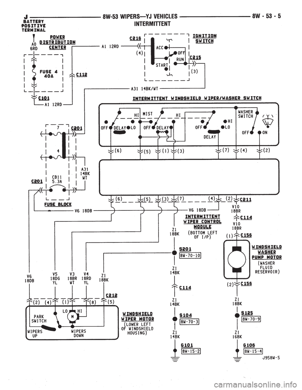
WIPERSÐINTERMITTENT
A circuit breaker in the fuse block powers the in-
termittent wiper system. The wiper system operates
at either LOW, HIGH, or DELAY speeds.
In the ACCESSORY or RUN position, the ignition
switch connects circuit A1 from fuse 4 in the Power
Distribution Center (PDC) with circuit A31. Circuit
A31 supplies voltage to circuit V6 through the circuit
breaker in cavity 11 of the fuse block.
Circuit V6 is double crimped at the circuit breaker
and supplies power to the wiper switch and the park
switch in the wiper motor. Circuit Z1 provides
ground for the wiper motor and switch.When the operator moves the wiper switch to the
LOW position, battery voltage passes through the
switch to circuit V3. Circuit V3 feeds the wiper motor
low speed brushes. If the operator selects wiper
HIGH speed operation, the wiper switch passes cur-
rent to circuit V4. Circuit V4 feeds the wiper motor
high speed brushes.
The DELAY portion of the wiper switch contains a
variable resistor. The variable resistor connects to
the intermittent wiper module through the wiper
switch harness. The amount of delay selected by the
operator determines the voltage drop through the re-
sistor and the voltage level received by the intermit-
tent wiper module.
After the intermittent wiper control module deter-
mines the amount of delay selected, it cycles the wip-
ers by periodically energizing circuit V3. Circuit V3
powers the wiper motor low speed brushes.
As the windshield wiper motor turns, the park
switch, internal to the motor, moves from its DOWN
position to the UP position. When the wiper switch is
turned OFF, the V5 circuit prevents the wipers from
stopping in any position but park.
The windshield washer uses a pump motor located
inside the windshield washer fluid reservoir. When
the washer switch is pressed, power is supplied
through the wiper switch to the pump motor on cir-
cuit V10. Circuit Z1 provides ground for the pump
motor.
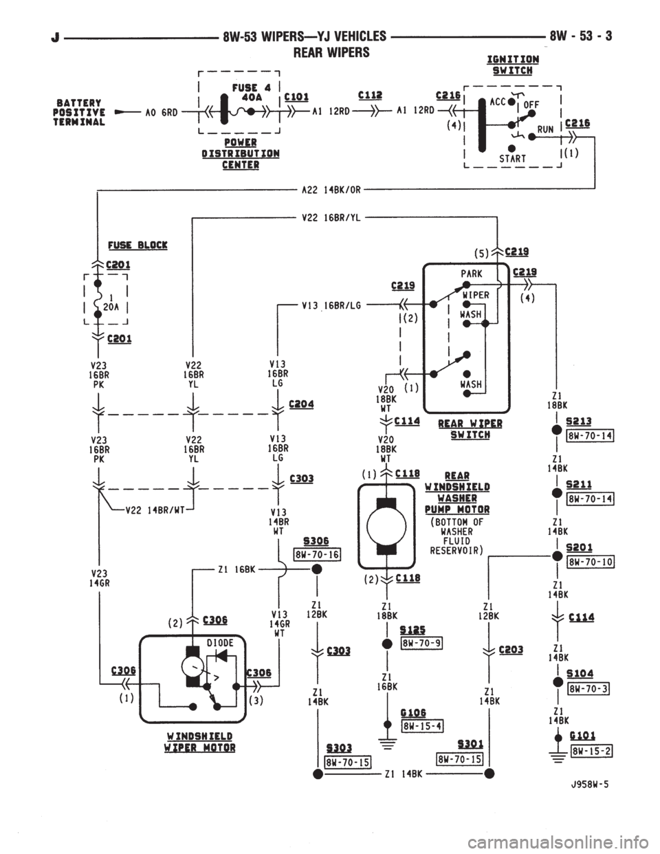
REAR WIPER SYSTEM
In the RUN position, the ignition switch connects
circuit A1 from fuse 4 in the Power Distribution Cen-
ter (PDC) with circuit A22. Circuit A22 connects to a
fuse block in the bus bar that powers circuit V23
through the fuse in cavity 1.
Circuit V23 supplies power to the park switch in
the rear wiper motor. Also, circuit V22 is crimped to
circuit V23 at the rear wiper motor connector. Circuit
V22 supplies current to the rear wiper switch.
In the WIPE or WASH positions, the rear wiper
switch supplies voltage to the wiper motor on circuit
V13. Circuit Z1 provides ground for the wiper motor.
J8W-53 WIPERSÐYJ VEHICLES 8W - 53 - 1
Page 2115 of 2198
The rear windshield washer uses a pump motor lo-
cated inside the windshield washer fluid reservoir.
When the rear wiper switch is pressed, power is sup-
plied through the wiper switch to the pump motor on
circuit V20. Circuit Z1 provides ground for the pump
motor.DIAGRAM INDEX
Component Page
Circuit Breaker (Fuse Block Cavity 11).........8W-53-4, 5
Fuse 4 (PDC).......................8W-53-3, 4, 5,
Fuse 4 (Fuse Block).....................8W-53-4, 5
Fuse 7 (Fuse Block).....................8W-53-4, 5
Ignition Switch......................8W-53-3, 4, 5
Intermittent Wiper Control Module.............8W-53-5
Intermittent Wiper Switch...................8W-53-5
Rear Windshield Washer Pump Motor...........8W-53-3
Rear Wiper Motor........................8W-53-3
Standard Wiper Switch.....................8W-53-4
Windshield Washer Pump Motor.............8W-53-4, 5
Wiper Motor..........................8W-53-4, 5
8W - 53 - 2 8W-53 WIPERSÐYJ VEHICLESJ
Page 2116 of 2198
Page 2117 of 2198
Page 2118 of 2198
Page 2119 of 2198

Page 2120 of 2198
SPLICE INFORMATION
GENERAL INFORMATION
This section identifies all splices in the wiring dia-
grams. It also shows the splices in their entirety. All
circuits that are part of the splices are shown, and
the systems they affect are referenced. For viewing
the location of each splice in the vehicle, refer to Sec-
tion 8W-95.
SPLICE INDEX
Component Page
S101................................8W-70-2
S102................................8W-70-2
S103................................8W-70-2
S104................................8W-70-3
S105................................8W-70-3
S106................................8W-70-3
S107................................8W-70-4
S108................................8W-70-4
S109................................8W-70-4
S110................................8W-70-5
S111................................8W-70-5
S112................................8W-70-5
S113................................8W-70-5
S114................................8W-70-6
S115................................8W-70-6
S116................................8W-70-6
S117................................8W-70-7
S118................................8W-70-7
S119................................8W-70-7
S120................................8W-70-8
S121................................8W-70-8
S122................................8W-70-8
S123................................8W-70-8
S124................................8W-70-8
S125................................8W-70-9Component Page
S126................................8W-70-9
S127................................8W-70-9
S128................................8W-70-9
S129................................8W-70-10
S201................................8W-70-10
S202................................8W-70-10
S203................................8W-70-11
S204................................8W-70-11
S207................................8W-70-12
S208................................8W-70-12
S209................................8W-70-13
S210................................8W-70-13
S211................................8W-70-14
S212................................8W-70-14
S213................................8W-70-14
S301................................8W-70-15
S302................................8W-70-15
S303................................8W-70-15
S304................................8W-70-15
S305................................8W-70-16
S306................................8W-70-16
S307................................8W-70-16
S308................................8W-70-16
J8W-70 SPLICE INFORMATIONÐYJ VEHICLES 8W - 70 - 1