thermostat JEEP CHEROKEE 1995 Service Owner's Manual
[x] Cancel search | Manufacturer: JEEP, Model Year: 1995, Model line: CHEROKEE, Model: JEEP CHEROKEE 1995Pages: 2198, PDF Size: 82.83 MB
Page 1158 of 2198
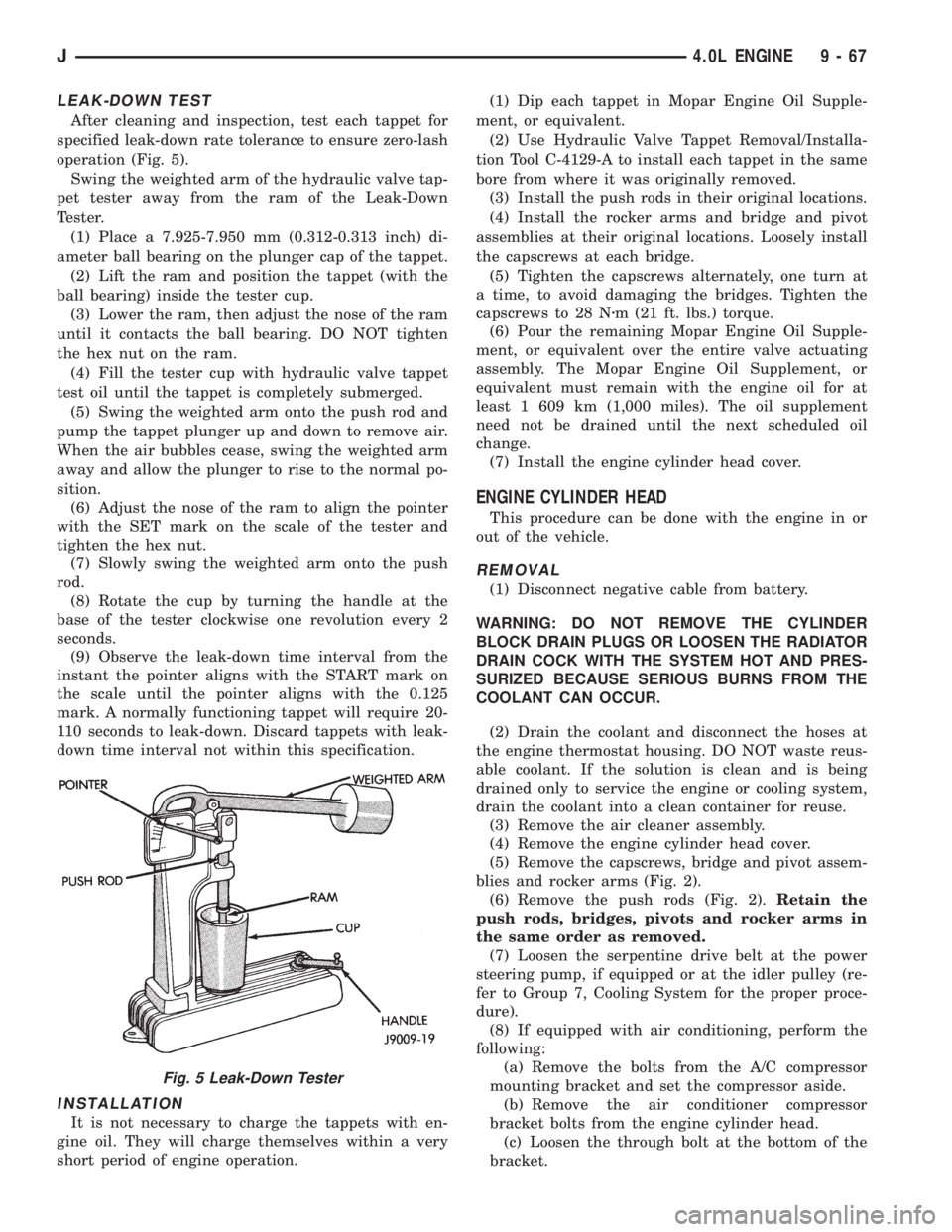
LEAK-DOWN TEST
After cleaning and inspection, test each tappet for
specified leak-down rate tolerance to ensure zero-lash
operation (Fig. 5).
Swing the weighted arm of the hydraulic valve tap-
pet tester away from the ram of the Leak-Down
Tester.
(1) Place a 7.925-7.950 mm (0.312-0.313 inch) di-
ameter ball bearing on the plunger cap of the tappet.
(2) Lift the ram and position the tappet (with the
ball bearing) inside the tester cup.
(3) Lower the ram, then adjust the nose of the ram
until it contacts the ball bearing. DO NOT tighten
the hex nut on the ram.
(4) Fill the tester cup with hydraulic valve tappet
test oil until the tappet is completely submerged.
(5) Swing the weighted arm onto the push rod and
pump the tappet plunger up and down to remove air.
When the air bubbles cease, swing the weighted arm
away and allow the plunger to rise to the normal po-
sition.
(6) Adjust the nose of the ram to align the pointer
with the SET mark on the scale of the tester and
tighten the hex nut.
(7) Slowly swing the weighted arm onto the push
rod.
(8) Rotate the cup by turning the handle at the
base of the tester clockwise one revolution every 2
seconds.
(9) Observe the leak-down time interval from the
instant the pointer aligns with the START mark on
the scale until the pointer aligns with the 0.125
mark. A normally functioning tappet will require 20-
110 seconds to leak-down. Discard tappets with leak-
down time interval not within this specification.
INSTALLATION
It is not necessary to charge the tappets with en-
gine oil. They will charge themselves within a very
short period of engine operation.(1) Dip each tappet in Mopar Engine Oil Supple-
ment, or equivalent.
(2) Use Hydraulic Valve Tappet Removal/Installa-
tion Tool C-4129-A to install each tappet in the same
bore from where it was originally removed.
(3) Install the push rods in their original locations.
(4) Install the rocker arms and bridge and pivot
assemblies at their original locations. Loosely install
the capscrews at each bridge.
(5) Tighten the capscrews alternately, one turn at
a time, to avoid damaging the bridges. Tighten the
capscrews to 28 Nzm (21 ft. lbs.) torque.
(6) Pour the remaining Mopar Engine Oil Supple-
ment, or equivalent over the entire valve actuating
assembly. The Mopar Engine Oil Supplement, or
equivalent must remain with the engine oil for at
least 1 609 km (1,000 miles). The oil supplement
need not be drained until the next scheduled oil
change.
(7) Install the engine cylinder head cover.
ENGINE CYLINDER HEAD
This procedure can be done with the engine in or
out of the vehicle.
REMOVAL
(1) Disconnect negative cable from battery.
WARNING: DO NOT REMOVE THE CYLINDER
BLOCK DRAIN PLUGS OR LOOSEN THE RADIATOR
DRAIN COCK WITH THE SYSTEM HOT AND PRES-
SURIZED BECAUSE SERIOUS BURNS FROM THE
COOLANT CAN OCCUR.
(2) Drain the coolant and disconnect the hoses at
the engine thermostat housing. DO NOT waste reus-
able coolant. If the solution is clean and is being
drained only to service the engine or cooling system,
drain the coolant into a clean container for reuse.
(3) Remove the air cleaner assembly.
(4) Remove the engine cylinder head cover.
(5) Remove the capscrews, bridge and pivot assem-
blies and rocker arms (Fig. 2).
(6) Remove the push rods (Fig. 2).Retain the
push rods, bridges, pivots and rocker arms in
the same order as removed.
(7) Loosen the serpentine drive belt at the power
steering pump, if equipped or at the idler pulley (re-
fer to Group 7, Cooling System for the proper proce-
dure).
(8) If equipped with air conditioning, perform the
following:
(a) Remove the bolts from the A/C compressor
mounting bracket and set the compressor aside.
(b) Remove the air conditioner compressor
bracket bolts from the engine cylinder head.
(c) Loosen the through bolt at the bottom of the
bracket.
Fig. 5 Leak-Down Tester
J4.0L ENGINE 9 - 67
Page 1160 of 2198
counter bolts which were painted in an earlier ser-
vice operation, replace them.
(6) Install the ignition coil and bracket assembly.
(7) Connect the temperature sending unit wire
connector.
(8) Install the spark plugs and tighten to 37 Nzm
(27 ft. lbs.) torque. Connect the ignition wires.
(9) Install the intake and engine exhaust mani-
folds (refer to Group 11, Exhaust System and Intake
Manifold for the proper procedures).
(10) Install the fuel lines and the vacuum advance
hose.
(11) If equipped, attach the power steering pump
and bracket.
(12) Install the push rods, rocker arms, pivots and
bridges in the order they were removed (refer to
Rocker Arms and Push Rods in this section).
(13) Install the engine cylinder head cover.
(14) Attach the air conditioner compressor mount-
ing bracket to the engine cylinder head and block.
Tighten the bolts to 40 Nzm (30 ft. lbs.) torque.
(15) Attach the air conditioning compressor to the
bracket. Tighten the bolts to 27 Nzm (20 ft. lbs.)
torque.
CAUTION: The serpentine drive belt must be routed
correctly. Incorrect routing can cause the water
pump to turn in the opposite direction causing the
engine to overheat.
(16) Install the serpentine drive belt and correctly
tension the belt (refer to Group 7, Cooling System for
the proper procedure).
(17) Install the air cleaner and ducting.
(18) Install the engine cylinder head cover.
(19) Connect the hoses to the engine thermostat
housing and fill the cooling system to the specified
level (refer to Group 7, Cooling Systems for the
proper procedure).
(20) The automatic transmission throttle linkage
and cable must be adjusted after completing the en-
gine cylinder head installation (refer to Group 21,
Transmissions for the proper procedures).(21) Install the temperature sending unit and con-
nect the wire connector.
(22) Connect the fuel line.
(23) Connect negative cable to battery.
(24) Connect the upper radiator hose and heater
hose at the engine thermostat housing.
(25) Fill the cooling system. Check for leaks.
WARNING: USE EXTREME CAUTION WHEN THE
ENGINE IS OPERATING. DO NOT STAND IN DIRECT
LINE WITH THE FAN. DO NOT PUT HANDS NEAR
THE PULLEYS, BELTS OR FAN. DO NOT WEAR
LOOSE CLOTHING.
(26) Operate the engine with the radiator cap off.
Inspect for leaks and continue operating the engine
until the engine thermostat opens. Add coolant, if re-
quired.
VALVES AND VALVE SPRINGS
This procedure is done with the engine cylinder
head removed from the block.
REMOVAL
(1) Remove the engine cylinder head from the cyl-
inder block.
(2) Use Valve Spring Compressor Tool
MD-998772A and compress each valve spring.
(3) Remove the valve locks, retainers, springs and
valve stem oil seals. Discard the oil seals.
(4) Use an Arkansas smooth stone or a jewelers
file to remove any burrs on the top of the valve stem,
especially around the groove for the locks.
(5) Remove the valves, and place them in a rack in
the same order as removed.
VALVE CLEANING
Clean all carbon deposits from the combustion
chambers, valve ports, valve stems, valve stem
guides and head.
Clean all grime and gasket material from the en-
gine cylinder head machined gasket surface.
INSPECTION
Inspect for cracks in the combustion chambers and
valve ports.
Inspect for cracks on the exhaust seat.
Inspect for cracks in the gasket surface at each
coolant passage.
Inspect valves for burned, cracked or warped
heads.
Inspect for scuffed or bent valve stems.
Replace valves displaying any damage.
VALVE REFACING
(1) Use a valve refacing machine to reface the in-
take and exhaust valves to the specified angle.
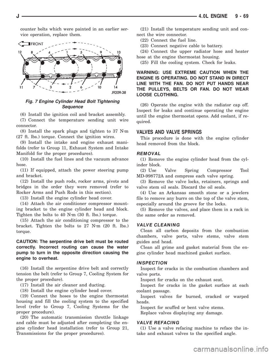
Fig. 7 Engine Cylinder Head Bolt Tightening
Sequence
J4.0L ENGINE 9 - 69
Page 1195 of 2198
CAUTION: When disconnecting the cruise control
connector at the throttle body, DO NOT pry the con-
nector off with pliers or screwdriver. Use finger
pressure only. Prying the connector off could break
it.
(9) Disconnect the electrical connectors. Pull the
harnesses away from the manifold.
²The throttle position sensor.
²The idle speed control motor.
²The coolant temperature sensor at the thermostat.
²The manifold air temperature sensor at the intake
manifold.
²The fuel injectors.
²The oxygen sensor.
(10) Disconnect the crankcase ventilation (CCV)
vacuum hose and manifold absolute pressure (MAP)
sensor vacuum hose connector at the intake mani-
fold.
(11) Disconnect vacuum hose from vacuum port on
the intake manifold.
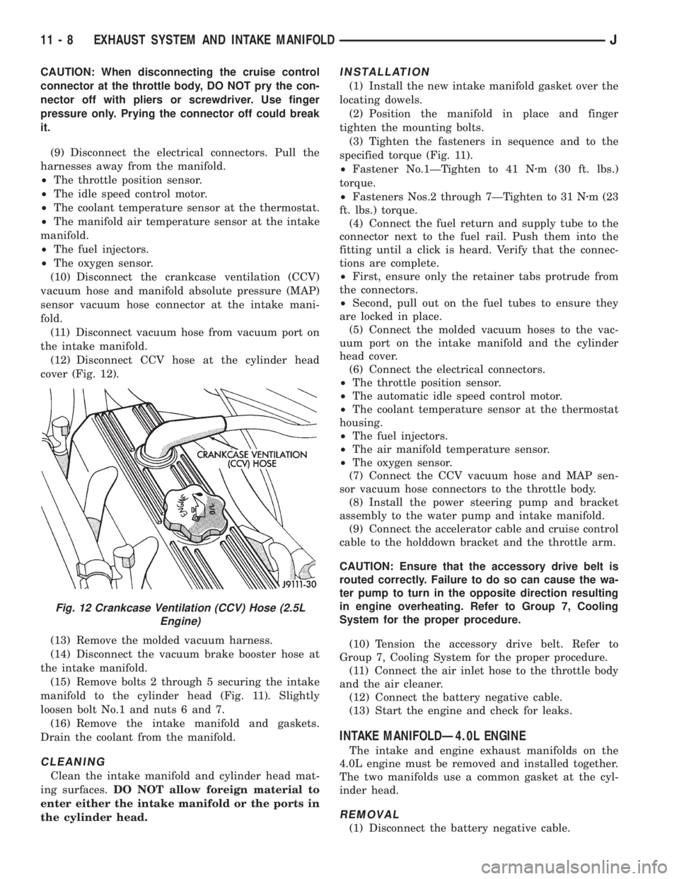
(12) Disconnect CCV hose at the cylinder head
cover (Fig. 12).
(13) Remove the molded vacuum harness.
(14) Disconnect the vacuum brake booster hose at
the intake manifold.
(15) Remove bolts 2 through 5 securing the intake
manifold to the cylinder head (Fig. 11). Slightly
loosen bolt No.1 and nuts 6 and 7.
(16) Remove the intake manifold and gaskets.
Drain the coolant from the manifold.
CLEANING
Clean the intake manifold and cylinder head mat-
ing surfaces.DO NOT allow foreign material to
enter either the intake manifold or the ports in
the cylinder head.
INSTALLATION
(1) Install the new intake manifold gasket over the
locating dowels.
(2) Position the manifold in place and finger
tighten the mounting bolts.
(3) Tighten the fasteners in sequence and to the
specified torque (Fig. 11).
²Fastener No.1ÐTighten to 41 Nzm (30 ft. lbs.)
torque.
²Fasteners Nos.2 through 7ÐTighten to 31 Nzm (23
ft. lbs.) torque.
(4) Connect the fuel return and supply tube to the
connector next to the fuel rail. Push them into the
fitting until a click is heard. Verify that the connec-
tions are complete.
²First, ensure only the retainer tabs protrude from
the connectors.
²Second, pull out on the fuel tubes to ensure they
are locked in place.
(5) Connect the molded vacuum hoses to the vac-
uum port on the intake manifold and the cylinder
head cover.
(6) Connect the electrical connectors.
²The throttle position sensor.
²The automatic idle speed control motor.
²The coolant temperature sensor at the thermostat
housing.
²The fuel injectors.
²The air manifold temperature sensor.
²The oxygen sensor.
(7) Connect the CCV vacuum hose and MAP sen-
sor vacuum hose connectors to the throttle body.
(8) Install the power steering pump and bracket
assembly to the water pump and intake manifold.
(9) Connect the accelerator cable and cruise control
cable to the holddown bracket and the throttle arm.
CAUTION: Ensure that the accessory drive belt is
routed correctly. Failure to do so can cause the wa-
ter pump to turn in the opposite direction resulting
in engine overheating. Refer to Group 7, Cooling
System for the proper procedure.
(10) Tension the accessory drive belt. Refer to
Group 7, Cooling System for the proper procedure.
(11) Connect the air inlet hose to the throttle body
and the air cleaner.
(12) Connect the battery negative cable.
(13) Start the engine and check for leaks.
INTAKE MANIFOLDÐ4.0L ENGINE
The intake and engine exhaust manifolds on the
4.0L engine must be removed and installed together.
The two manifolds use a common gasket at the cyl-
inder head.
REMOVAL
(1) Disconnect the battery negative cable.
Fig. 12 Crankcase Ventilation (CCV) Hose (2.5L
Engine)
11 - 8 EXHAUST SYSTEM AND INTAKE MANIFOLDJ
Page 1238 of 2198
The engine will not operate if the PCM does not re-
ceive a crankshaft position sensor input.
ENGINE COOLANT TEMPERATURE SENSORÐPCM
INPUT
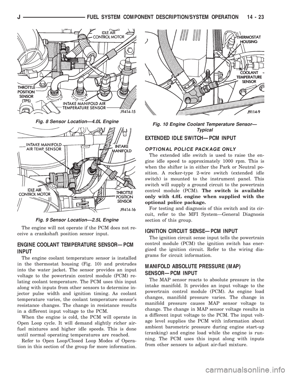
The engine coolant temperature sensor is installed
in the thermostat housing (Fig. 10) and protrudes
into the water jacket. The sensor provides an input
voltage to the powertrain control module (PCM) re-
lating coolant temperature. The PCM uses this input
along with inputs from other sensors to determine in-
jector pulse width and ignition timing. As coolant
temperature varies, the coolant temperature sensor's
resistance changes. The change in resistance results
in a different input voltage to the PCM.
When the engine is cold, the PCM will operate in
Open Loop cycle. It will demand slightly richer air-
fuel mixtures and higher idle speeds. This is done
until normal operating temperatures are reached.
Refer to Open Loop/Closed Loop Modes of Opera-
tion in this section of the group for more information.
EXTENDED IDLE SWITCHÐPCM INPUT
OPTIONAL POLICE PACKAGE ONLY
The extended idle switch is used to raise the en-
gine idle speed to approximately 1000 rpm. This is
when the shifter is in either the Park or Neutral po-
sition. A rocker-type 2-wire switch (extended idle
switch) is mounted to the instrument panel. This
switch will supply a ground circuit to the powertrain
control module (PCM).The switch is available
only with 4.0L engine when supplied with the
optional police package.
For testing and diagnosis of this switch and its cir-
cuit, refer to the MFI SystemÐGeneral Diagnosis
section of this group.
IGNITION CIRCUIT SENSEÐPCM INPUT
The ignition circuit sense input tells the powertrain
control module (PCM) the ignition switch has ener-
gized the ignition circuit. Refer to the wiring dia-
grams for circuit information.
MANIFOLD ABSOLUTE PRESSURE (MAP)
SENSORÐPCM INPUT
The MAP sensor reacts to absolute pressure in the
intake manifold. It provides an input voltage to the
powertrain control module (PCM). As engine load
changes, manifold pressure varies. The change in
manifold pressure causes MAP sensor voltage to
change. The change in MAP sensor voltage results in
a different input voltage to the PCM. The input volt-
age level supplies the PCM with information about
ambient barometric pressure during engine start-up
(cranking) and engine load while the engine is run-
ning. The PCM uses this input along with inputs
from other sensors to adjust air-fuel mixture.
Fig. 8 Sensor LocationÐ4.0L Engine
Fig. 9 Sensor LocationÐ2.5L Engine
Fig. 10 Engine Coolant Temperature SensorÐ
Typical
JFUEL SYSTEM COMPONENT DESCRIPTION/SYSTEM OPERATION 14 - 23
Page 1246 of 2198
²The powertrain control module (PCM) pre-posi-
tions the idle air control (IAC) motor.
²The PCM determines atmospheric air pressure
from the MAP sensor input to determine basic fuel
strategy.
²The PCM monitors the engine coolant temperature
sensor input. The PCM modifies fuel strategy based
on this input.
²Intake manifold air temperature sensor input is
monitored
²Throttle position sensor (TPS) is monitored
²The auto shutdown (ASD) relay is energized by the
PCM for approximately three seconds.
²The fuel pump is energized through the fuel pump
relay by the PCM. The fuel pump will operate for ap-
proximately three seconds unless the engine is oper-
ating or the starter motor is engaged
²The O2S sensor heater element is energized
through the fuel pump relay. The O2S sensor input is
not used by the PCM to calibrate air-fuel ratio dur-
ing this mode of operation.
²The up-shift indicator lamp is illuminated (manual
transmission only).
ENGINE START-UP MODE
This is an Open Loop mode. The following actions
occur when the starter motor is engaged.
The powertrain control module (PCM) receives in-
puts from:
²Battery voltage
²Engine coolant temperature sensor
²Crankshaft position sensor
²Intake manifold air temperature sensor
²Manifold absolute pressure (MAP) sensor
²Throttle position sensor (TPS)
²Starter motor relay
²Camshaft position sensor signal
The PCM monitors the crankshaft position sensor.
If the PCM does not receive a crankshaft position
sensor signal within 3 seconds of cranking the en-
gine, it will shut down the fuel injection system.
The fuel pump is activated by the PCM through
the fuel pump relay.
Voltage is applied to the fuel injectors with the
PCM. The PCM will then control the injection se-
quence and injector pulse width by turning the
ground circuit to each individual injector on and off.
The PCM determines the proper ignition timing ac-
cording to input received from the crankshaft posi-
tion sensor.
ENGINE WARM-UP MODE
This is an Open Loop mode. During engine warm-
up, the powertrain control module (PCM) receives in-
puts from:
²Battery voltage
²Crankshaft position sensor
²Engine coolant temperature sensor²Intake manifold air temperature sensor
²Manifold absolute pressure (MAP) sensor
²Throttle position sensor (TPS)
²Camshaft position sensor signal (in the distribu-
tor)
²Park/neutral switch (gear indicator signalÐauto.
trans. only)
²Air conditioning select signal (if equipped)
²Air conditioning request signal (if equipped)
Based on these inputs the following occurs:
²Voltage is applied to the fuel injectors with the
powertrain control module (PCM). The PCM will
then control the injection sequence and injector pulse
width by turning the ground circuit to each individ-
ual injector on and off.
²The PCM adjusts engine idle speed through the
idle air control (IAC) motor and adjusts ignition tim-
ing.
²The PCM operates the A/C compressor clutch
through the clutch relay. This is done if A/C has been
selected by the vehicle operator and requested by the
A/C thermostat.
²If the vehicle has a manual transmission, the up-
shift lamp is operated by the PCM.
²When engine has reached operating temperature,
the PCM will begin monitoring O2S sensor input.
The system will then leave the warm-up mode and go
into closed loop operation.
IDLE MODE
When the engine is at operating temperature, this
is a Closed Loop mode. At idle speed, the powertrain
control module (PCM) receives inputs from:
²Air conditioning select signal (if equipped)
²Air conditioning request signal (if equipped)
²Battery voltage
²Crankshaft position sensor
²Engine coolant temperature sensor
²Intake manifold air temperature sensor
²Manifold absolute pressure (MAP) sensor
²Throttle position sensor (TPS)
²Camshaft position sensor signal (in the distribu-
tor)
²Battery voltage
²Park/neutral switch (gear indicator signalÐauto.
trans. only)
²Oxygen sensor
Based on these inputs, the following occurs:
²Voltage is applied to the fuel injectors with the
powertrain control module (PCM). The PCM will
then control injection sequence and injector pulse
width by turning the ground circuit to each individ-
ual injector on and off.
²The PCM monitors the O2S sensor input and ad-
justs air-fuel ratio by varying injector pulse width. It
also adjusts engine idle speed through the idle air
control (IAC) motor.
JFUEL SYSTEM COMPONENT DESCRIPTION/SYSTEM OPERATION 14 - 31
Page 1247 of 2198
²The PCM adjusts ignition timing by increasing
and decreasing spark advance.
²The PCM operates the A/C compressor clutch
through the clutch relay. This happens if A/C has
been selected by the vehicle operator and requested
by the A/C thermostat.
The optional Extended Idle Switch is used to raise
the engine idle speed to approximately 1000 rpm.
This is when the shifter is in either the Park or Neu-
tral position. A rocker-type 2-wire switch (extended
idle switch) is mounted to the instrument panel. This
switch will supply a ground circuit to the powertrain
control module (PCM).The switch is available
only with 4.0L engine when supplied with the
optional police package.
CRUISE MODE
When the engine is at operating temperature, this
is a Closed Loop mode. At cruising speed, the power-
train control module (PCM) receives inputs from:
²Air conditioning select signal (if equipped)
²Air conditioning request signal (if equipped)
²Battery voltage
²Engine coolant temperature sensor
²Crankshaft position sensor
²Intake manifold air temperature sensor
²Manifold absolute pressure (MAP) sensor
²Throttle position sensor (TPS)
²Camshaft position sensor signal (in the distribu-
tor)
²Park/neutral switch (gear indicator signalÐauto.
trans. only)
²Oxygen (O2S) sensor
Based on these inputs, the following occurs:
²Voltage is applied to the fuel injectors with the
PCM. The PCM will then adjust the injector pulse
width by turning the ground circuit to each individ-
ual injector on and off.
²The PCM monitors the O2S sensor input and ad-
justs air-fuel ratio. It also adjusts engine idle speed
through the idle air control (IAC) motor.
²The PCM adjusts ignition timing by turning the
ground path to the coil on and off.
²The PCM operates the A/C compressor clutch
through the clutch relay. This happens if A/C has
been selected by the vehicle operator and requested
by the A/C thermostat.
ACCELERATION MODE
This is an Open Loop mode. The powertrain control
module (PCM) recognizes an abrupt increase in
throttle position or MAP pressure as a demand for
increased engine output and vehicle acceleration. The
PCM increases injector pulse width in response to in-
creased throttle opening.
DECELERATION MODE
When the engine is at operating temperature, this
is an Open Loop mode. During hard deceleration, the
powertrain control module (PCM) receives the follow-
ing inputs.
²Air conditioning select signal (if equipped)
²Air conditioning request signal (if equipped)
²Battery voltage
²Engine coolant temperature sensor
²Crankshaft position sensor
²Intake manifold air temperature sensor
²Manifold absolute pressure (MAP) sensor
²Throttle position sensor (TPS)
²Camshaft position sensor signal (in the distribu-
tor)
²Park/neutral switch (gear indicator signalÐauto.
trans. only)
If the vehicle is under hard deceleration with the
proper rpm and closed throttle conditions, the PCM
will ignore the oxygen sensor input signal. The PCM
will enter a fuel cut-off strategy in which it will not
supply battery voltage to the injectors. If a hard de-
celeration does not exist, the PCM will determine the
proper injector pulse width and continue injection.
Based on the above inputs, the PCM will adjust en-
gine idle speed through the idle air control (IAC) mo-
tor.
The PCM adjusts ignition timing by turning the
ground path to the coil on and off.
The PCM opens the ground circuit to the A/C
clutch relay to disengage the A/C compressor clutch.
This is done until the vehicle is no longer under de-
celeration (if the A/C system is operating).
WIDE OPEN THROTTLE MODE
This is an Open Loop mode. During wide open
throttle operation, the powertrain control module
(PCM) receives the following inputs.
²Battery voltage
²Crankshaft position sensor
²Engine coolant temperature sensor
²Intake manifold air temperature sensor
²Manifold absolute pressure (MAP) sensor
²Throttle position sensor (TPS)
²Camshaft position sensor signal (in the distribu-
tor)
During wide open throttle conditions, the following
occurs:
²Voltage is applied to the fuel injectors with the
powertrain control module (PCM). The PCM will
then control the injection sequence and injector pulse
width by turning the ground circuit to each individ-
ual injector on and off. The PCM ignores the oxygen
sensor input signal and provides a predetermined
amount of additional fuel. This is done by adjusting
injector pulse width.
²The PCM adjusts ignition timing by turning the
ground path to the coil on and off.
14 - 32 FUEL SYSTEM COMPONENT DESCRIPTION/SYSTEM OPERATIONJ
Page 1270 of 2198
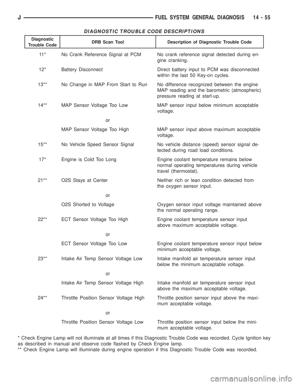
DIAGNOSTIC TROUBLE CODE DESCRIPTIONS
Diagnostic
Trouble CodeDRB Scan Tool Description of Diagnostic Trouble Code
11* No Crank Reference Signal at PCM No crank reference signal detected during en-
gine cranking.
12* Battery Disconnect Direct battery input to PCM was disconnected
within the last 50 Key-on cycles.
13** No Change in MAP From Start to Run No difference recognized between the engine
MAP reading and the barometric (atmospheric)
pressure reading at start-up.
14** MAP Sensor Voltage Too Low MAP sensor input below minimum acceptable
voltage.
or
MAP Sensor Voltage Too High MAP sensor input above maximum acceptable
voltage.
15** No Vehicle Speed Sensor Signal No vehicle distance (speed) sensor signal de-
tected during road load conditions.
17* Engine is Cold Too Long Engine coolant temperature remains below
normal operating temperatures during vehicle
travel (thermostat).
21** O2S Stays at Center Neither rich or lean condition detected from
the oxygen sensor input.
or
O2S Shorted to Voltage Oxygen sensor input voltage maintained above
the normal operating range.
22** ECT Sensor Voltage Too High Engine coolant temperature sensor input
above maximum acceptable voltage.
or
ECT Sensor Voltage Too Low Engine coolant temperature sensor input below
minimum acceptable voltage.
23** Intake Air Temp Sensor Voltage Low Intake manifold air temperature sensor input
below the minimum acceptable voltage.
or
Intake Air Temp Sensor Voltage High Intake manifold air temperature sensor input
above the maximum acceptable voltage.
24** Throttle Position Sensor Voltage High Throttle position sensor input above the maxi-
mum acceptable voltage.
or
Throttle Position Sensor Voltage Low Throttle position sensor input below the mini-
mum acceptable voltage.
* Check Engine Lamp will not illuminate at all times if this Diagnostic Trouble Code was recorded. Cycle Ignition key
as described in manual and observe code flashed by Check Engine lamp.
** Check Engine Lamp will illuminate during engine operation if this Diagnostic Trouble Code was recorded.
JFUEL SYSTEM GENERAL DIAGNOSIS 14 - 55
Page 1275 of 2198
CAMSHAFT POSITION SENSOR
For removal/installation procedures, refer to Group
8D, Ignition System. See Camshaft Position Sensor.
INTAKE MANIFOLD AIR TEMPERATURE SENSOR
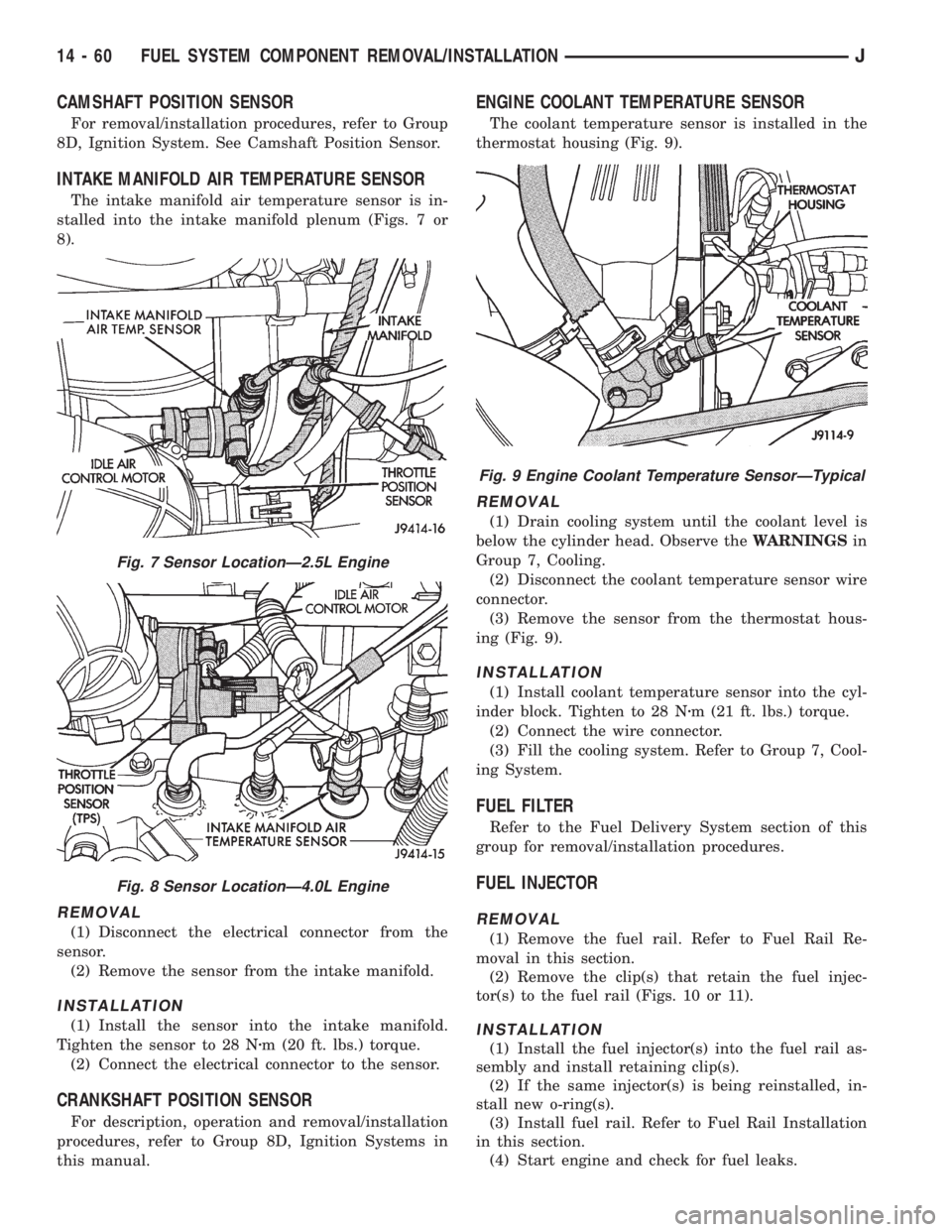
The intake manifold air temperature sensor is in-
stalled into the intake manifold plenum (Figs. 7 or
8).
REMOVAL
(1) Disconnect the electrical connector from the
sensor.
(2) Remove the sensor from the intake manifold.
INSTALLATION
(1) Install the sensor into the intake manifold.
Tighten the sensor to 28 Nzm (20 ft. lbs.) torque.
(2) Connect the electrical connector to the sensor.
CRANKSHAFT POSITION SENSOR
For description, operation and removal/installation
procedures, refer to Group 8D, Ignition Systems in
this manual.
ENGINE COOLANT TEMPERATURE SENSOR
The coolant temperature sensor is installed in the
thermostat housing (Fig. 9).
REMOVAL
(1) Drain cooling system until the coolant level is
below the cylinder head. Observe theWARNINGSin
Group 7, Cooling.
(2) Disconnect the coolant temperature sensor wire
connector.
(3) Remove the sensor from the thermostat hous-
ing (Fig. 9).
INSTALLATION
(1) Install coolant temperature sensor into the cyl-
inder block. Tighten to 28 Nzm (21 ft. lbs.) torque.
(2) Connect the wire connector.
(3) Fill the cooling system. Refer to Group 7, Cool-
ing System.
FUEL FILTER
Refer to the Fuel Delivery System section of this
group for removal/installation procedures.
FUEL INJECTOR
REMOVAL
(1) Remove the fuel rail. Refer to Fuel Rail Re-
moval in this section.
(2) Remove the clip(s) that retain the fuel injec-
tor(s) to the fuel rail (Figs. 10 or 11).
INSTALLATION
(1) Install the fuel injector(s) into the fuel rail as-
sembly and install retaining clip(s).
(2) If the same injector(s) is being reinstalled, in-
stall new o-ring(s).
(3) Install fuel rail. Refer to Fuel Rail Installation
in this section.
(4) Start engine and check for fuel leaks.
Fig. 7 Sensor LocationÐ2.5L Engine
Fig. 8 Sensor LocationÐ4.0L Engine
Fig. 9 Engine Coolant Temperature SensorÐTypical
14 - 60 FUEL SYSTEM COMPONENT REMOVAL/INSTALLATIONJ
Page 1902 of 2198
EVAPORATOR COIL:The coil is located in the
A/C housing. Its function is to remove heat and de-
humidify the air before it enters the vehicle.
FIN SENSING CYCLING CLUTCH SWITCH:
The switch is attached to the evaporator coil with the
temperature sensing probe inserted into the coil fins.
This switch controls evaporator temperature and pre-
vents condensate water on the evaporator coil from
freezing. It does this by sending signals to the Pow-
ertrain Control Module (PCM) to cycling the com-
pressor clutch on and off. This switch is used onXJ
only.
FILTER-DRIER:The drier is used to remove any
traces of moisture from the refrigerant system. A
sight glass is located on top of the filter drier. It is
used as a diagnostic tool to observe refrigerant flow.
HIGH PRESSURE RELIEF VALVE:The valve is
located on the filter drier. The valve is used to pre-
vent excessive high pressure build of 3445 to 4135
kPa (500 to 600 psi) and above. This prevents dam-
age to the compressor and other system components.
LOW-PRESSURE HIGH-PRESSURE CUT-OFF
SWITCH:The switch is located on the filter drier
and is wired in series with compressor clutch. When
the pressure drops down to 193 kPa (28 psi) the
switch interrupts the power to the compressor clutch.
When the pressure increases above 3100 to 3375 kPa
(450 to 490 psi) the switch interrupts the power to
the compressor clutch.
THERMOSTAT:The thermostat is located in the
evaporator housing. The thermostat temperature
sensing probe is inserted into the evaporator coil. Its
function is to cycles the compressor clutch on and off.
This switch controls temperature and prevents con-
densate water on the evaporator coil from freezing.
The thermostat is used on theYJonly.
REFRIGERANT LINES:The lines are used to
carry the refrigerant between the various system
components.
SERVICE PORTS:The high pressure service port
is located on the discharge line near the compressor.
The low pressure service port is located on the suc-
tion line near the compressor. These ports are used
to attach A/C gauges. After servicing the refrigerant
system, always install service port caps.
REFRIGERANT
XJ and YJ vehicles use a new type of refrigerant
called R-134a. It is a non-toxic, non-flammable, clear
color-less liquified gas.
R-134a refrigerant is not compatible with R-12 re-
frigerant. A small amount of R-12 in a R-134a system
will cause compressor failure, oil sludge or poor air
conditioning performance.R-134a refrigerant requires a special type of com-
pressor oil (SP20 PAG). When adding oil, make sure
that it is designed to be used in a R-134a system and
the SD7H15 compressor.
Service ports have been designed to ensure that
the system is not accidentally filled with R-12 refrig-
erant.
REFRIGERANT EQUIPMENT
WARNING: EYE PROTECTION MUST BE USED
WHEN SERVICING AN AIR CONDITIONING REFRIG-
ERANT SYSTEM. TURN OFF (ROTATE CLOCKWISE)
ALL VALVES ON THE EQUIPMENT BEING USED
BEFORE PROCEEDING WITH THIS OPERATION.
PERSONNEL INJURY CAN RESULT.
Chrysler Corporation recommends a (R-134a) recy-
cling device that meets SAE standard J2210 be used
when servicing the refrigerant system. Contact an
automotive service equipment supplier for refrigerant
recycling equipment that is available in your area.
Refer to the operating instructions provided with the
recycling equipment for proper operation.
MANIFOLD GAUGE SET
CAUTION: DO NOT use an R-12 manifold gauge set
on an R-134a system. The refrigerants are not com-
patible and system damage will result.
A manifold gauge set (Fig. 1) may be needed in
conjunction with the charging and or recovery/recy-
cling device. The service hoses on the gauge set being
used should have manual (turn wheel) or automatic
back flow valves at the service port connector ends.
This will prevent refrigerant from being release into
the atmosphere.
LOW PRESSURE GAUGE HOSE
The low pressure hose (BLUE with BLACK STRIP)
should be attached to the charging/service port. This
port is located at the right front of the engine com-
partment in the condenser-to-evaporator line.
HIGH PRESSURE GAUGE HOSE
The high pressure hose (RED with BLACK STRIP)
should be attached to the discharge/service port. This
port is located on the compressor plumbing or mani-
fold.
RECOVERY/RECYCLING/EVACUATION/
CHARGING HOSE
The center manifold hose (YELLOW or WHITE
with BLACK STRIP) is used to recover, evacuate and
charge the refrigerant system. When the low or high
pressure valves on the manifold gauge set are
opened, the refrigerant in the system will escape
through this hose.
JHEATING AND AIR CONDITIONING 24 - 7
Page 1910 of 2198
HEATING AND AIR CONDITIONING TEST PROCEDURES
INDEX
page page
A/C Compressor Clutch..................... 15
A/C Compressor Clutch Relay................ 15
A/C Compressor Clutch Relay................ 16
Air Conditioning ControlsÐXJ Vehicles......... 15
Air Conditioning ControlsÐYJ Vehicles......... 16
Blower Motor............................ 17
Blower Motor Switch....................... 16Compressor Clutch........................ 16
Fin Sensing Cycling Clutch Switch............. 15
Heater Diagnosis......................... 17
Low-Pressure High-Pressure Cut-Off Switch..... 15
Low-Pressure High-Pressure Cut-Off Switch..... 16
Thermostatic Control....................... 16
AIR CONDITIONING CONTROLSÐXJ VEHICLES
The A/C Compressor Clutch is controlled by several
components: the Pressure Cut-Off Switch, Cycling
Clutch Switch, Clutch Relay and Powertrain Control
Module (PCM).
Powertrain Control Module may delay A/C clutch
engagement up to 30 seconds.
Refer to Group 8W Wiring Diagrams for wiring and
terminals. Use volt ohmmeter to test switches.
A/C COMPRESSOR CLUTCH
The clutch assembly consists of a stationary elec-
tromagnetic coil, hub bearing pulley assembly, and
clutch plate. When the coil is energized the plate is
magnetically engaged with the pulley and turns the
compressor shaft.
A/C COMPRESSOR CLUTCH TEST
(1) Unplug clutch coil connector.
(2) Connect a jumper wire from the battery posi-
tive post to the clutch coil terminal. The clutch
should engage, if not leave jumper wire connected
and go to next step.
(3) Connect a jumper wire from clutch coil frame to
chassis ground. The clutch should engage if not re-
pair clutch coil ground or replace coil.
A/C COMPRESSOR CLUTCH RELAY
The A/C compressor clutch relay controls the 12-
volt source to the A/C clutch. The relay is activated
when the PCM receives a A/C request signal from the
fin-sensed cycling clutch switch. The PCM then sends
a ground signal to the relay. The relay is activated
and sends 12-volts to the clutch coil which energizes
the clutch. The relay is located in the power distribu-
tion center.
COMPRESSOR CLUTCH RELAY TEST
For test procedure refer to Powertrain Diagnostic
Service Manual for A/C clutch relay circuit test.
LOW-PRESSURE HIGH-PRESSURE CUT-OFF
SWITCH
The pressure cut-off switch is located on the filter
drier and is wired in series with compressor clutch.
The switch interrupts the power to the compressor
clutch circuit when the pressure drops to 193 kPa (28
psi) or increases above 3100 to 3375 kPa (450 to 490
psi).
PRESSURE CUT-OFF SWITCH TEST
(1) Verify system has correct refrigerant charge.
(2) Turn ignition switch to RUN, A/C blower switch
to ON and control set to MAX.
(3) Unplug pressure cut-off switch and test feed
circuit from select switch. It should be battery volt-
age if not, repair open to select switch.
(4) Test for continuity between the switch termi-
nals. If continuity is not present recover refrigerant
from the system. Replace switch, evacuate and re-
charge system.
FIN SENSING CYCLING CLUTCH SWITCH
The switch is attached to the evaporator coil with
the temperature sensing probe inserted into the coil
fins. This switch prevents condensate water on the
evaporator coil from freezing. It does this by sending
signals to the PCM to cycling the compressor clutch
on and off.
FIN-SENSED CYCLING CLUTCH SWITCH TEST
Test area ambient temperature should be around
21ÉC (70ÉF) for test.
(1) Verify system has correct refrigerant charge.
(2) Start Engine and turn on A/C.
(3) If the compressor clutch cycles ON and OFF 2
to 3 times per minute the cycling clutch switch is
normal. The ambient temperature should be between
20ÉC-30ÉC (68ÉF-90ÉF). Above 32ÉC (90ÉF) the com-
pressor clutch may stay engaged (non cycling) due to
the high heat load, this condition is normal. If the
compressor clutch fails to engage go to next step.
(4) Disconnect wiring harness connector from
switch. With a volt meter test feed circuit from cut-
JHEATING AND AIR CONDITIONING 24 - 15