heating JEEP CHEROKEE 1995 Service Repair Manual
[x] Cancel search | Manufacturer: JEEP, Model Year: 1995, Model line: CHEROKEE, Model: JEEP CHEROKEE 1995Pages: 2198, PDF Size: 82.83 MB
Page 33 of 2198
(2) Note any indication of drum/rotor overheating,
wheel dragging or the vehicle pulling to one side
when the brakes are applied.
(3) Evaluate any performance complaints received
from the owner/operator.
(4) Repair the brake system as necessary. Refer to
Group, 5 Brakes for additional information and ser-
vice procedures.
TIRES
RECOMMENDED MAINTENANCE
The general condition of the tires and the inflation
pressures should be inspected at the same time the
engine oil is changed and the oil filter is replaced.
In addition, the tires/wheels should be rotated at
the intervals described in the Maintenance Schedules
section of this group.
INSPECTION
Inspect the tires for excessive wear, damage, etc.
Test the tires for the recommended inflation pres-sure. Refer to the tire inflation pressure decal located
on the inside of the glove box door, and also to Group
22, Tires And Wheels.
ROTATION
Refer to Group 22, Tires And Wheels for the recom-
mended method of tire/wheel rotation for a Jeep ve-
hicle.
BODY COMPONENTS
LUBRICATION REQUIREMENTS
All Jeep operating mechanisms and linkages
should be lubricated when necessary. The door
weatherstrip seals should be lubricated to prolong
their life as well as to improve door sealing.
LUBRICANT SPECIFICATIONS
All applicable exterior and interior vehicle operat-
ing mechanisms should be:
²Inspected
²Cleaned
²Pivot/sliding contact areas on the mechanisms
should then be lubricated.
Multi-purpose NLGI GC-LB MOPAR Multi-Mileage
Lubricant or an equivalent, should be used to lubri-
cate the mechanisms. The door weatherstrip seals
should be lubricated with silicone lubricant spray.
Refer to the Body Lubricant Specifications chart be-
low for additional lubricant applications.
LUBRICATION
All pivoting and sliding contact areas, should be lu-
bricated periodically to ensure quiet, easy operation
and to protect against wear and corrosion. Areas in-
clude:
²Seat tracks.
²Door hinges/latches/strikers.
²Liftgate/tailgate/hood hinges (Fig. 11).
(1) As required, lubricate the body components
with the specified lubricants.
(2) Apply silicone lubricant to a cloth and wipe it
on door seals to avoid over-spray that can soil pas-
senger clothing.
(3) Before applying lubricant, the component
should be wiped clean. After lubrication, any excess
lubricant should be removed.
(4) The door lock cylinders should be lubricated 2
times each year (preferably autumn and spring):
²Spray a small amount of lock cylinder lubricant di-
rectly into the lock cylinder.
²Apply a small amount to the key and insert it into
the lock cylinder.
²Rotate it to the locked position and then back to
the unlocked position several times.
²Remove the key. Wipe the lubricant from it with a
clean cloth to avoid soiling of clothing.
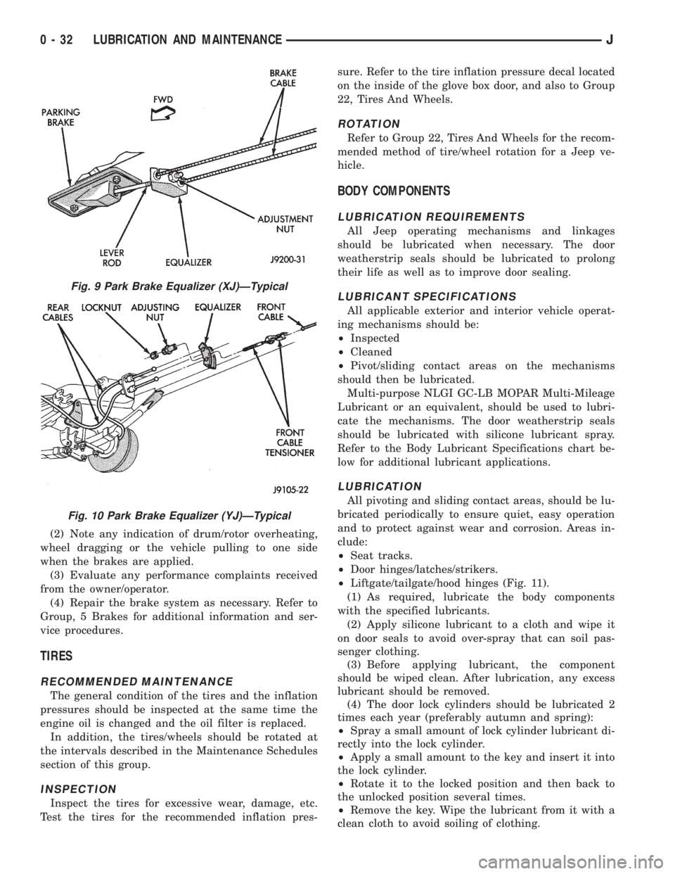
Fig. 9 Park Brake Equalizer (XJ)ÐTypical
Fig. 10 Park Brake Equalizer (YJ)ÐTypical
0 - 32 LUBRICATION AND MAINTENANCEJ
Page 41 of 2198
even tire wear. The wheel toe position is thefinal
front wheel alignment adjustment.
²STEERING AXIS INCLINATION ANGLE is mea-
sured in degrees and is the angle that the steering
knuckles are tilted (Fig. 1). The inclination angle has
a fixed relationship with the camber angle. It will not
change except when a spindle or ball stud is dam-
aged or bent. The angle is not adjustable, the dam-
aged component(s) must be replaced to correct mis-
alignment.
WARNING: DO NOT ATTEMPT TO MODIFY ANY
SUSPENSION OR STEERING COMPONENT BY
HEATING AND BENDING.
PRE-ALIGNMENT INSPECTION
Before starting a front wheel alignment, the follow-
ing inspection and necessary corrections must be
completed.(1) Tires with the same recommended air pressure,
size, and thread wear. Refer to Group 22, Tires And
Wheels for diagnosis information.
(2) Front wheel bearings for wear and looseness.
(3) Ball studs, steering linkage pivot points and
steering gear for looseness, roughness, binding or
wear. Refer to Group 19, Steering for additional in-
formation.
(4) Front wheels for excessive radial or lateral
runout and unbalance. Refer to Group 22, Tires And
Wheels for diagnosis information.
(5) Suspension components for wear. Check compo-
nents for correct torque. Refer to Groups 2 and 3,
Suspension and Axle for additional information.
2 - 6 FRONT SUSPENSION AND AXLEJ
Page 53 of 2198
AXLE NOISE/VIBRATION DIAGNOSIS
INDEX
page page
Driveline Snap........................... 19
Gear and Bearing Noise.................... 18
General Information....................... 18Low Speed Knock......................... 19
Vibration................................ 19
GENERAL INFORMATION
Axle bearing problem conditions are usually caused
by:
²Insufficient or incorrect lubricant
²Foreign matter/water contamination
²Incorrect bearing preload torque adjustment
²Incorrect backlash (to tight)
When serviced, the bearings must be cleaned thor-
oughly. They should be dried with lint-free shop tow-
els.Never dry bearings with compressed air.
This will overheat them and brinell the bearing
surfaces. This will result in noisy operation af-
ter repair.
Axle gear problem conditions are usually the result
of:
²Insufficient lubrication
²Incorrect or contaminated lubricant
²Overloading (excessive engine torque) or exceeding
vehicle weight capacity
²Incorrect clearance or backlash adjustment
Insufficient lubrication is usually the result of a
housing cover leak. It can also be from worn axle
shaft or pinion gear seals. Check for cracks or porous
areas in the housing or tubes.
Using the wrong lubricant will cause overheating
and gear failure. Gear tooth cracking and bearing
spalling are indicators of this.
Axle component breakage is most often the result
of:
²Severe overloading
²Insufficient lubricant
²Incorrect lubricant
²Improperly tightened components
Overloading occurs when towing heavier than rec-
ommended loads. Component breakage can occur
when the wheels are spun excessively. Incorrect lu-
bricant quantity contributes to breakage. Loose dif-
ferential components can also cause breakage.
Incorrect bearing preload or gear backlash will not
result in component breakage. Mis-adjustment will
produce enough noise to cause service repair before a
failure occurs. If a mis-adjustment condition is not
corrected, component failure can result.
Excessive bearing preload may not be noisy. This
condition will cause high temperature which can re-
sult in bearing failure.
GEAR AND BEARING NOISE
GEAR NOISE
Axle gear noise can be caused by insufficient lubri-
cant. Incorrect backlash, tooth contact, or worn/dam-
aged gears can cause noise.
Gear noise usually happens at a specific speed
range. The range is 30 to 40 mph, or above 50 mph.
The noise can also occur during a specific type of
driving condition. These conditions are acceleration,
deceleration, coast, or constant load.
When road testing, accelerate the vehicle to the
speed range where the noise is the greatest. Shift
out-of-gear and coast through the peak-noise range.
If the noise stops or changes greatly, check for insuf-
ficient lubricant. Incorrect ring gear backlash, or
gear damage can cause noise changes.
Differential side and pinion gears can be checked
by turning the vehicle. They usually do not cause
noise in straight-ahead driving. These gears are
loaded during vehicle turns. If noise does occur dur-
ing vehicle turns, the side or pinion gears could be
worn or damaged. A worn pinion gear mate shaft can
also cause a snapping or a knocking noise.
BEARING NOISE
The axle shaft, differential and pinion gear bear-
ings can all produce noise when worn or damaged.
Bearing noise can be either a whining, or a growling
sound.
Pinion gear bearings have a constant-pitch noise.
This noise changes only with vehicle speed. Pinion
bearing noise will be higher because it rotates at a
faster rate. Drive the vehicle and load the differen-
tial. If bearing noise occurs the pinion rear bearing is
the source of the noise. If the bearing noise is heard
during a coast, front bearing is the source.
Worn, damaged differential bearings usually pro-
duce a low pitch noise. Differential bearing noise is
similar to pinion bearing. The pitch of differential
bearing noise is also constant and varies only with
vehicle speed.
2 - 18 FRONT SUSPENSION AND AXLEJ
Page 81 of 2198
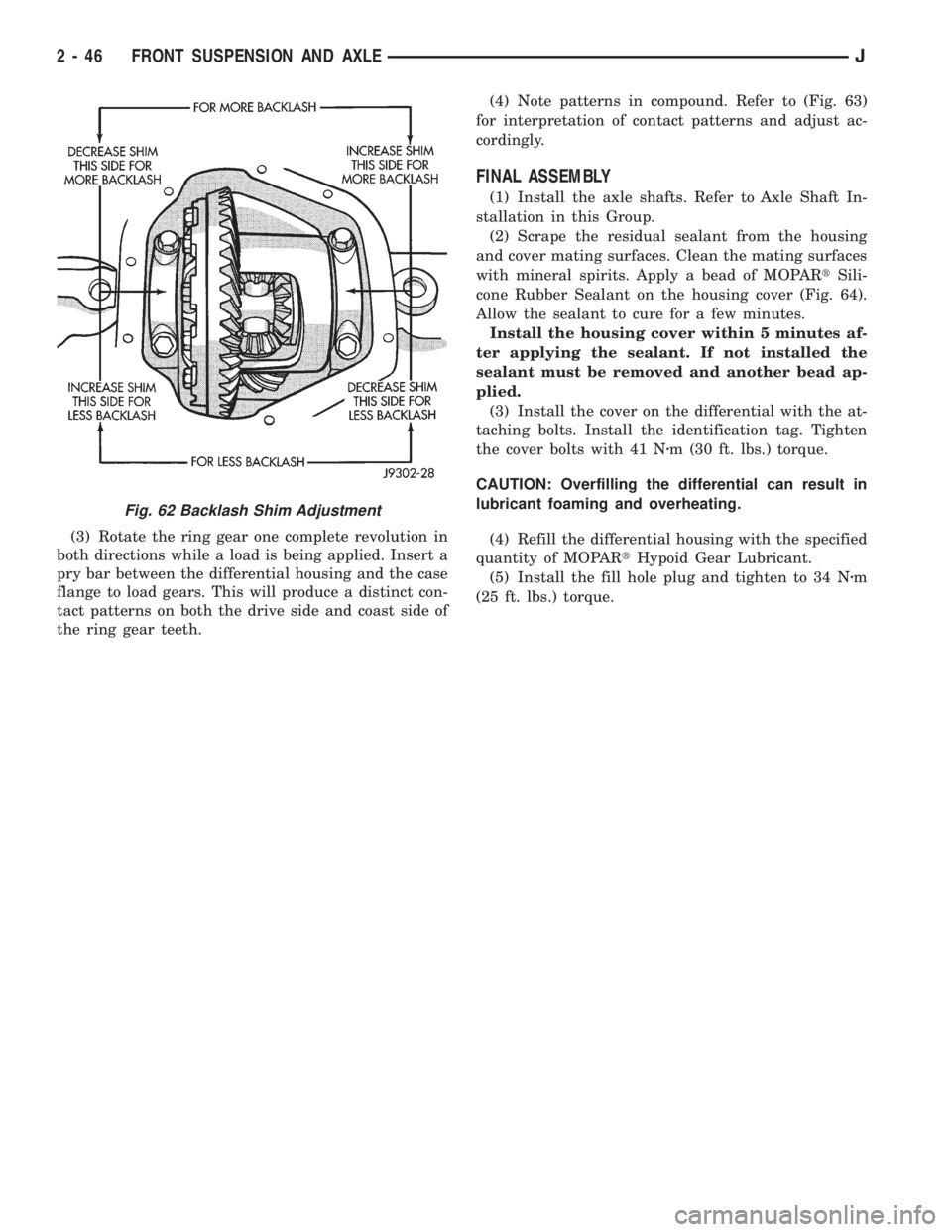
(3) Rotate the ring gear one complete revolution in
both directions while a load is being applied. Insert a
pry bar between the differential housing and the case
flange to load gears. This will produce a distinct con-
tact patterns on both the drive side and coast side of
the ring gear teeth.(4) Note patterns in compound. Refer to (Fig. 63)
for interpretation of contact patterns and adjust ac-
cordingly.
FINAL ASSEMBLY
(1) Install the axle shafts. Refer to Axle Shaft In-
stallation in this Group.
(2) Scrape the residual sealant from the housing
and cover mating surfaces. Clean the mating surfaces
with mineral spirits. Apply a bead of MOPARtSili-
cone Rubber Sealant on the housing cover (Fig. 64).
Allow the sealant to cure for a few minutes.
Install the housing cover within 5 minutes af-
ter applying the sealant. If not installed the
sealant must be removed and another bead ap-
plied.
(3) Install the cover on the differential with the at-
taching bolts. Install the identification tag. Tighten
the cover bolts with 41 Nzm (30 ft. lbs.) torque.
CAUTION: Overfilling the differential can result in
lubricant foaming and overheating.
(4) Refill the differential housing with the specified
quantity of MOPARtHypoid Gear Lubricant.
(5) Install the fill hole plug and tighten to 34 Nzm
(25 ft. lbs.) torque.
Fig. 62 Backlash Shim Adjustment
2 - 46 FRONT SUSPENSION AND AXLEJ
Page 94 of 2198
AXLE NOISE/VIBRATION DIAGNOSIS
INDEX
page page
Driveline Snap........................... 10
Gear and Bearing Noise..................... 9
General Information........................ 9
Limited Slip Differential..................... 10Low Speed Knock......................... 10
Rear Axle Alignment....................... 10
Vibration................................ 10
GENERAL INFORMATION
Axle bearing problem conditions are usually caused
by:
²Insufficient or incorrect lubricant
²Foreign matter/water contamination
²Incorrect bearing preload torque adjustment
²Incorrect backlash (to tight)
When serviced, the bearings must be cleaned thor-
oughly. They should be dried with lint-free shop tow-
els.Never dry bearings with compressed air.
This will overheat them and brinell the bearing
surfaces. This will result in noisy operation af-
ter repair.
Axle gear problem conditions are usually the result of:
²Insufficient lubrication
²Incorrect or contaminated lubricant
²Overloading (excessive engine torque) or exceeding
vehicle weight capacity
²Incorrect clearance or backlash adjustment
Insufficient lubrication is usually the result of a
housing cover leak. It can also be from worn axle
shaft or pinion gear seals. Check for cracks or porous
areas in the housing or tubes.
Using the wrong lubricant will cause overheating
and gear failure. Gear tooth cracking and bearing
spalling are indicators of this.
Axle component breakage is most often the result of:
²Severe overloading
²Insufficient lubricant
²Incorrect lubricant
²Improperly tightened components
Overloading occurs when towing heavier than rec-
ommended loads. Component breakage can occur
when the wheels are spun excessively. Incorrect lu-
bricant quantity contributes to breakage. Loose dif-
ferential components can also cause breakage.
Incorrect bearing preload or gear backlash will not
result in component breakage. Mis-adjustment will
produce enough noise to cause service repair before a
failure occurs. If a mis-adjustment condition is not
corrected, component failure can result.
Excessive bearing preload may not be noisy. This
condition will cause high temperature which can re-
sult in bearing failure.
GEAR AND BEARING NOISE
GEAR NOISE
Axle gear noise can be caused by insufficient lubri-
cant. Incorrect backlash, tooth contact, or worn/dam-
aged gears can cause noise.
Gear noise usually happens at a specific speed
range. The range is 30 to 40 mph, or above 50 mph.
The noise can also occur during a specific type of
driving condition. These conditions are acceleration,
deceleration, coast, or constant load.
When road testing, accelerate the vehicle to the
speed range where the noise is the greatest. Shift
out-of-gear and coast through the peak-noise range.
If the noise stops or changes greatly, check for insuf-
ficient lubricant. Incorrect ring gear backlash, or
gear damage can cause noise changes.
Differential side and pinion gears can be checked
by turning the vehicle. They usually do not cause
noise in straight-ahead driving. These gears are
loaded during vehicle turns. If noise does occur dur-
ing vehicle turns, the side or pinion gears could be
worn or damaged. A worn pinion gear mate shaft can
also cause a snapping or a knocking noise.
BEARING NOISE
The axle shaft, differential and pinion gear bear-
ings can all produce noise when worn or damaged.
Bearing noise can be either a whining, or a growling
sound.
Pinion gear bearings have a constant-pitch noise.
This noise changes only with vehicle speed. Pinion
bearing noise will be higher because it rotates at a
faster rate. Drive the vehicle and load the differen-
tial. If bearing noise occurs the pinion rear bearing is
the source of the noise. If the bearing noise is heard
during a coast, front bearing is the source.
Worn, damaged differential bearings usually pro-
duce a low pitch noise. Differential bearing noise is
similar to pinion bearing. The pitch of differential
bearing noise is also constant and varies only with
vehicle speed.
Axle shaft bearings produce noise and vibration
when worn or damaged. The noise generally changes
when the bearings are loaded. Road test the vehicle.
Turn the vehicle sharply to the left and to the right.
JREAR SUSPENSION AND AXLES 3 - 9
Page 99 of 2198
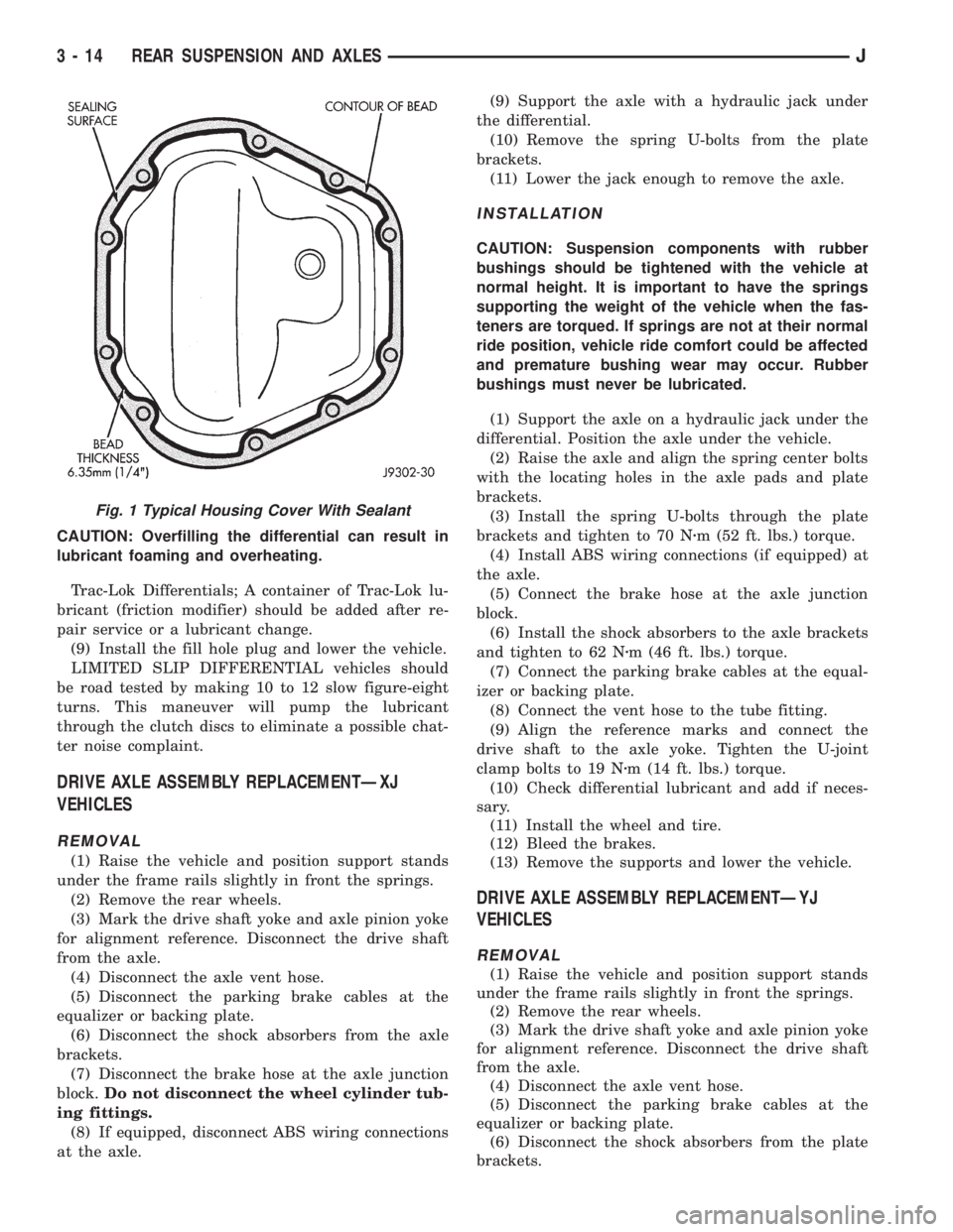
CAUTION: Overfilling the differential can result in
lubricant foaming and overheating.
Trac-Lok Differentials; A container of Trac-Lok lu-
bricant (friction modifier) should be added after re-
pair service or a lubricant change.
(9) Install the fill hole plug and lower the vehicle.
LIMITED SLIP DIFFERENTIAL vehicles should
be road tested by making 10 to 12 slow figure-eight
turns. This maneuver will pump the lubricant
through the clutch discs to eliminate a possible chat-
ter noise complaint.
DRIVE AXLE ASSEMBLY REPLACEMENTÐXJ
VEHICLES
REMOVAL
(1) Raise the vehicle and position support stands
under the frame rails slightly in front the springs.
(2) Remove the rear wheels.
(3) Mark the drive shaft yoke and axle pinion yoke
for alignment reference. Disconnect the drive shaft
from the axle.
(4) Disconnect the axle vent hose.
(5) Disconnect the parking brake cables at the
equalizer or backing plate.
(6) Disconnect the shock absorbers from the axle
brackets.
(7) Disconnect the brake hose at the axle junction
block.Do not disconnect the wheel cylinder tub-
ing fittings.
(8) If equipped, disconnect ABS wiring connections
at the axle.(9) Support the axle with a hydraulic jack under
the differential.
(10) Remove the spring U-bolts from the plate
brackets.
(11) Lower the jack enough to remove the axle.
INSTALLATION
CAUTION: Suspension components with rubber
bushings should be tightened with the vehicle at
normal height. It is important to have the springs
supporting the weight of the vehicle when the fas-
teners are torqued. If springs are not at their normal
ride position, vehicle ride comfort could be affected
and premature bushing wear may occur. Rubber
bushings must never be lubricated.
(1) Support the axle on a hydraulic jack under the
differential. Position the axle under the vehicle.
(2) Raise the axle and align the spring center bolts
with the locating holes in the axle pads and plate
brackets.
(3) Install the spring U-bolts through the plate
brackets and tighten to 70 Nzm (52 ft. lbs.) torque.
(4) Install ABS wiring connections (if equipped) at
the axle.
(5) Connect the brake hose at the axle junction
block.
(6) Install the shock absorbers to the axle brackets
and tighten to 62 Nzm (46 ft. lbs.) torque.
(7) Connect the parking brake cables at the equal-
izer or backing plate.
(8) Connect the vent hose to the tube fitting.
(9) Align the reference marks and connect the
drive shaft to the axle yoke. Tighten the U-joint
clamp bolts to 19 Nzm (14 ft. lbs.) torque.
(10) Check differential lubricant and add if neces-
sary.
(11) Install the wheel and tire.
(12) Bleed the brakes.
(13) Remove the supports and lower the vehicle.
DRIVE AXLE ASSEMBLY REPLACEMENTÐYJ
VEHICLES
REMOVAL
(1) Raise the vehicle and position support stands
under the frame rails slightly in front the springs.
(2) Remove the rear wheels.
(3) Mark the drive shaft yoke and axle pinion yoke
for alignment reference. Disconnect the drive shaft
from the axle.
(4) Disconnect the axle vent hose.
(5) Disconnect the parking brake cables at the
equalizer or backing plate.
(6) Disconnect the shock absorbers from the plate
brackets.
Fig. 1 Typical Housing Cover With Sealant
3 - 14 REAR SUSPENSION AND AXLESJ
Page 114 of 2198
FINAL ASSEMBLY
(1) Install the axle shafts. Refer to Axle Shaft In-
stallation within this group.
(2) Scrape the residual sealant from the housing
and cover mating surfaces. Clean the mating surfaces
with mineral spirits. Apply a bead of MOPARtSili-
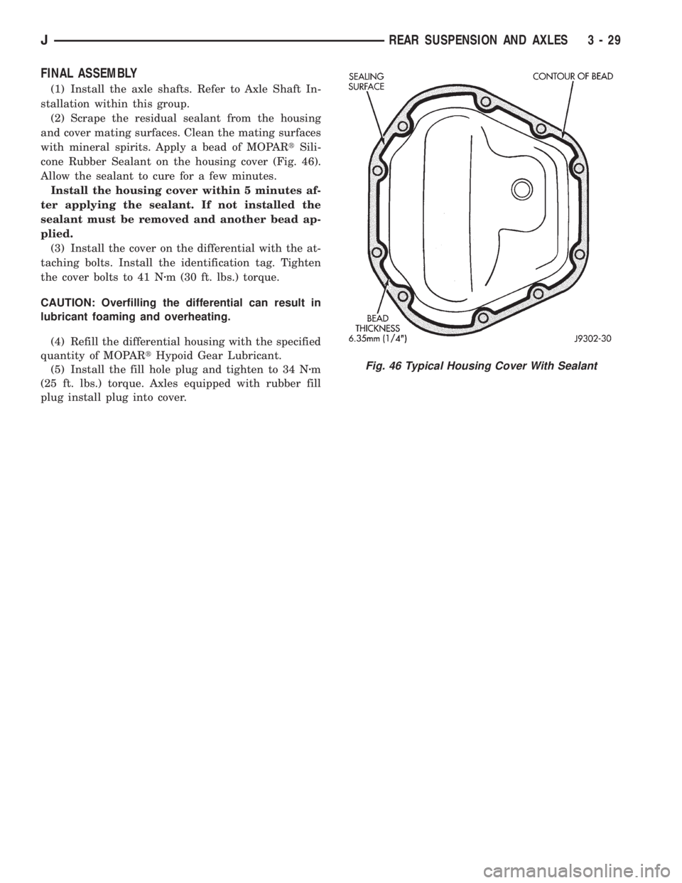
cone Rubber Sealant on the housing cover (Fig. 46).
Allow the sealant to cure for a few minutes.
Install the housing cover within 5 minutes af-
ter applying the sealant. If not installed the
sealant must be removed and another bead ap-
plied.
(3) Install the cover on the differential with the at-
taching bolts. Install the identification tag. Tighten
the cover bolts to 41 Nzm (30 ft. lbs.) torque.
CAUTION: Overfilling the differential can result in
lubricant foaming and overheating.
(4) Refill the differential housing with the specified
quantity of MOPARtHypoid Gear Lubricant.
(5) Install the fill hole plug and tighten to 34 Nzm
(25 ft. lbs.) torque. Axles equipped with rubber fill
plug install plug into cover.
Fig. 46 Typical Housing Cover With Sealant
JREAR SUSPENSION AND AXLES 3 - 29
Page 116 of 2198
LUBRICANT SPECIFICATIONS
Multi-purpose, hypoid gear lubricant should be
used in the 8 1/4 inch axle. The lubricant should
have MIL-L-2105C and API GL 5 quality specifica-
tions. MOPARtHypoid Gear Lubricant conforms to
both of these specifications.
²The factory installed lubricant for the 8 1/4 inch
rear axle is SAE 80W 90 gear lubricant.
²The factory installed lubricant quantity is 6762
fluid oz.
CAUTION: Overfilling the differential can result in
lubricant foaming and overheating.
Refer to Group 0, Lubrication and Maintenance for
additional information.
CAUTION: If axle is submerged in water, lubricant
must be replaced immediately to avoid possible
premature axle failure.
DRIVE AXLE ASSEMBLY REPLACEMENTÐXJ
VEHICLES
REMOVAL
(1) Raise the vehicle. Position support stands un-
der the frame rails slightly in front the springs.
(2) Remove the rear wheels.
(3) Mark the drive shaft yoke and axle pinion yoke
for alignment reference. Disconnect the drive shaft
from the axle.
(4) Disconnect the axle vent hose.
(5) Disconnect the parking brake cables at the
equalizer or backing plate.
(6) Disconnect the shock absorbers from the axle
brackets.
(7) Disconnect the brake hose at the axle junction
block.Do not disconnect the wheel cylinder tub-
ing fittings.
(8) If equipped, disconnect ABS wiring connections
at the axle.
(9) Support the axle with a hydraulic jack under
the differential.
(10) Remove the spring U-bolts from the plate
brackets.
(11) Lower the jack enough to remove the axle.
INSTALLATION
CAUTION: Suspension components with rubber
bushings should be tightened with the vehicle at
normal height. It is important to have the springs
supporting the weight of the vehicle when the fas-
teners are torqued. If springs are not at their normal
ride position, vehicle ride comfort could be affected
and premature bushing wear may occur. Rubber
bushings must never be lubricated.(1) Support the axle on a hydraulic jack under the
differential. Position the axle under the vehicle.
(2) Raise the axle and align the spring center bolts
with the locating holes in the axle pads and plate
brackets.
(3) Install the spring U-bolts through the plate
brackets and tighten to 70 Nzm (52 ft. lbs.) torque.
(4) Install ABS wiring connections (if equipped) at
the axle.
(5) Connect the brake hose at the axle junction
block.
(6) Install the shock absorbers to the axle brackets
and tighten to 62 Nzm (46 ft. lbs.) torque.
(7) Connect the parking brake cables at the equal-
izer or backing plate.
(8) Connect the vent hose to the tube fitting.
(9) Align the reference marks and connect the
drive shaft to the axle yoke. Tighten the U-joint
clamp bolts to 19 Nzm (14 ft. lbs.) torque.
(10) Check differential lubricant and add if neces-
sary.
(11) Install the wheel and tire.
(12) Bleed the brakes.
(13) Remove the supports and lower the vehicle.
LUBRICANT CHANGE
The gear lubricant will drain quicker if the vehicle
has been recently driven.
(1) Raise and support the vehicle.
(2) Remove the lubricant fill hole plug from the dif-
ferential housing cover.
(3) Remove the differential housing cover and
drain the lubricant from the housing.
(4) Clean the housing cavity with a flushing oil,
light engine oil or lint free cloth.Do not use water,
steam, kerosene or gasoline for cleaning.
(5) Remove the sealant from the housing and cover
surfaces. Use solvent to clean the mating surfaces.
(6) Apply a bead of MOPARtSilicone Rubber Seal-
ant to the housing cover (Fig. 2). Allow the sealant to
cure for a few minutes.
Install the housing cover within 5 minutes after
applying the sealant. If not installed the sealant
must be removed and another bead applied.
(7) Install the cover and any identification tag.
Tighten the cover bolts in a criss-cross pattern to 47
Nzm (35 ft. lbs.) torque.
(8) Refill the differential with Mopar Hypoid Gear
Lubricant 13 mm (1/2 in.) below the fill plug hole.
With Trac-Lok differentials, add a container of Mopar
Hypoid Gear Lubricant Additive.
CAUTION: Overfilling the differential can result in
lubricant foaming and overheating.
(9) Install the fill hole plug and lower the vehicle.
JREAR SUSPENSION AND AXLES 3 - 31
Page 143 of 2198
pedal. The proper course of action is to bleed the sys-
tem, or replace thin drums and suspect quality brake
lines and hoses.
HARD PEDAL OR HIGH PEDAL EFFORT
A hard pedal or high pedal effort may be due to lin-
ing that is water soaked, contaminated, glazed, or
badly worn. The power booster or check valve could
also be faulty. Test the booster and valve as described
in this section.
BRAKE DRAG
Brake drag occurs when the lining is in constant
contact with the rotor or drum. Drag can occur at one
wheel, all wheels, fronts only, or rears only. It is a
product of incomplete brakeshoe release. Drag can be
minor or severe enough to overheat the linings, ro-
tors and drums. A drag condition also worsens as
temperature of the brake parts increases.
Brake drag also has a direct effect on fuel economy.
If undetected, minor brake drag can be misdiagnosed
as an engine or transmission/torque converter prob-
lem.
Minor drag will usually cause slight surface char-
ring of the lining. It can also generate hard spots in
rotors and drums from the overheat/cool down pro-
cess. In most cases, the rotors, drums, wheels and
tires are quite warm to the touch after the vehicle is
stopped.
Severe drag can char the brake lining all the way
through. It can also distort and score rotors and
drums to the point of replacement. The wheels, tires
and brake components will be extremely hot. In se-
vere cases, the lining may generate smoke as it chars
from overheating.
An additional cause of drag involves the use of in-
correct length caliper mounting bolts. Bolts that are
too long can cause a partial apply condition. The cor-
rect caliper bolts have a shank length of 67 mm
(2.637 in.), plus or minus 0.6 mm (0.0236 in.). Refer
to the Disc Brake service section for more detail on
caliper bolt dimensions and identification.
Some common causes of brake drag are:
²loose or damaged wheel bearing
²seized or sticking caliper or wheel cylinder piston
²caliper binding on bolts or slide surfaces
²wrong length caliper mounting bolts (too long)
²loose caliper mounting bracket
²distorted rotor, brake drum, or shoes
²brakeshoes binding on worn/damaged support
plates
²severely rusted/corroded components
²misassembled components.
If brake drag occurs at all wheels, the problem may
be related to a blocked master cylinder compensatorport or faulty power booster (binds-does not release).
The condition will worsen as brake temperature in-
creases.
The brakelight switch can also be a cause of drag.
An improperly mounted or adjusted brakelight
switch can prevent full brake pedal return. The re-
sult will be the same as if the master cylinder com-
pensator ports are blocked. The brakes would be
partially applied causing drag.
BRAKE FADE
Brake fade is a product of overheating caused by
brake drag. However, overheating and subsequent
fade can also be caused by riding the brake pedal,
making repeated high deceleration stops in a short
time span, or constant braking on steep roads. Refer
to the Brake Drag information in this section for
causes.
PEDAL PULSATION (NON-ABS BRAKES ONLY)
Pedal pulsation is caused by parts that are loose,
or beyond tolerance limits. This type of pulsation is
constant and will occur every time the brakes are ap-
plied.
Disc brake rotors with excessive lateral runout or
thickness variation, or out of round brake drums are
the primary causes of pulsation.
On vehicles with ABS brakes, remember that pedal
pulsation is normal during antilock mode brake
stops. If pulsation occurs during light to moderate
brake stops, a standard brake part is either loose, or
worn beyond tolerance.
BRAKE PULL
A front pull condition could be the result of:
²contaminated lining in one caliper
²seized caliper piston
²binding caliper
²wrong caliper mounting bolts (too long)
²loose caliper
²loose or corroded mounting bolts
²improper brakeshoes
²damaged rotor
²incorrect wheel bearing adjustment (at one wheel)
A worn, damaged wheel bearing or suspension com-
ponent are further causes of pull. A damaged front
tire (bruised, ply separation) can also cause pull.
Wrong caliper bolts (too long) will cause a partial ap-
ply condition and pull if only one caliper is involved.
A common and frequently misdiagnosed pull condi-
tion is where direction of pull changes after a few
stops. The cause is a combination of brake drag fol-
lowed by fade at the dragging brake unit.
As the dragging brake overheats, efficiency is so re-
duced that fade occurs. If the opposite brake unit is
still functioning normally, its braking effect is magni-
5 - 6 SERVICE BRAKE DIAGNOSISJ
Page 223 of 2198
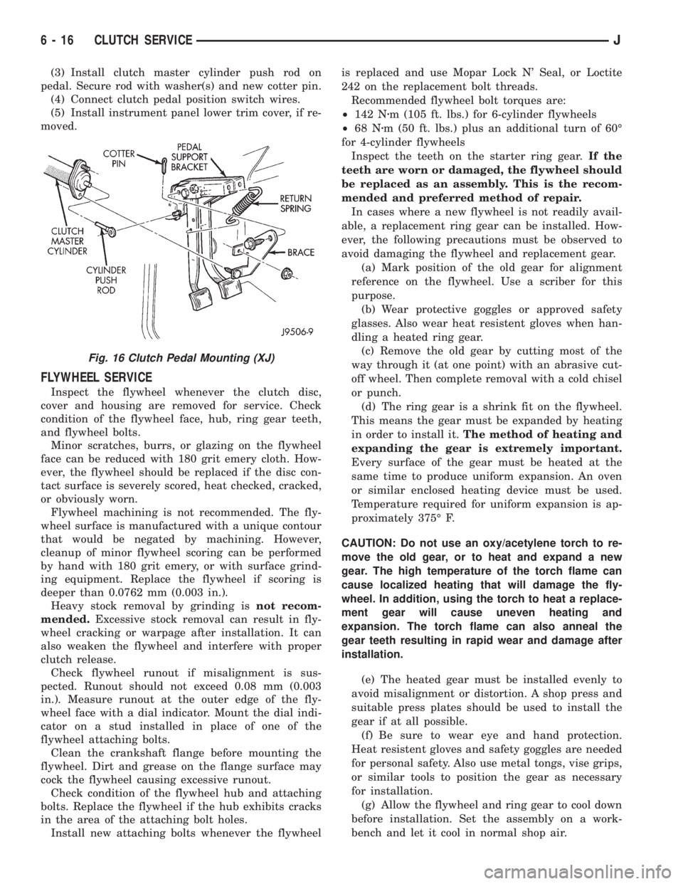
(3) Install clutch master cylinder push rod on
pedal. Secure rod with washer(s) and new cotter pin.
(4) Connect clutch pedal position switch wires.
(5) Install instrument panel lower trim cover, if re-
moved.
FLYWHEEL SERVICE
Inspect the flywheel whenever the clutch disc,
cover and housing are removed for service. Check
condition of the flywheel face, hub, ring gear teeth,
and flywheel bolts.
Minor scratches, burrs, or glazing on the flywheel
face can be reduced with 180 grit emery cloth. How-
ever, the flywheel should be replaced if the disc con-
tact surface is severely scored, heat checked, cracked,
or obviously worn.
Flywheel machining is not recommended. The fly-
wheel surface is manufactured with a unique contour
that would be negated by machining. However,
cleanup of minor flywheel scoring can be performed
by hand with 180 grit emery, or with surface grind-
ing equipment. Replace the flywheel if scoring is
deeper than 0.0762 mm (0.003 in.).
Heavy stock removal by grinding isnot recom-
mended.Excessive stock removal can result in fly-
wheel cracking or warpage after installation. It can
also weaken the flywheel and interfere with proper
clutch release.
Check flywheel runout if misalignment is sus-
pected. Runout should not exceed 0.08 mm (0.003
in.). Measure runout at the outer edge of the fly-
wheel face with a dial indicator. Mount the dial indi-
cator on a stud installed in place of one of the
flywheel attaching bolts.
Clean the crankshaft flange before mounting the
flywheel. Dirt and grease on the flange surface may
cock the flywheel causing excessive runout.
Check condition of the flywheel hub and attaching
bolts. Replace the flywheel if the hub exhibits cracks
in the area of the attaching bolt holes.
Install new attaching bolts whenever the flywheelis replaced and use Mopar Lock N' Seal, or Loctite
242 on the replacement bolt threads.
Recommended flywheel bolt torques are:
²142 Nzm (105 ft. lbs.) for 6-cylinder flywheels
²68 Nzm (50 ft. lbs.) plus an additional turn of 60É
for 4-cylinder flywheels
Inspect the teeth on the starter ring gear.If the
teeth are worn or damaged, the flywheel should
be replaced as an assembly. This is the recom-
mended and preferred method of repair.
In cases where a new flywheel is not readily avail-
able, a replacement ring gear can be installed. How-
ever, the following precautions must be observed to
avoid damaging the flywheel and replacement gear.
(a) Mark position of the old gear for alignment
reference on the flywheel. Use a scriber for this
purpose.
(b) Wear protective goggles or approved safety
glasses. Also wear heat resistent gloves when han-
dling a heated ring gear.
(c) Remove the old gear by cutting most of the
way through it (at one point) with an abrasive cut-
off wheel. Then complete removal with a cold chisel
or punch.
(d) The ring gear is a shrink fit on the flywheel.
This means the gear must be expanded by heating
in order to install it.The method of heating and
expanding the gear is extremely important.
Every surface of the gear must be heated at the
same time to produce uniform expansion. An oven
or similar enclosed heating device must be used.
Temperature required for uniform expansion is ap-
proximately 375É F.
CAUTION: Do not use an oxy/acetylene torch to re-
move the old gear, or to heat and expand a new
gear. The high temperature of the torch flame can
cause localized heating that will damage the fly-
wheel. In addition, using the torch to heat a replace-
ment gear will cause uneven heating and
expansion. The torch flame can also anneal the
gear teeth resulting in rapid wear and damage after
installation.
(e) The heated gear must be installed evenly to
avoid misalignment or distortion. A shop press and
suitable press plates should be used to install the
gear if at all possible.
(f) Be sure to wear eye and hand protection.
Heat resistent gloves and safety goggles are needed
for personal safety. Also use metal tongs, vise grips,
or similar tools to position the gear as necessary
for installation.
(g) Allow the flywheel and ring gear to cool down
before installation. Set the assembly on a work-
bench and let it cool in normal shop air.
Fig. 16 Clutch Pedal Mounting (XJ)
6 - 16 CLUTCH SERVICEJ