Headlamps JEEP CHEROKEE 1995 Service Repair Manual
[x] Cancel search | Manufacturer: JEEP, Model Year: 1995, Model line: CHEROKEE, Model: JEEP CHEROKEE 1995Pages: 2198, PDF Size: 82.83 MB
Page 29 of 2198
CHASSIS AND BODY COMPONENTS
INDEX
page page
Body Components........................ 32
Chassis Component and Wheel Bearing
Lubricants............................. 28
Front Wheel Bearings...................... 28
Headlamps.............................. 33
Manual Steering Gear...................... 30Power Brake System....................... 30
Power Steering System..................... 29
Speedometer Cable....................... 33
Steering Linkage.......................... 28
Tires................................... 32
CHASSIS COMPONENT AND WHEEL BEARING
LUBRICANTS
The chassis component and wheel bearing lubri-
cants that are recommended for Jeep vehicles are
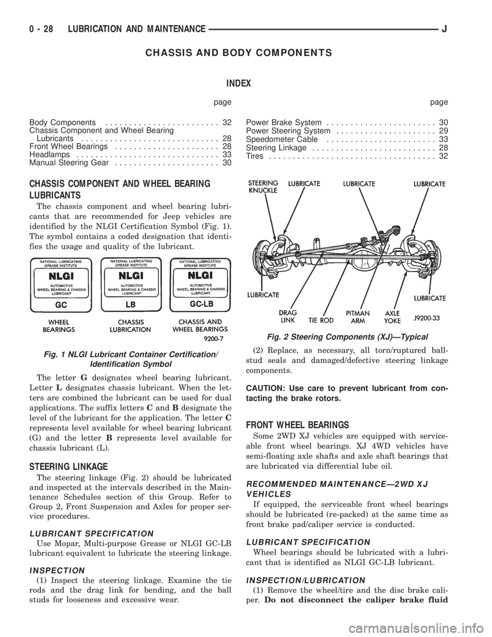
identified by the NLGI Certification Symbol (Fig. 1).
The symbol contains a coded designation that identi-
fies the usage and quality of the lubricant.
The letterGdesignates wheel bearing lubricant.
LetterLdesignates chassis lubricant. When the let-
ters are combined the lubricant can be used for dual
applications. The suffix lettersCandBdesignate the
level of the lubricant for the application. The letterC
represents level available for wheel bearing lubricant
(G) and the letterBrepresents level available for
chassis lubricant (L).
STEERING LINKAGE
The steering linkage (Fig. 2) should be lubricated
and inspected at the intervals described in the Main-
tenance Schedules section of this Group. Refer to
Group 2, Front Suspension and Axles for proper ser-
vice procedures.
LUBRICANT SPECIFICATION
Use Mopar, Multi-purpose Grease or NLGI GC-LB
lubricant equivalent to lubricate the steering linkage.
INSPECTION
(1) Inspect the steering linkage. Examine the tie
rods and the drag link for bending, and the ball
studs for looseness and excessive wear.(2) Replace, as necessary, all torn/ruptured ball-
stud seals and damaged/defective steering linkage
components.
CAUTION: Use care to prevent lubricant from con-
tacting the brake rotors.
FRONT WHEEL BEARINGS
Some 2WD XJ vehicles are equipped with service-
able front wheel bearings. XJ 4WD vehicles have
semi-floating axle shafts and axle shaft bearings that
are lubricated via differential lube oil.
RECOMMENDED MAINTENANCEÐ2WD XJ
VEHICLES
If equipped, the serviceable front wheel bearings
should be lubricated (re-packed) at the same time as
front brake pad/caliper service is conducted.
LUBRICANT SPECIFICATION
Wheel bearings should be lubricated with a lubri-
cant that is identified as NLGI GC-LB lubricant.
INSPECTION/LUBRICATION
(1) Remove the wheel/tire and the disc brake cali-
per.Do not disconnect the caliper brake fluid
Fig. 1 NLGI Lubricant Container Certification/
Identification Symbol
Fig. 2 Steering Components (XJ)ÐTypical
0 - 28 LUBRICATION AND MAINTENANCEJ
Page 34 of 2198
(5) Extra close attention should also be given to
the hood latch components to ensure proper function-
ing.
HEADLAMPS
MAINTENANCE SCHEDULE
Every six months check the headlamp beams to en-
sure that the headlamp beams are correctly posi-
tioned.
AIM ADJUSTMENT
Refer to Group 8L, Lamps for headlamp aim ad-
justment procedures.
SPEEDOMETER CABLE
SERVICE INFORMATION
Speedometer cable lubrication is not necessary. For
service information involving noisy cables, refer to
Group 8E, Instrument Panel and Gauges.
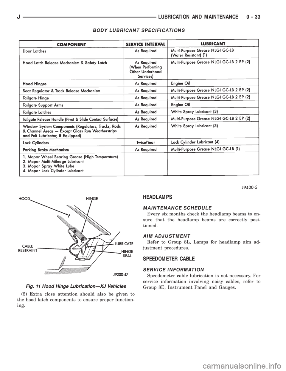
BODY LUBRICANT SPECIFICATIONS
Fig. 11 Hood Hinge LubricationÐXJ Vehicles
JLUBRICATION AND MAINTENANCE 0 - 33
Page 277 of 2198
the specific gravity for temperature variation. Test
the specific gravity of the electrolyte in each battery
cell.
Example: A battery is tested at -12.2ÉC (10ÉF) and
has a specific gravity of 1.240. Determine the actual
specific gravity as follows:
(1) Determine the number of degrees above or be-
low 26.7ÉC (80ÉF):
26.6ÉC - -12.2ÉC = 38.8ÉC (80ÉF - 10ÉF = 70ÉF)
(2) Divide the result from step 1 by 5.5 (10):
38.8ÉC/5.5 = 7 (70ÉF/10 = 7)
(3) Multiply the result from step 2 by the temper-
ature correction factor (0.004):
7 x 0.004 = 0.028
(4) The temperature at testing was below 26.7ÉC
(80ÉF); therefore, the temperature correction is sub-
tracted:
1.240 - 0.028 = 1.212
The corrected specific gravity of the battery in this
example is 1.212.
If the specific gravity of all cells is above 1.235, but
variation between cells is more than 50 points
(0.050), the battery should be replaced.
If the specific gravity of one or more cells is less
than 1.235, charge the battery at a rate of approxi-
mately 5 amperes. Continue charging until 3 consec-
utive specific gravity tests, taken at 1-hour intervals,
are constant. If the cell specific gravity variation is
more than 50 points (0.050) at the end of the charge
period, replace the battery.
When the specific gravity of all cells is above 1.235,
and cell variation is less than 50 points (0.050), the
battery may be load tested.
OPEN CIRCUIT VOLTAGE TEST
A battery open circuit voltage (no load) test will
show state-of-charge of a battery. This test can be
used in place of the hydrometer test if a hydrometer
is not available, or for maintenance-free batteries
with non-removable cell caps.
Before proceeding with this test or load test,
completely charge battery as described in Bat-
tery Charging in this group.
Test battery open circuit voltage as follows:
(1) Before measuring open circuit voltage the sur-
face charge must be removed from the battery. Turn
headlamps on for 15 seconds, then allow up to 5 min-
utes for voltage to stabilize.
(2) Remove both battery cables, negative first.
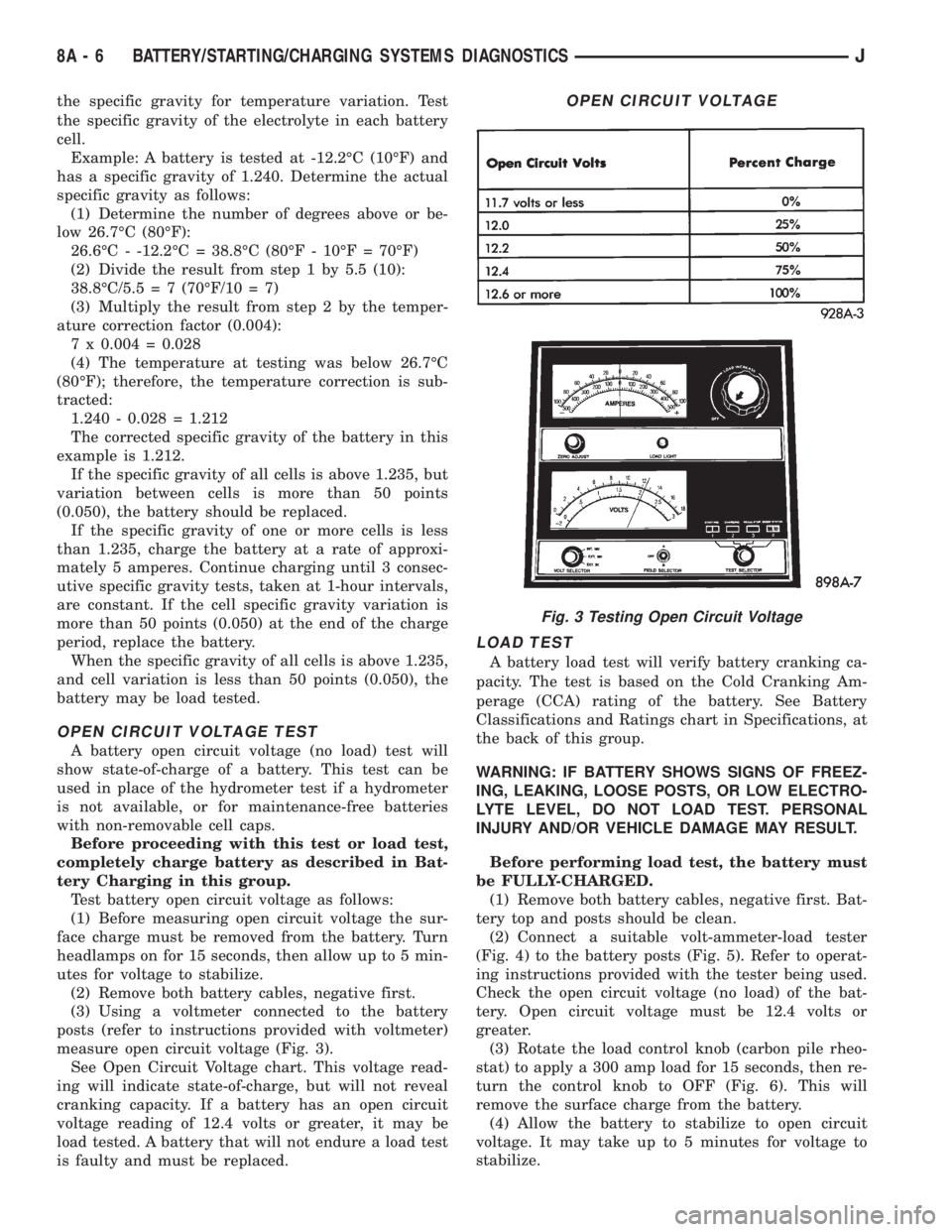
(3) Using a voltmeter connected to the battery
posts (refer to instructions provided with voltmeter)
measure open circuit voltage (Fig. 3).
See Open Circuit Voltage chart. This voltage read-
ing will indicate state-of-charge, but will not reveal
cranking capacity. If a battery has an open circuit
voltage reading of 12.4 volts or greater, it may be
load tested. A battery that will not endure a load test
is faulty and must be replaced.
LOAD TEST
A battery load test will verify battery cranking ca-
pacity. The test is based on the Cold Cranking Am-
perage (CCA) rating of the battery. See Battery
Classifications and Ratings chart in Specifications, at
the back of this group.
WARNING: IF BATTERY SHOWS SIGNS OF FREEZ-
ING, LEAKING, LOOSE POSTS, OR LOW ELECTRO-
LYTE LEVEL, DO NOT LOAD TEST. PERSONAL
INJURY AND/OR VEHICLE DAMAGE MAY RESULT.
Before performing load test, the battery must
be FULLY-CHARGED.
(1) Remove both battery cables, negative first. Bat-
tery top and posts should be clean.
(2) Connect a suitable volt-ammeter-load tester
(Fig. 4) to the battery posts (Fig. 5). Refer to operat-
ing instructions provided with the tester being used.
Check the open circuit voltage (no load) of the bat-
tery. Open circuit voltage must be 12.4 volts or
greater.
(3) Rotate the load control knob (carbon pile rheo-
stat) to apply a 300 amp load for 15 seconds, then re-
turn the control knob to OFF (Fig. 6). This will
remove the surface charge from the battery.
(4) Allow the battery to stabilize to open circuit
voltage. It may take up to 5 minutes for voltage to
stabilize.
OPEN CIRCUIT VOLTAGE
Fig. 3 Testing Open Circuit Voltage
8A - 6 BATTERY/STARTING/CHARGING SYSTEMS DIAGNOSTICSJ
Page 347 of 2198
HEADLAMP HIGH BEAM INDICATOR LAMP
The high beam indicator lamp is controlled by the
headlamp dimmer (multi-function) switch. One side
of the indicator bulb is grounded at all times. The
other side of the bulb receives battery feed through
the contacts of the dimmer switch when the multi-
function switch stalk is actuated to turn the head-
lamp high beams on. Refer to Group 8L - Lamps for
more information.
LOW FUEL WARNING LAMP
A Light-Emitting Diode (LED) on the face of the
fuel gauge will light when the fuel level falls below
approximately 4 gallons. A low fuel warning module
attached to the rear of the fuel gauge controls when
the LED will light. When the module senses 66.5
ohms or more resistance from the fuel level sending
unit for 10 continuous seconds, the LED will light.
When the module senses 63.5 ohms or less resistance
from the fuel level sending unit for 20 continuous
seconds, the LED is turned off.
LOW OIL PRESSURE WARNING LAMP
The low oil pressure warning lamp lights with the
ignition switch in the ON position and the engine not
running. The lamp should be off when the engine is
running. Battery voltage is supplied to one side of
the indicator bulb when the ignition switch is turned
ON. The warning lamp side of the combination oil
pressure sending unit is connected to the other side
of the bulb. When normal engine oil pressure is ap-
plied to the sending unit, resistance on the warning
lamp side is high and the lamp goes off. When engine
oil pressure is too low, resistance on the warning
lamp side of the sending unit is low, which causes
the bulb to light.
LOW WASHER FLUID WARNING LAMP
The low washer fluid warning lamp indicates when
the fluid level in the washer reservoir is too low. The
washer fluid level sensor uses a float in the reservoir
to monitor fluid level. The action of the float opens or
closes the switch within the sensor that provides ig-
nition-switched battery voltage to the lamp bulb. Re-
fer to Group 8K - Wiper and Washer Systems for
more information.
MALFUNCTION INDICATOR LAMP
The CHECK ENGINE or Malfunction Indicator
Lamp (MIL) lights each time the ignition switch is
turned ON, and stays on for 3 seconds as a bulb test.
If the Powertrain Control Module (PCM) receives an
incorrect signal or no signal from certain fuel oremission system related circuits or components, the
lamp is turned on. This will indicate that the PCM
has recorded a Diagnostic Trouble Code (DTC) in
electronic memory for a circuit or component mal-
function. Refer to Group 14 - Fuel System for more
information.
SEAT BELT REMINDER LAMP
The seat belt reminder lamp lights for 4 to 8 sec-
onds after the ignition switch is turned to the ON po-
sition. A timer in the chime/buzzer module controls
ignition-switched battery feed to the lamp. Refer to
Group 8U - Chime/Buzzer Warning Systems for more
information.
TURN SIGNAL INDICATOR LAMPS
The left and right turn signal indicator lamps are
controlled by the turn signal and hazard warning
(multi-function) switches. One side of the bulb for
each lamp is grounded at all times. The other side of
the bulb receives battery feed through the contacts of
the multi-function switch when the turn signal lever
(multi-function switch stalk) or hazard warning but-
ton are actuated. Refer to Group 8J - Turn Signal
and Hazard Warning Systems for more information.
UPSHIFT INDICATOR LAMP
Vehicles equipped with manual transmissions have
an optional upshift indicator lamp. Ground feed for
the lamp is switched by the Powertrain Control Mod-
ule (PCM). The lamp lights to indicate when the
driver should shift to the next highest gear for best
fuel economy. The PCM will turn the lamp off after 3
to 5 seconds if the upshift is not performed. The lamp
will remain off until the vehicle stops accelerating
and is brought back to the range of lamp operation,
or until the transmission is shifted into another gear.
The indicator lamp is normally on when the igni-
tion switch is turned ON and is turned off when the
engine is started. The lamp will be turned on during
vehicle operation according to engine speed and load.
CLUSTER ILLUMINATION LAMPS
All cluster illumination lamps receive battery feed
from the instrument lamps fuse in the fuseblock
module through the panel dimmer rheostat of the
headlamp switch. When the park or headlamps are
on, the cluster illumination lamps light. Illumination
brightness can be adjusted by rotating the headlamp
switch knob (clockwise to dim, counterclockwise to
brighten).
8E - 4 INSTRUMENT PANEL AND GAUGESÐXJJ
Page 357 of 2198
(2) Disconnect battery negative cable. Remove in-
strument cluster bezel and cluster assembly. Unplug
cluster connector A. Connect battery negative cable.
Turn headlamps on and select high beam. Check for
battery voltage at cavity A4 of cluster connector A. If
OK, replace indicator bulb. If not OK, repair circuit
to headlamp dimmer (multi-function) switch as re-
quired.
LOW FUEL WARNING LAMP
(1) Check that fuel gauge is operating as designed.
See Fuel Gauge Calibration chart in Specifications. If
OK, go to next step. If not OK, see Fuel Gauge in
this section for diagnosis.
(2) With at least 10 gallons of fuel in fuel tank, un-
plug fuel tank sending unit connector. Turn ignition
switch to ON and wait 10 seconds. Lamp (LED)
should light. Reconnect fuel tank sending unit and
wait 20 seconds. Lamp (LED) should go off. If not
OK, replace low fuel warning lamp module.
LOW OIL PRESSURE WARNING LAMP
The diagnosis found here addresses an inoperative
lamp condition. If the problem being diagnosed is re-
lated to lamp accuracy, be certain to confirm that
problem is with lamp and not with engine oiling sys-
tem. Actual engine oil pressure should be checked
with a test gauge before you proceed with lamp diag-
nosis. Refer to Group 9 - Engines for more informa-
tion.
(1) Turn ignition switch to ON. Lamp should light.
Start engine. Lamp should go off. If not OK, turn en-
gine off and go to next step.
(2) Unplug connector at oil pressure switch (Fig.
3). The switch is located on right side of engine block.
On 2.5L engine, it is just forward of ignition distrib-
utor and just to the rear of generator mounting
bracket. On 4.0L engine, it is just to the rear of igni-
tion distributor and above oil filter adapter. Install a
jumper wire from connector to a good ground. Turn
ignition switch to ON. Lamp should light. Unplug
jumper wire. Lamp should go out. If OK, replace oil
pressure switch. If not OK, go to next step.
(3) Turn ignition switch to OFF. Disconnect battery
negative cable. Remove instrument cluster bezel and
cluster assembly. Install a jumper wire from cavity
B7 (cavity B8 - RHD) of cluster connector A to a good
ground. Connect battery negative cable and turn ig-
nition switch to ON. Lamp should light. If OK, go to
next step. If not OK, replace lamp bulb.
(4) Turn ignition switch to OFF. Disconnect battery
negative cable. Unplug instrument cluster connector
A. Check continuity between cavity B7 (cavity B8 -
RHD) of cluster connector A and a good ground.
There should be no continuity. If OK, go to next step.
If not OK, repair short circuit as required.
(5) Check continuity between cavity B7 (cavity B8
- RHD) of cluster connector A and oil pressure switchconnector. There should be continuity. If not OK, re-
pair open circuit as required.
LOW WASHER FLUID WARNING LAMP
(1) Unplug washer fluid level switch connector.
Turn ignition switch to ON. Check for battery voltage
at connector cavity A. If OK, turn ignition switch to
OFF and go to next step. If not OK, repair open cir-
cuit to fuse F6 in PDC.
(2) Install a jumper wire from cavity A to cavity B
of washer fluid level switch connector. Turn ignition
switch to ON. Lamp should light. Unplug jumper and
lamp should go OFF. If OK, replace washer fluid
level switch. If not OK, go to next step.
(3) Turn ignition switch to OFF. Disconnect battery
negative cable. Remove instrument cluster bezel and
cluster assembly. Unplug instrument cluster (tell-
tale) connector B. Check continuity between cavity 16
(cavity 1 - RHD) of cluster connector B and a good
ground. There should be continuity. If OK, plug clus-
ter connector B back into cluster and go to next step.
If not OK, repair open circuit to ground as required.
(4) Connect battery negative cable. Install a
jumper wire from a 12-volt battery feed to cavity 1
(cavity 16 - RHD) of cluster connector B. Lamp
should light. If OK, go to next step. If not OK, re-
place bulb.
(5) Disconnect battery negative cable. Unplug clus-
ter connector B. Check continuity between cavity 1
(cavity 16 - RHD) of cluster connector B and a good
ground. There should be no continuity. If OK, go to
next step. If not OK, repair short circuit to switch as
required.
(6) Check continuity between cavity 1 (cavity 16 -
RHD) of cluster connector B and cavity B of washer
fluid level switch connector. There should be continu-
ity. If not OK, repair open circuit to switch as re-
quired.
MALFUNCTION INDICATOR LAMP
The diagnosis found here addresses an inoperative
lamp condition. If the lamp comes on and stays on
with engine running, refer to Group 14 - Fuel System
for diagnosis. If no fuel or emission system problem
is found, the following procedure will help locate a
short or open in the lamp circuit.
(1) Disconnect battery negative cable. Unplug PCM
connector. Install a jumper wire from cavity 32 of
PCM connector (Fig. 5) to a good ground. Connect
battery negative cable. Turn ignition switch to ON.
Lamp should light. Remove jumper wire and lamp
should go OFF. If OK, refer to Powertrain Diagnostic
Procedures to check PCM. If not OK, go to next step.
(2) Turn ignition switch to OFF. Disconnect battery
negative cable. Remove instrument cluster bezel and
cluster assembly. Install a jumper wire from cavity 2
(cavity 15 - RHD) of cluster (tell-tale) connector B to
a good ground. Connect battery negative cable. Turn
8E - 14 INSTRUMENT PANEL AND GAUGESÐXJJ
Page 369 of 2198
voltage is supplied to one side of the indicator bulb. A
ground path for the bulb is provided by 3 switches.
The bulb will light when:
²the brake warning switch is closed (indicating un-
equal brake system hydraulic pressures possibly due
to brake fluid leakage)
²the ignition switch is in the START position (bulb
test)
²the parking brake switch is closed (parking brake
is applied).
Refer to Group 5 - Brakes for more information.
FOUR-WHEEL DRIVE INDICATOR LAMP
This lamp lights when the transfer case is engaged
in the 4H or 4L position. Voltage is supplied to one
side of the indicator bulb. A switch on the front axle
disconnect housing is connected to the other side of
the indicator bulb. When the switch is closed, a path
to ground is provided and the indicator bulb lights.
HEADLAMP HIGH BEAM INDICATOR LAMP
The high beam indicator lamp is controlled by the
headlamp dimmer switch. One side of the indicator
bulb is grounded at all times. The other side of the
bulb receives battery feed through the contacts of the
dimmer switch when the turn signal switch lever is
actuated to turn the headlamp high beams on. Refer
to Group 8L - Lamps for more information.
MALFUNCTION INDICATOR LAMP
The CHECK ENGINE or Malfunction Indicator
Lamp (MIL) lights each time the ignition switch is
turned ON, and stays on for 3 seconds as a bulb test.
If the Powertrain Control Module (PCM) receives an
incorrect signal or no signal from certain fuel or
emission system related circuits or components, the
lamp is turned on. This will indicate that the PCM
has recorded a Diagnostic Trouble Code (DTC) in
electronic memory for a circuit or component mal-
function. Refer to Group 14 - Fuel System for more
information.
SEAT BELT REMINDER LAMP
The seat belt reminder lamp lights for 4 to 8 sec-
onds after the ignition switch is turned to the ON po-sition. A timer in the chime/buzzer module controls
ignition-switched battery feed to the lamp. Refer to
Group 8U - Chime/Buzzer Warning Systems for more
information.
TURN SIGNAL INDICATOR LAMPS
The left and right turn signal indicator lamps are
controlled by the turn signal and hazard warning
switches. One side of the bulb for each lamp is
grounded at all times. The other side of the bulb re-
ceives battery feed through the contacts of the turn
signal switch, when the turn signal lever or hazard
warning button are actuated. Refer to Group 8J -
Turn Signal and Hazard Warning Systems for more
information.
UPSHIFT INDICATOR LAMP
Vehicles equipped with manual transmissions have
an optional upshift indicator lamp. Ground feed for
the lamp is switched by the Powertrain Control Mod-
ule (PCM). The lamp lights to indicate when the
driver should shift to the next highest gear for best
fuel economy. The PCM will turn the lamp off after 3
to 5 seconds if the upshift is not performed. The lamp
will remain off until the vehicle stops accelerating
and is brought back to the range of lamp operation,
or until the transmission is shifted into another gear.
The indicator lamp is normally on when the igni-
tion switch is turned ON and is turned off when the
engine is started. The lamp will be turned on during
vehicle operation according to engine speed and load.
CLUSTER ILLUMINATION LAMPS
All cluster illumination lamps receive battery feed
from the instrument lamps fuse in the fuseblock
module through the panel dimmer switch. When the
park or headlamps are on, the cluster illumination
lamps light. Illumination brightness can be adjusted
by rotating the panel dimmer thumb-wheel, which is
next to the headlamp switch.
8E - 26 INSTRUMENT PANEL AND GAUGESÐYJJ
Page 376 of 2198
(9) Turn ignition switch to START position and
hold there. Check for continuity between terminal for
circuit G11 of ignition switch and a good ground.
There should be continuity. If not OK, replace igni-
tion switch.
(10) Unplug brake warning switch connector.
Check for continuity between parking brake switch
connector and a good ground. There should be no
continuity. If OK, go to next step. If not OK, repair
short circuit as required.
(11) Check for continuity between parking brake
switch connector and brake warning switch connector
cavity for circuit G11. There should be continuity. If
OK, replace parking brake switch. If not OK, repair
open circuit to brake warning switch as required.
FOUR-WHEEL DRIVE INDICATOR LAMP
(1) Apply parking brake, start engine, vehicle in
4WD Lock or 4WD.
(2) Unplug switch and touch harness side of wire
to ground. Lamp should light. If OK, check switch
operation, replace if bad. If bulb is OK, repair open
to indicator.
HEADLAMP HIGH BEAM INDICATOR LAMP
(1) Check that headlamp high beams are func-
tional. If OK, go to next step. If not OK, refer to
Group 8L - Lamps for diagnosis of headlamp system.
(2) Disconnect battery negative cable. Remove left
instrument cluster bezel and main cluster assembly.
Unplug cluster connector. Connect battery negative
cable. Turn headlamps on and select high beam.
Check for battery voltage at cavity 17 of cluster con-
nector. If OK, replace indicator bulb. If not OK, re-
pair circuit to headlamp dimmer switch as required.
MALFUNCTION INDICATOR LAMP
The diagnosis found here addresses an inoperative
lamp condition. If the lamp comes on and stays on
with engine running, refer to Group 14 - Fuel System
for diagnosis. If no fuel or emission system problem
is found, the following procedure will help locate a
short or open in the lamp circuit.
(1) Disconnect battery negative cable. Unplug PCM
connector. Install a jumper wire from cavity 32 of
PCM connector (Fig. 5) to a good ground. Connect
battery negative cable. Turn ignition switch to ON.
Lamp should light. Remove jumper wire and lamp
should go OFF. If OK, refer to Powertrain Diagnostic
Procedures to check PCM. If not OK, go to next step.
(2) Turn ignition switch to OFF. Disconnect battery
negative cable. Remove left instrument cluster bezel
and main cluster assembly. Install a jumper wire
from cavity 2 of cluster connector to a good ground.
Connect battery negative cable. Turn ignition switch
to ON. Lamp should light. If OK, go to next step. If
not OK, replace bulb.(3) Turn ignition switch to OFF. Disconnect battery
negative cable. Unplug cluster connector. Check for
continuity between cavity 2 of cluster connector and
a good ground. There should be no continuity. If OK,
go to next step. If not OK, repair short circuit to
PCM as required.
(4) Check continuity between cavity 2 of cluster
connector and cavity 32 of PCM connector. There
should be continuity. If not OK, repair open circuit to
PCM as required.
SEAT BELT REMINDER LAMP
(1) Refer to Group 8U - Chime/Buzzer Warning
Systems to check chime/buzzer module operation. If
OK, go to next step. If not OK, replace chime/buzzer
module.
(2) Disconnect battery negative cable. Remove left
instrument cluster bezel and main cluster assembly.
Unplug cluster connector. Check for continuity be-
tween cavity 20 of cluster connector and a good
ground. There should be continuity. If OK, plug clus-
ter connector back into cluster and go to next step. If
not OK, repair open circuit to ground as required.
(3) Connect battery negative cable. Install a
jumper wire between a 12-volt battery feed and cav-
ity 16 of cluster connector. Lamp should light. If OK,
go to next step. If not OK, replace bulb.
(4) Disconnect battery negative cable. Unplug
chime/buzzer module from fuseblock module. Unplug
cluster connector. Check for continuity between cav-
ity 16 of cluster connector and a good ground. There
should be no continuity. If OK, go to next step. If not
OK, repair short circuit to chime/buzzer module as
required.
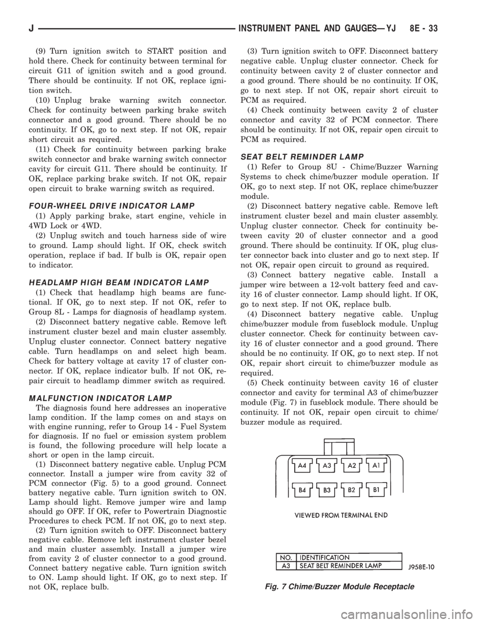
(5) Check continuity between cavity 16 of cluster
connector and cavity for terminal A3 of chime/buzzer
module (Fig. 7) in fuseblock module. There should be
continuity. If not OK, repair open circuit to chime/
buzzer module as required.
Fig. 7 Chime/Buzzer Module Receptacle
JINSTRUMENT PANEL AND GAUGESÐYJ 8E - 33
Page 453 of 2198
SERVICE PROCEDURES
INDEX
page page
Back-Up/Rear Turn Signal/Tail Lamp Bulb
ReplacementÐXJ....................... 12
Center High Mounted Stop Lamp (CHMSL)ÐXJ . . 12
Daytime Running Lights (Canada Only)ÐXJ..... 15
Drl Module ReplacementÐXJ................ 15
Fog Lamp ReplacementÐXJ.................. 9
Fog Lamp Switch ReplacementÐXJ........... 10
Fog LampsÐXJ........................... 7
Front Park/Turn Signal Lamp Bulb
ReplacementÐXJ........................ 9
Headlamp Alignment PreparationÐXJ........... 6
Headlamp AlignmentÐXJ.................... 6
Headlamp Bulb ReplacementÐXJ.............. 7Headlamp Delay Function Trouble DiagnosisÐXJ . 14
Headlamp Delay Module ReplacementÐXJ...... 14
Headlamp SwitchÐXJ...................... 10
Headlamp/Fog Lamp Adjustment Using Alignment
ScreenÐXJ............................. 7
License Plate LampÐXJ.................... 12
Multi-Function Switch Service ProceduresÐXJ.... 11
Sentinel Headlamp Delay ModuleÐXJ.......... 14
Side Marker Lamp Bulb ReplacementÐXJ....... 10
Underhood Lamp Bulb ReplacementÐXJ....... 13
Underhood Lamp ReplacementÐXJ........... 13
Underhood Lamp Service InformationÐXJ....... 12
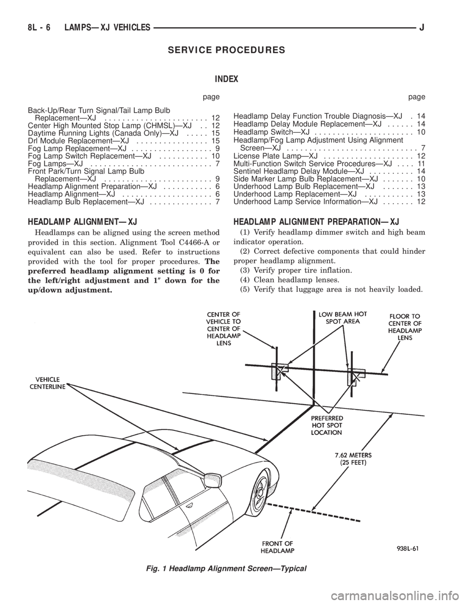
HEADLAMP ALIGNMENTÐXJ
Headlamps can be aligned using the screen method
provided in this section. Alignment Tool C4466-A or
equivalent can also be used. Refer to instructions
provided with the tool for proper procedures.The
preferred headlamp alignment setting is 0 for
the left/right adjustment and 1(down for the
up/down adjustment.
HEADLAMP ALIGNMENT PREPARATIONÐXJ
(1) Verify headlamp dimmer switch and high beam
indicator operation.
(2) Correct defective components that could hinder
proper headlamp alignment.
(3) Verify proper tire inflation.
(4) Clean headlamp lenses.
(5) Verify that luggage area is not heavily loaded.
Fig. 1 Headlamp Alignment ScreenÐTypical
8L - 6 LAMPSÐXJ VEHICLESJ
Page 454 of 2198
(6) Fuel tank should be FULL. Add 2.94 kg (6.5
lbs.) of weight over the fuel tank for each estimated
gallon of missing fuel.
HEADLAMP/FOG LAMP ADJUSTMENT USING
ALIGNMENT SCREENÐXJ
ALIGNMENT SCREEN PREPARATION
(1) Position vehicle on a level surface perpendicu-
lar to a flat wall 7.62 meters (25 ft) away from front
of headlamp lens (Fig. 1).
(2) If necessary, tape a line on the floor 7.62
meters (25 ft) away from and parallel to the wall.
(3) Measure from the floor up 1.27 meters (5 ft)
and tape a line on the wall at the centerline of the
vehicle. Sight along the centerline of the vehicle
(from rear of vehicle forward) to verify accuracy of
the line placement.
(4) Rock vehicle side-to-side three times to allow
suspension to stabilize.
(5) Jounce front suspension three times by pushing
downward on front bumper and releasing.
(6) Measure the distance from the center of head-
lamp lens to the floor. Transfer measurement to the
alignment screen (with tape). Use this line for up/
down adjustment reference.
(7) Measure distance from the centerline of the ve-
hicle to the center of each headlamp being aligned.
Transfer measurements to screen (with tape) to each
side of vehicle centerline. Use these lines for left/
right adjustment reference.
ADJUSTMENT
(1) Remove screws and both headlamp bezels.
(2) Clean front of the headlamps.
(3) Place headlamps on LOW beam.
(4) Cover front of the headlamp that is not being
adjusted.
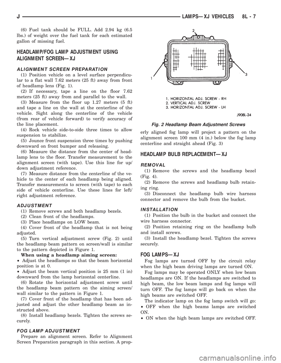
(5) Turn vertical adjustment screw (Fig. 2) until
the headlamp beam pattern on screen/wall is similar
to the pattern depicted in Figure 1.
When using a headlamp aiming screen:
²Adjust the headlamps so that the beam horizontal
position is at 0.
²Adjust the beam vertical position is 25 mm (1 in)
downward from the lamp horizontal centerline.
(6) Rotate the horizontal adjustment screw until
the headlamp beam pattern on the aiming screen/
wall similar to the pattern in Figure 1.
(7) Cover front of the headlamp that has been ad-
justed and adjust the other headlamp beam as in-
structed above.
(8) Install headlamp bezels. Tighten the screws se-
curely.
FOG LAMP ADJUSTMENT
Prepare an alignment screen. Refer to Alignment
Screen Preparation paragraph in this section. A prop-erly aligned fog lamp will project a pattern on the
alignment screen 100 mm (4 in.) below the fog lamp
centerline and straight ahead (Fig. 3)
HEADLAMP BULB REPLACEMENTÐXJ
REMOVAL
(1) Remove the screws and the headlamp bezel
(Fig. 4).
(2) Remove the screws and headlamp bulb retain-
ing ring.
(3) Disconnect the headlamp bulb wire harness
connector and remove the bulb from the bucket.
INSTALLATION
(1) Position the bulb in the bucket and connect the
wire harness connector.
(2) Position retaining ring on the headlamp bulb
and install screws.
(3) Install the headlamp bezel. Tighten the screws
securely.
FOG LAMPSÐXJ
Fog lamps are turned OFF by the circuit relay
when the high beam driving lamps are turned ON.
Fog lamps may be operated ONLY when low beam
headlamps are ON. If the headlamps are switched to
high beam, the low beam lamps and fog lamps will
turn OFF. The fog lamps will go back on when the
high beams are switched OFF.
The indicator lamp on the fog lamp switch will go:
²OFF when the high beams lamps are switched
ON.
²ON when the high beam lamps are switched OFF.
Fig. 2 Headlamp Beam Adjustment Screws
JLAMPSÐXJ VEHICLES 8L - 7
Page 461 of 2198
INSTALLATION
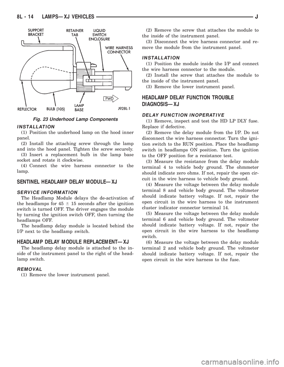
(1) Position the underhood lamp on the hood inner
panel.
(2) Install the attaching screw through the lamp
and into the hood panel. Tighten the screw securely.
(3) Insert a replacement bulb in the lamp base
socket and rotate it clockwise.
(4) Connect the wire harness connector to the
lamp.
SENTINEL HEADLAMP DELAY MODULEÐXJ
SERVICE INFORMATION
The Headlamp Module delays the de-activation of
the headlamps for 45615 seconds after the ignition
switch is turned OFF. The driver engages the module
by turning the ignition switch OFF, then turning the
headlamps OFF.
The headlamp delay module is located behind the
I/P next to the headlamp switch.
HEADLAMP DELAY MODULE REPLACEMENTÐXJ
The headlamp delay module is attached to the in-
side of the instrument panel to the right of the head-
lamp switch.
REMOVAL
(1) Remove the lower instrument panel.(2) Remove the screw that attaches the module to
the inside of the instrument panel.
(3) Disconnect the wire harness connector and re-
move the module from the instrument panel.
INSTALLATION
(1) Position the module inside the I/P and connect
the wire harness connector to the module.
(2) Install the screw that attaches the module to
the inside of the instrument panel.
(3) Remove the lower instrument panel.
HEADLAMP DELAY FUNCTION TROUBLE
DIAGNOSISÐXJ
DELAY FUNCTION INOPERATIVE
(1) Remove, inspect and test the HD LP DLY fuse.
Replace if defective.
(2) Remove the delay module from the I/P. Do not
disconnect the wire harness connector. Turn the igni-
tion switch to the RUN position. Place the headlamp
switch in headlamps ON position. Turn the ignition
to the OFF position for a resistance test.
(3) Measure the resistance from the delay module
terminal 4 to vehicle body ground. The ohmmeter
should indicate zero ohms. If not, repair the open cir-
cuit in the wire harness to vehicle body ground.
(4) Measure the voltage between the delay module
terminal 8 and vehicle body ground. The voltmeter
should indicate battery voltage. If not, repair the
open circuit in the wire harness to the instrument
cluster indicator connector terminal 14.
(5) Measure the voltage between the delay module
terminal 6 and vehicle body ground. The voltmeter
should indicate battery voltage. If not, repair the
open circuit in the wire harness to the headlamp
switch.
(6) Measure the voltage between the delay module
terminal 2 and vehicle body ground. The voltmeter
should indicate battery voltage. If not, repair the
open circuit in the wire harness to the fuse.Fig. 23 Underhood Lamp Components
8L - 14 LAMPSÐXJ VEHICLESJ