dimensions JEEP CHEROKEE 1995 Service Repair Manual
[x] Cancel search | Manufacturer: JEEP, Model Year: 1995, Model line: CHEROKEE, Model: JEEP CHEROKEE 1995Pages: 2198, PDF Size: 82.83 MB
Page 143 of 2198
pedal. The proper course of action is to bleed the sys-
tem, or replace thin drums and suspect quality brake
lines and hoses.
HARD PEDAL OR HIGH PEDAL EFFORT
A hard pedal or high pedal effort may be due to lin-
ing that is water soaked, contaminated, glazed, or
badly worn. The power booster or check valve could
also be faulty. Test the booster and valve as described
in this section.
BRAKE DRAG
Brake drag occurs when the lining is in constant
contact with the rotor or drum. Drag can occur at one
wheel, all wheels, fronts only, or rears only. It is a
product of incomplete brakeshoe release. Drag can be
minor or severe enough to overheat the linings, ro-
tors and drums. A drag condition also worsens as
temperature of the brake parts increases.
Brake drag also has a direct effect on fuel economy.
If undetected, minor brake drag can be misdiagnosed
as an engine or transmission/torque converter prob-
lem.
Minor drag will usually cause slight surface char-
ring of the lining. It can also generate hard spots in
rotors and drums from the overheat/cool down pro-
cess. In most cases, the rotors, drums, wheels and
tires are quite warm to the touch after the vehicle is
stopped.
Severe drag can char the brake lining all the way
through. It can also distort and score rotors and
drums to the point of replacement. The wheels, tires
and brake components will be extremely hot. In se-
vere cases, the lining may generate smoke as it chars
from overheating.
An additional cause of drag involves the use of in-
correct length caliper mounting bolts. Bolts that are
too long can cause a partial apply condition. The cor-
rect caliper bolts have a shank length of 67 mm
(2.637 in.), plus or minus 0.6 mm (0.0236 in.). Refer
to the Disc Brake service section for more detail on
caliper bolt dimensions and identification.
Some common causes of brake drag are:
²loose or damaged wheel bearing
²seized or sticking caliper or wheel cylinder piston
²caliper binding on bolts or slide surfaces
²wrong length caliper mounting bolts (too long)
²loose caliper mounting bracket
²distorted rotor, brake drum, or shoes
²brakeshoes binding on worn/damaged support
plates
²severely rusted/corroded components
²misassembled components.
If brake drag occurs at all wheels, the problem may
be related to a blocked master cylinder compensatorport or faulty power booster (binds-does not release).
The condition will worsen as brake temperature in-
creases.
The brakelight switch can also be a cause of drag.
An improperly mounted or adjusted brakelight
switch can prevent full brake pedal return. The re-
sult will be the same as if the master cylinder com-
pensator ports are blocked. The brakes would be
partially applied causing drag.
BRAKE FADE
Brake fade is a product of overheating caused by
brake drag. However, overheating and subsequent
fade can also be caused by riding the brake pedal,
making repeated high deceleration stops in a short
time span, or constant braking on steep roads. Refer
to the Brake Drag information in this section for
causes.
PEDAL PULSATION (NON-ABS BRAKES ONLY)
Pedal pulsation is caused by parts that are loose,
or beyond tolerance limits. This type of pulsation is
constant and will occur every time the brakes are ap-
plied.
Disc brake rotors with excessive lateral runout or
thickness variation, or out of round brake drums are
the primary causes of pulsation.
On vehicles with ABS brakes, remember that pedal
pulsation is normal during antilock mode brake
stops. If pulsation occurs during light to moderate
brake stops, a standard brake part is either loose, or
worn beyond tolerance.
BRAKE PULL
A front pull condition could be the result of:
²contaminated lining in one caliper
²seized caliper piston
²binding caliper
²wrong caliper mounting bolts (too long)
²loose caliper
²loose or corroded mounting bolts
²improper brakeshoes
²damaged rotor
²incorrect wheel bearing adjustment (at one wheel)
A worn, damaged wheel bearing or suspension com-
ponent are further causes of pull. A damaged front
tire (bruised, ply separation) can also cause pull.
Wrong caliper bolts (too long) will cause a partial ap-
ply condition and pull if only one caliper is involved.
A common and frequently misdiagnosed pull condi-
tion is where direction of pull changes after a few
stops. The cause is a combination of brake drag fol-
lowed by fade at the dragging brake unit.
As the dragging brake overheats, efficiency is so re-
duced that fade occurs. If the opposite brake unit is
still functioning normally, its braking effect is magni-
5 - 6 SERVICE BRAKE DIAGNOSISJ
Page 185 of 2198
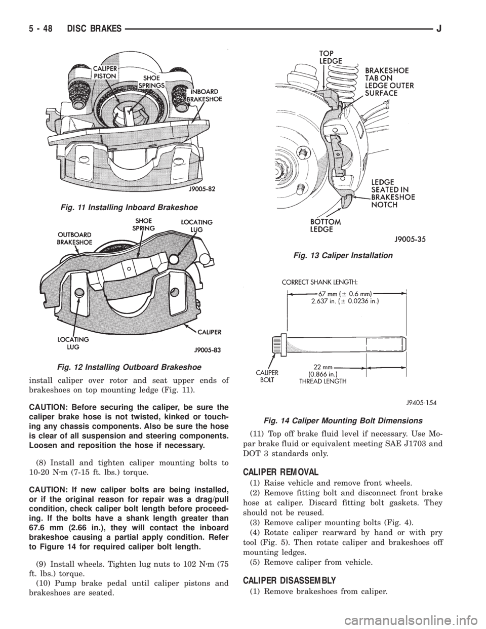
install caliper over rotor and seat upper ends of
brakeshoes on top mounting ledge (Fig. 11).
CAUTION: Before securing the caliper, be sure the
caliper brake hose is not twisted, kinked or touch-
ing any chassis components. Also be sure the hose
is clear of all suspension and steering components.
Loosen and reposition the hose if necessary.
(8) Install and tighten caliper mounting bolts to
10-20 Nzm (7-15 ft. lbs.) torque.
CAUTION: If new caliper bolts are being installed,
or if the original reason for repair was a drag/pull
condition, check caliper bolt length before proceed-
ing. If the bolts have a shank length greater than
67.6 mm (2.66 in.), they will contact the inboard
brakeshoe causing a partial apply condition. Refer
to Figure 14 for required caliper bolt length.
(9) Install wheels. Tighten lug nuts to 102 Nzm (75
ft. lbs.) torque.
(10) Pump brake pedal until caliper pistons and
brakeshoes are seated.(11) Top off brake fluid level if necessary. Use Mo-
par brake fluid or equivalent meeting SAE J1703 and
DOT 3 standards only.
CALIPER REMOVAL
(1) Raise vehicle and remove front wheels.
(2) Remove fitting bolt and disconnect front brake
hose at caliper. Discard fitting bolt gaskets. They
should not be reused.
(3) Remove caliper mounting bolts (Fig. 4).
(4) Rotate caliper rearward by hand or with pry
tool (Fig. 5). Then rotate caliper and brakeshoes off
mounting ledges.
(5) Remove caliper from vehicle.
CALIPER DISASSEMBLY
(1) Remove brakeshoes from caliper.
Fig. 11 Installing Inboard Brakeshoe
Fig. 12 Installing Outboard Brakeshoe
Fig. 13 Caliper Installation
Fig. 14 Caliper Mounting Bolt Dimensions
5 - 48 DISC BRAKESJ
Page 187 of 2198
CALIPER CLEANING AND INSPECTION
Clean the caliper and piston with Mopar brake
cleaner, clean brake fluid, or denatured alcohol only.
Do not use gasoline, kerosene, thinner, or similar sol-
vents. These products leave a residue that will dam-
age pistons and seals.
Wipe the caliper and piston dry with lint free tow-
els or use low pressure compressed air.
Inspect the piston and piston bore. Replace the cal-
iper if the bore is corroded, rusted, pitted, or scored.
Do not hone the caliper piston bore. Replace the cal-
iper if the bore exhibits any of the aforementioned
conditions.
Inspect the caliper piston. The piston is made from
a phenolic resin and should be smooth and clean. Re-
place the piston if cracked, chipped, or scored. Do not
attempt to restore a scored, or corroded piston sur-
face by sanding or polishing. The piston must be re-
placed if damaged.
CAUTION: Never interchange phenolic resin and
steel caliper pistons. The seals, seal grooves, cali-
per bores and piston tolerances are different for
resin and steel pistons. Do not intermix these com-
ponents.
Inspect the caliper mounting bolt bushings and
boots. Replace the boots if cut or torn. Clean and lu-
bricate the bushings with GE 661 or Dow 111 silicone
grease if necessary.
Inspect condition of the caliper mounting bolts. Re-
place the bolts if corroded, rusted, or worn. Do not
reuse the bolts if unsure of their condition.
Length of the caliper mounting bolts is also ex-
tremely important.
Use the replacement bolts specified in the parts
catalog at all times. Do not use substitute bolts. Bolts
that are too long will partially apply the inboard
brakeshoe causing drag and pull. Refer to the caliper
and brakeshoe installation procedures for service de-
tails and bolt dimensions.
CALIPER ASSEMBLY
(1) Coat caliper piston bore, new piston seal and
piston with clean, fresh brake fluid.
(2) Lubricate caliper bushings and interior of bush-
ing boots with GE 661, Dow 111, or Permatex Dielec-
tric silicone grease.
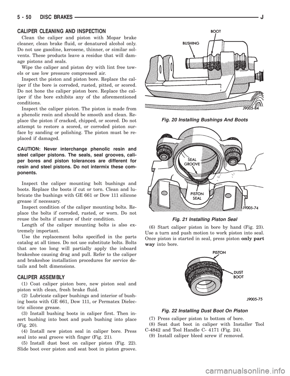
(3) Install bushing boots in caliper first. Then in-
sert bushing into boot and push bushing into place
(Fig. 20).
(4) Install new piston seal in caliper bore. Press
seal into seal groove with finger (Fig. 21).
(5) Install dust boot on caliper piston (Fig. 22).
Slide boot over piston and seat boot in piston groove.(6) Start caliper piston in bore by hand (Fig. 23).
Use a turn and push motion to work piston into seal.
Once piston is started in seal, press pistononly part
wayinto bore.
(7) Press caliper piston to bottom of bore.
(8) Seat dust boot in caliper with Installer Tool
C-4842 and Tool Handle C- 4171 (Fig. 24).
(9) Install caliper bleed screw if removed.
Fig. 20 Installing Bushings And Boots
Fig. 21 Installing Piston Seal
Fig. 22 Installing Dust Boot On Piston
5 - 50 DISC BRAKESJ
Page 299 of 2198
CAUTION: Be certain that battery cables are con-
nected to the correct battery terminals. Reverse po-
larity can damage electrical components.
(12) Place oiled felt washer on battery positive ter-
minal post.
(13) Install and tighten battery positive cable ter-
minal clamp. Then install and tighten negative cableterminal clamp. Both cable clamp bolts require
torque of 8.5 Nzm (75 in. lbs.).
(14) Apply a thin coating of petroleum jelly or
chassis grease to cable terminals and battery posts.
STARTER AND STARTER RELAY
GENERAL INFORMATION
This section covers starter and starter relay service
procedures only. For diagnostic procedures, refer to
Group 8A - Battery/Starting/Charging Systems Diag-
nostics. Service procedures for other starting system
components can be found as follows:
²battery - see Battery, in this group
²ignition switch - refer to Group 8D - Ignition Sys-
tems
²park/neutral position switch (automatic transmis-
sion) - refer to Group 21 - Transmission and Transfer
Case
²wiring harness and connectors - refer to Group 8W
- Wiring Diagrams.
STARTER
The starter motor incorporates several features to
create a reliable, efficient, compact and lightweight
unit. A planetary gear system (intermediate trans-
mission) is used between the electric motor and pin-
ion gear. This feature makes it possible to reduce the
dimensions of the starter. At the same time, it allows
higher armature rotational speed and delivers in-
creased torque through the pinion gear to the fly-
wheel or drive plate ring gear.
The use of a permanent magnet field also reduces
starter size and weight. This field consists of six
high-strength permanent magnets. The magnets are
aligned according to their polarity and are perma-
nently fixed in the starter field frame.
The starter motors for all engines are activated by
a solenoid mounted to the overrunning clutch hous-
ing. However, the starter motor/solenoid are serviced
only as a complete assembly. If either component
fails, the entire assembly must be replaced.
This unit is highly sensitive to hammering, shocks
and external pressure.
CAUTION: The starter motor MUST NOT BE
CLAMPED in a vise by the starter field frame. Doing
so may damage the magnets. It may be clamped by
the mounting flange ONLY.CAUTION: Do not connect starter motor incorrectly
when tests are being performed. The permanent
magnets may be damaged and rendered unservice-
able.
STARTER RELAY
The starter relay is an International Standards Or-
ganization (ISO) type relay, and is located in the
Power Distribution Center (PDC). Refer to underside
of PDC cover for relay location.
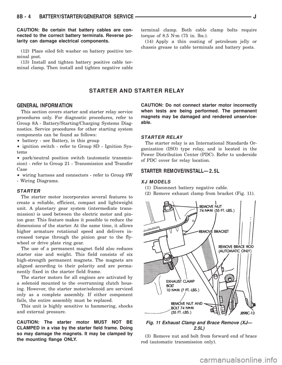
STARTER REMOVE/INSTALLÐ2.5L
XJ MODELS
(1) Disconnect battery negative cable.
(2) Remove exhaust clamp from bracket (Fig. 11).
(3) Remove nut and bolt from forward end of brace
rod (automatic transmission only).
Fig. 11 Exhaust Clamp and Brace Remove (XJÐ
2.5L)
8B - 4 BATTERY/STARTER/GENERATOR SERVICEJ
Page 1133 of 2198
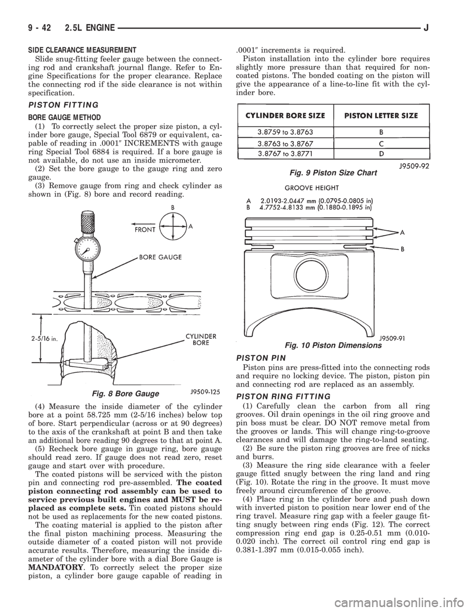
SIDE CLEARANCE MEASUREMENT
Slide snug-fitting feeler gauge between the connect-
ing rod and crankshaft journal flange. Refer to En-
gine Specifications for the proper clearance. Replace
the connecting rod if the side clearance is not within
specification.
PISTON FITTING
BORE GAUGE METHOD
(1) To correctly select the proper size piston, a cyl-
inder bore gauge, Special Tool 6879 or equivalent, ca-
pable of reading in .00019INCREMENTS with gauge
ring Special Tool 6884 is required. If a bore gauge is
not available, do not use an inside micrometer.
(2) Set the bore gauge to the gauge ring and zero
gauge.
(3) Remove gauge from ring and check cylinder as
shown in (Fig. 8) bore and record reading.
(4) Measure the inside diameter of the cylinder
bore at a point 58.725 mm (2-5/16 inches) below top
of bore. Start perpendicular (across or at 90 degrees)
to the axis of the crankshaft at point B and then take
an additional bore reading 90 degrees to that at point A.
(5) Recheck bore gauge in gauge ring, bore gauge
should read zero. If gauge does not read zero, reset
gauge and start over with procedure.
The coated pistons will be serviced with the piston
pin and connecting rod pre-assembled.The coated
piston connecting rod assembly can be used to
service previous built engines and MUST be re-
placed as complete sets.Tin coated pistons should
not be used as replacements for the new coated pistons.
The coating material is applied to the piston after
the final piston machining process. Measuring the
outside diameter of a coated piston will not provide
accurate results. Therefore, measuring the inside di-
ameter of the cylinder bore with a dial Bore Gauge is
MANDATORY. To correctly select the proper size
piston, a cylinder bore gauge capable of reading in.00019increments is required.
Piston installation into the cylinder bore requires
slightly more pressure than that required for non-
coated pistons. The bonded coating on the piston will
give the appearance of a line-to-line fit with the cyl-
inder bore.
PISTON PIN
Piston pins are press-fitted into the connecting rods
and require no locking device. The piston, piston pin
and connecting rod are replaced as an assembly.
PISTON RING FITTING
(1) Carefully clean the carbon from all ring
grooves. Oil drain openings in the oil ring groove and
pin boss must be clear. DO NOT remove metal from
the grooves or lands. This will change ring-to-groove
clearances and will damage the ring-to-land seating.
(2) Be sure the piston ring grooves are free of nicks
and burrs.
(3) Measure the ring side clearance with a feeler
gauge fitted snugly between the ring land and ring
(Fig. 10). Rotate the ring in the groove. It must move
freely around circumference of the groove.
(4) Place ring in the cylinder bore and push down
with inverted piston to position near lower end of the
ring travel. Measure ring gap with a feeler gauge fit-
ting snugly between ring ends (Fig. 12). The correct
compression ring end gap is 0.25-0.51 mm (0.010-
0.020 inch). The correct oil control ring end gap is
0.381-1.397 mm (0.015-0.055 inch).
Fig. 8 Bore Gauge
Fig. 9 Piston Size Chart
Fig. 10 Piston Dimensions
9 - 42 2.5L ENGINEJ
Page 1175 of 2198
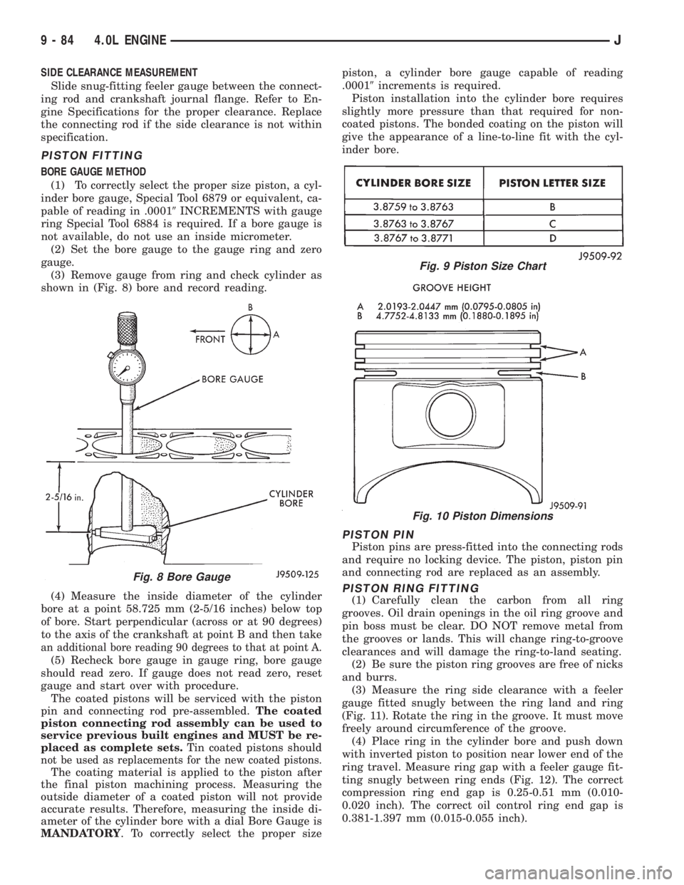
SIDE CLEARANCE MEASUREMENT
Slide snug-fitting feeler gauge between the connect-
ing rod and crankshaft journal flange. Refer to En-
gine Specifications for the proper clearance. Replace
the connecting rod if the side clearance is not within
specification.
PISTON FITTING
BORE GAUGE METHOD
(1) To correctly select the proper size piston, a cyl-
inder bore gauge, Special Tool 6879 or equivalent, ca-
pable of reading in .00019INCREMENTS with gauge
ring Special Tool 6884 is required. If a bore gauge is
not available, do not use an inside micrometer.
(2) Set the bore gauge to the gauge ring and zero
gauge.
(3) Remove gauge from ring and check cylinder as
shown in (Fig. 8) bore and record reading.
(4) Measure the inside diameter of the cylinder
bore at a point 58.725 mm (2-5/16 inches) below top
of bore. Start perpendicular (across or at 90 degrees)
to the axis of the crankshaft at point B and then take
an additional bore reading 90 degrees to that at point A.
(5) Recheck bore gauge in gauge ring, bore gauge
should read zero. If gauge does not read zero, reset
gauge and start over with procedure.
The coated pistons will be serviced with the piston
pin and connecting rod pre-assembled.The coated
piston connecting rod assembly can be used to
service previous built engines and MUST be re-
placed as complete sets.Tin coated pistons should
not be used as replacements for the new coated pistons.
The coating material is applied to the piston after
the final piston machining process. Measuring the
outside diameter of a coated piston will not provide
accurate results. Therefore, measuring the inside di-
ameter of the cylinder bore with a dial Bore Gauge is
MANDATORY. To correctly select the proper sizepiston, a cylinder bore gauge capable of reading
.00019increments is required.
Piston installation into the cylinder bore requires
slightly more pressure than that required for non-
coated pistons. The bonded coating on the piston will
give the appearance of a line-to-line fit with the cyl-
inder bore.
PISTON PIN
Piston pins are press-fitted into the connecting rods
and require no locking device. The piston, piston pin
and connecting rod are replaced as an assembly.
PISTON RING FITTING
(1) Carefully clean the carbon from all ring
grooves. Oil drain openings in the oil ring groove and
pin boss must be clear. DO NOT remove metal from
the grooves or lands. This will change ring-to-groove
clearances and will damage the ring-to-land seating.
(2) Be sure the piston ring grooves are free of nicks
and burrs.
(3) Measure the ring side clearance with a feeler
gauge fitted snugly between the ring land and ring
(Fig. 11). Rotate the ring in the groove. It must move
freely around circumference of the groove.
(4) Place ring in the cylinder bore and push down
with inverted piston to position near lower end of the
ring travel. Measure ring gap with a feeler gauge fit-
ting snugly between ring ends (Fig. 12). The correct
compression ring end gap is 0.25-0.51 mm (0.010-
0.020 inch). The correct oil control ring end gap is
0.381-1.397 mm (0.015-0.055 inch).
Fig. 8 Bore Gauge
Fig. 9 Piston Size Chart
Fig. 10 Piston Dimensions
9 - 84 4.0L ENGINEJ
Page 1198 of 2198
FRAME AND BUMPERS
CONTENTS
page page
BUMPERS.............................. 5
BUMPERS............................. 16FRAME................................. 1
FRAME................................ 10
FRAME
INDEX
page page
Frame Dimensions......................... 1
Front Skid Plate........................... 1
Fuel Filler Hose Splash ShieldÐXJ Vehicles...... 4
Fuel Tank Skid Plate........................ 3Fuel Tank Support Strap..................... 4
General Information........................ 1
Transfer Case Skid Plate.................... 3
GENERAL INFORMATION
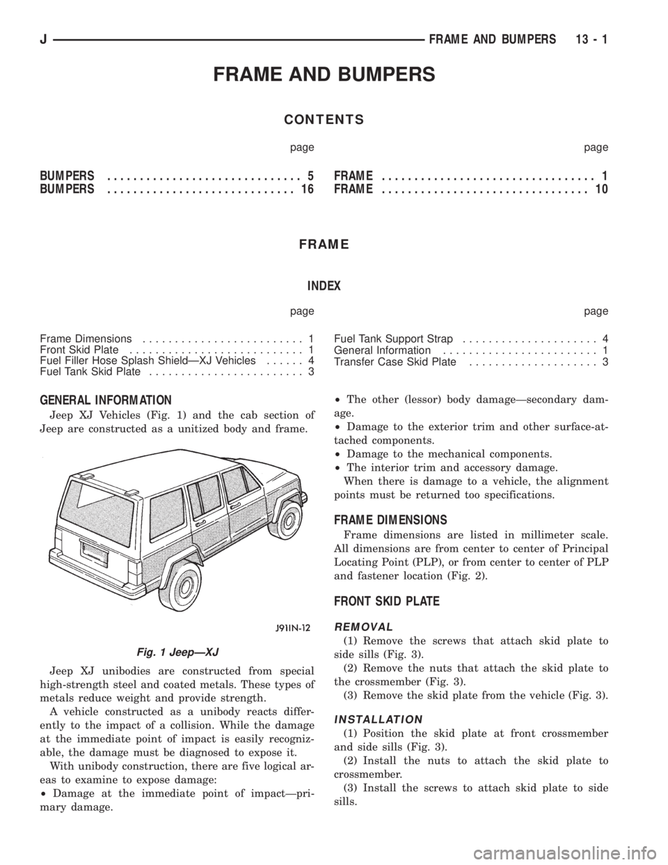
Jeep XJ Vehicles (Fig. 1) and the cab section of
Jeep are constructed as a unitized body and frame.
Jeep XJ unibodies are constructed from special
high-strength steel and coated metals. These types of
metals reduce weight and provide strength.
A vehicle constructed as a unibody reacts differ-
ently to the impact of a collision. While the damage
at the immediate point of impact is easily recogniz-
able, the damage must be diagnosed to expose it.
With unibody construction, there are five logical ar-
eas to examine to expose damage:
²Damage at the immediate point of impactÐpri-
mary damage.²The other (lessor) body damageÐsecondary dam-
age.
²Damage to the exterior trim and other surface-at-
tached components.
²Damage to the mechanical components.
²The interior trim and accessory damage.
When there is damage to a vehicle, the alignment
points must be returned too specifications.
FRAME DIMENSIONS
Frame dimensions are listed in millimeter scale.
All dimensions are from center to center of Principal
Locating Point (PLP), or from center to center of PLP
and fastener location (Fig. 2).
FRONT SKID PLATE
REMOVAL
(1) Remove the screws that attach skid plate to
side sills (Fig. 3).
(2) Remove the nuts that attach the skid plate to
the crossmember (Fig. 3).
(3) Remove the skid plate from the vehicle (Fig. 3).
INSTALLATION
(1) Position the skid plate at front crossmember
and side sills (Fig. 3).
(2) Install the nuts to attach the skid plate to
crossmember.
(3) Install the screws to attach skid plate to side
sills.
Fig. 1 JeepÐXJ
JFRAME AND BUMPERS 13 - 1
Page 1199 of 2198
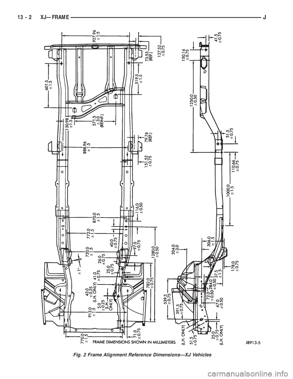
Fig. 2 Frame Alignment Reference DimensionsÐXJ Vehicles
13 - 2 XJÐFRAMEJ
Page 1207 of 2198
FRAME
INDEX
page page
Frame Dimensions........................ 13
Frame Repairs........................... 13
Frame Straightening....................... 13
Fuel Tank Skid Plate....................... 15
General Information....................... 10Generator Splash Shield.................... 13
Safety Precautions and Warnings............. 10
Tow Hooks.............................. 13
Transfer Case Skid Plate.................... 15
SAFETY PRECAUTIONS AND WARNINGS
WARNING: USE EYE PROTECTION WHEN GRIND-
ING OR WELDING METAL, SERIOUS EYE INJURY
CAN RESULT.
BEFORE PROCEEDING WITH FRAME REPAIR IN-
VOLVING GRINDING OR WELDING, VERIFY THAT
VEHICLE FUEL SYSTEM IS NOT LEAKING OR IN
CONTACT WITH REPAIR AREA, PERSONAL INJURY
CAN RESULT.
DO NOT ALLOW OPEN FLAME TO CONTACT
PLASTIC BODY PANELS. FIRE OR EXPLOSION CAN
RESULT.
WHEN WELDED FRAME COMPONENTS ARE RE-
PLACED, 100% PENETRATION WELD MUST BE
ACHIEVED DURING INSTALLATION. IF NOT, DAN-
GEROUS OPERATING CONDITIONS CAN RESULT.
STAND CLEAR OF CABLES OR CHAINS ON
PULLING EQUIPMENT DURING FRAME STRAIGHT-
ENING OPERATIONS, PERSONAL INJURY CAN RE-
SULT.
DO NOT VENTURE UNDER A HOISTED VEHICLE
THAT IS NOT SUPPORTED ON SAFETY STANDS,
PERSONAL INJURY CAN RESULT.
CAUTION: Do not reuse damaged fasteners, quality
of repair would be suspect.
Do not drill holes in top or bottom frame rail
flanges, frame rail failure can result.
Do Not use softer than Grade 3 bolts to replace
production fasteners, loosening or failure can re-
sult.When using heat to straighten frame components
do not exceed 566ÉC (1050ÉF), metal fatigue can re-
sult.
Welding the joints around riveted cross members
and frame side rails can weaken frame
GENERAL INFORMATION
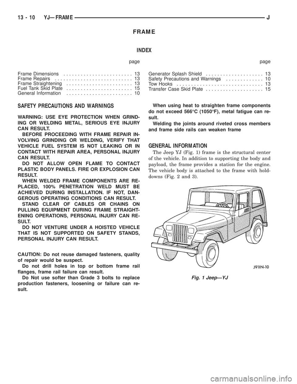
The Jeep YJ (Fig. 1) frame is the structural center
of the vehicle. In addition to supporting the body and
payload, the frame provides a station for the engine.
The vehicle body is attached to the frame with hold-
downs (Fig. 2 and 3).
Fig. 1 JeepÐYJ
13 - 10 YJÐFRAMEJ
Page 1210 of 2198
The frame is constructed of high-strength channel
steel siderails and crossmembers. The crossmembers
join the siderails and retain them in alignment in re-
lation to each other. This provides resistance to
frame twists and strains.
FRAME STRAIGHTENING
When necessary, a conventional frame that is bent
or twisted can be straightened by application of heat.
The temperature must not exceed 566ÉC (1050ÉF).
The use of a specially designed heat crayon can de-
termine the desired temperature. Excessive heat will
decrease the strength of the metal and result in a
weakened frame.
Welding the joints around riveted cross members
and frame side rails is not recommended.
A straightening repair process should be limited to
frame members that are not severely damaged.
FRAME REPAIRS
DRILLING HOLES
Do not drill holes in frame side rail top and bottom
flanges, metal fatigue can result causing frame fail-
ure. Holes drilled in the side of the frame rail must
be at least 38 mm (1.5 in.) from the top and bottom
flanges.
Additional drill holes should be located away from
existing holes.
WELDING
Use MIG, TIG or arc welding equipment to repair
welded frame components.
Frame components that have been damaged should
be inspected for cracks before returning the vehicle
to use. If cracks are found in accessible frame com-
ponents perform the following procedures.
(1) Drill a hole at each end of the crack with a 3
mm (O.125 in.) diameter drill bit.
(2) Using a suitable die grinder with 3 inch cut off
wheel, V-groove the crack to allow 100% weld pene-
tration.
(3) Weld the crack.
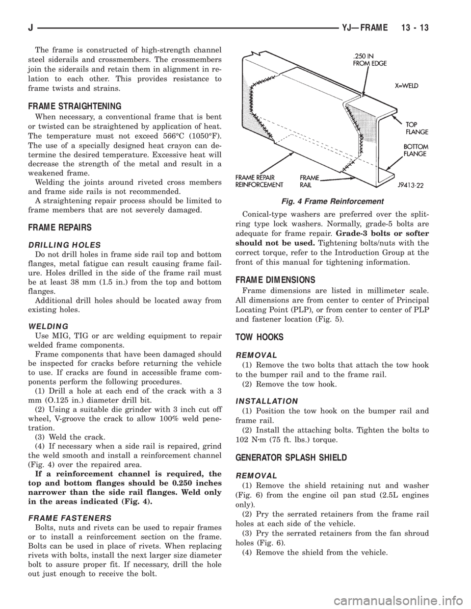
(4) If necessary when a side rail is repaired, grind
the weld smooth and install a reinforcement channel
(Fig. 4) over the repaired area.
If a reinforcement channel is required, the
top and bottom flanges should be 0.250 inches
narrower than the side rail flanges. Weld only
in the areas indicated (Fig. 4).
FRAME FASTENERS
Bolts, nuts and rivets can be used to repair frames
or to install a reinforcement section on the frame.
Bolts can be used in place of rivets. When replacing
rivets with bolts, install the next larger size diameter
bolt to assure proper fit. If necessary, drill the hole
out just enough to receive the bolt.Conical-type washers are preferred over the split-
ring type lock washers. Normally, grade-5 bolts are
adequate for frame repair.Grade-3 bolts or softer
should not be used.Tightening bolts/nuts with the
correct torque, refer to the Introduction Group at the
front of this manual for tightening information.
FRAME DIMENSIONS
Frame dimensions are listed in millimeter scale.
All dimensions are from center to center of Principal
Locating Point (PLP), or from center to center of PLP
and fastener location (Fig. 5).
TOW HOOKS
REMOVAL
(1) Remove the two bolts that attach the tow hook
to the bumper rail and to the frame rail.
(2) Remove the tow hook.
INSTALLATION
(1) Position the tow hook on the bumper rail and
frame rail.
(2) Install the attaching bolts. Tighten the bolts to
102 Nzm (75 ft. lbs.) torque.
GENERATOR SPLASH SHIELD
REMOVAL
(1) Remove the shield retaining nut and washer
(Fig. 6) from the engine oil pan stud (2.5L engines
only).
(2) Pry the serrated retainers from the frame rail
holes at each side of the vehicle.
(3) Pry the serrated retainers from the fan shroud
holes (Fig. 6).
(4) Remove the shield from the vehicle.
Fig. 4 Frame Reinforcement
JYJÐFRAME 13 - 13