door JEEP CHEROKEE 1995 Service Repair Manual
[x] Cancel search | Manufacturer: JEEP, Model Year: 1995, Model line: CHEROKEE, Model: JEEP CHEROKEE 1995Pages: 2198, PDF Size: 82.83 MB
Page 2 of 2198
LUBRICATION AND MAINTENANCE
CONTENTS
page page
CHASSIS AND BODY COMPONENTS........ 28
DRIVETRAIN........................... 22
ENGINE MAINTENANCE................... 15GENERAL INFORMATION.................. 1
JUMP STARTING, TOWING AND HOISTING.... 9
MAINTENANCE SCHEDULES................ 4
GENERAL INFORMATION
INDEX
page page
Classification of Lubricants................... 2
Components Requiring No Lubrication........... 2
Fluid Capacities........................... 3
Fuel Requirements......................... 1International Symbols....................... 1
Introduction.............................. 1
Lubrication and Replacement Parts
Recommendation......................... 2
INTRODUCTION
Lubrication and maintenance is divided into re-
quired and recommended service tasks. The required
service tasks must be completed to verify the emis-
sion controls function correctly. The recommended
service tasks should be completed to maintain safety
and durability.
This information will assist the service personnel
in providing maximum protection for each owner's
vehicle.
Conditions can vary with individual driving habits.
It is necessary to schedule maintenance as a time in-
terval as well as a distance interval.
It is the owner's responsibility to determine the ap-
plicable driving condition. Also to have the vehicle
serviced according to the maintenance schedule, and
to pay for the necessary parts and labor.
Additional maintenance and lubrication informa-
tion is listed in the Owner's Manual.
INTERNATIONAL SYMBOLS
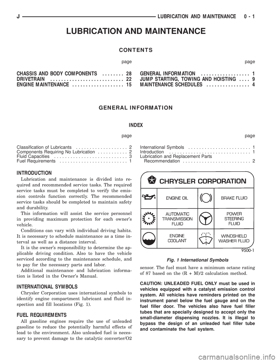
Chrysler Corporation uses international symbols to
identify engine compartment lubricant and fluid in-
spection and fill locations (Fig. 1).
FUEL REQUIREMENTS
All gasoline engines require the use of unleaded
gasoline to reduce the potentially harmful effects of
lead to the environment. Also unleaded fuel is neces-
sary to prevent damage to the catalytic converter/O2sensor. The fuel must have a minimum octane rating
of 87 based on the (R + M)/2 calculation method.
CAUTION: UNLEADED FUEL ONLY must be used in
vehicles equipped with a catalyst emission control
system. All vehicles have reminders printed on the
instrument panel below the fuel gauge and on the
fuel filler door. The vehicles also have fuel filler
tubes that are specially designed to accept only the
small-diameter dispensing nozzles. It is illegal to
bypass the design of an unleaded fuel filler tube
and contaminate the fuel system.
Fig. 1 International Symbols
JLUBRICATION AND MAINTENANCE 0 - 1
Page 33 of 2198
(2) Note any indication of drum/rotor overheating,
wheel dragging or the vehicle pulling to one side
when the brakes are applied.
(3) Evaluate any performance complaints received
from the owner/operator.
(4) Repair the brake system as necessary. Refer to
Group, 5 Brakes for additional information and ser-
vice procedures.
TIRES
RECOMMENDED MAINTENANCE
The general condition of the tires and the inflation
pressures should be inspected at the same time the
engine oil is changed and the oil filter is replaced.
In addition, the tires/wheels should be rotated at
the intervals described in the Maintenance Schedules
section of this group.
INSPECTION
Inspect the tires for excessive wear, damage, etc.
Test the tires for the recommended inflation pres-sure. Refer to the tire inflation pressure decal located
on the inside of the glove box door, and also to Group
22, Tires And Wheels.
ROTATION
Refer to Group 22, Tires And Wheels for the recom-
mended method of tire/wheel rotation for a Jeep ve-
hicle.
BODY COMPONENTS
LUBRICATION REQUIREMENTS
All Jeep operating mechanisms and linkages
should be lubricated when necessary. The door
weatherstrip seals should be lubricated to prolong
their life as well as to improve door sealing.
LUBRICANT SPECIFICATIONS
All applicable exterior and interior vehicle operat-
ing mechanisms should be:
²Inspected
²Cleaned
²Pivot/sliding contact areas on the mechanisms
should then be lubricated.
Multi-purpose NLGI GC-LB MOPAR Multi-Mileage
Lubricant or an equivalent, should be used to lubri-
cate the mechanisms. The door weatherstrip seals
should be lubricated with silicone lubricant spray.
Refer to the Body Lubricant Specifications chart be-
low for additional lubricant applications.
LUBRICATION
All pivoting and sliding contact areas, should be lu-
bricated periodically to ensure quiet, easy operation
and to protect against wear and corrosion. Areas in-
clude:
²Seat tracks.
²Door hinges/latches/strikers.
²Liftgate/tailgate/hood hinges (Fig. 11).
(1) As required, lubricate the body components
with the specified lubricants.
(2) Apply silicone lubricant to a cloth and wipe it
on door seals to avoid over-spray that can soil pas-
senger clothing.
(3) Before applying lubricant, the component
should be wiped clean. After lubrication, any excess
lubricant should be removed.
(4) The door lock cylinders should be lubricated 2
times each year (preferably autumn and spring):
²Spray a small amount of lock cylinder lubricant di-
rectly into the lock cylinder.
²Apply a small amount to the key and insert it into
the lock cylinder.
²Rotate it to the locked position and then back to
the unlocked position several times.
²Remove the key. Wipe the lubricant from it with a
clean cloth to avoid soiling of clothing.
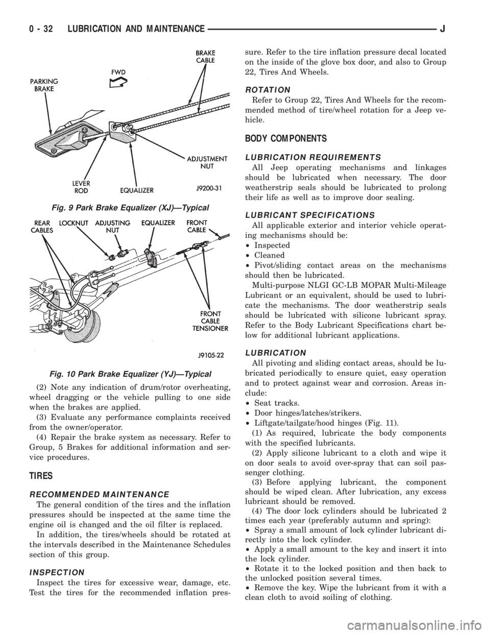
Fig. 9 Park Brake Equalizer (XJ)ÐTypical
Fig. 10 Park Brake Equalizer (YJ)ÐTypical
0 - 32 LUBRICATION AND MAINTENANCEJ
Page 281 of 2198
IGNITION-OFF DRAW
GENERAL INFORMATION
Ignition-Off Draw (IOD) refers to power being
drained from the battery with the ignition switch
turned OFF. A normal vehicle electrical system will
draw from 5 to 20 milliamps (0.005 - 0.020 amps).
This is with the ignition switch in the OFF position,
and all non-ignition controlled circuits in proper
working order. The 20 milliamps are needed to sup-
ply PCM memory, digital clock memory, and electron-
ically-tuned radio memory.
A vehicle that has not been operated for approxi-
mately 20 days, may discharge the battery to an in-
adequate level. When a vehicle will not be used for
20 days or more (stored), remove the IOD fuse in the
Power Distribution Center (PDC). This will reduce
battery discharging.
Excessive battery drain can be caused by:
²electrical items left on
²faulty or improperly adjusted switches
²internally shorted generator
²intermittent shorts in the wiring.
If the IOD is over 20 milliamps, the problem must
be found and corrected before replacing a battery. In
most cases, the battery can be charged and returned
to service.
DIAGNOSIS
Testing for high-amperage IOD must be per-
formed first to prevent damage to most milli-
amp meters.
(1) Verify that all electrical accessories are off.
Turn off all lamps, remove ignition key, and close all
doors. If the vehicle is equipped with illuminated en-
try or electronically-tuned radio, allow the systems to
automatically shut off (time out). This may take up
to 3 minutes.
(2) Determine that the underhood lamp is operat-
ing properly, then disconnect or remove bulb.
(3) Disconnect negative cable from battery.
(4) Connect a typical 12-volt test lamp (low-watt-
age bulb) between the negative cable clamp and the
battery negative terminal. Make sure that the doors
remain closed so that illuminated entry is not acti-
vated.The test lamp may light brightly for up to 3 min-
utes, or may not light at all, depending upon the ve-
hicle's electrical equipment. The term brightly, as
used throughout the following tests, implies the
brightness of the test lamp will be the same as if it
were connected across the battery.
The test lamp must be securely clamped to the neg-
ative cable clamp and battery negative terminal. If
the test lamp becomes disconnected during any part
of the IOD test, the electronic timer function will be
activated and all tests must be repeated.
(5) After 3 minutes the test lamp should turn off
or be dimly lit, depending upon the vehicle's electri-
cal equipment. If the test lamp remains brightly lit,
do not disconnect it. Remove each fuse or circuit
breaker (refer to Group 8W - Wiring Diagrams) until
test lamp is either off or dimly lit. This will isolate
each circuit and identify the source of the high-am-
perage draw.
If the test lamp is still brightly lit after disconnect-
ing each fuse and circuit breaker, disconnect the wir-
ing harness from the generator. If test lamp now
turns off or is dimly lit, see Charging System in this
group to diagnose faulty generator. Do not disconnect
the test lamp.
After high-amperage IOD has been corrected, low-
amperage IOD may be checked. It is now safe to in-
stall a milliamp meter to check for low- amperage
IOD.
(6) With test lamp still connected securely, clamp a
milliamp meter between battery negative terminal
and negative cable clamp.
Do not open any doors or turn on any electri-
cal accessories with the test lamp disconnected
or the milliamp meter may be damaged.
(7) Disconnect test lamp. Observe milliamp meter.
The current draw should not exceed 0.020 amp. If
draw exceeds 20 milliamps, isolate each circuit by re-
moving circuit breakers and fuses. The milliamp
meter reading will drop when the source of the draw
is disconnected. Repair this circuit as necessary,
whether a wiring short, incorrect switch adjustment
or a component failure is found.
8A - 10 BATTERY/STARTING/CHARGING SYSTEMS DIAGNOSTICSJ
Page 304 of 2198
OVERHEAD CONSOLE
CONTENTS
page page
DIAGNOSIS............................. 2
GENERAL INFORMATION.................. 1SERVICE PROCEDURES................... 5
GENERAL INFORMATION
An overhead console featuring an electronic com-
pass and thermometer is an available option for XJ
(Cherokee) models. Following are general descrip-
tions of major components used in the overhead con-
sole. Refer to Group 8W - Wiring Diagrams for
complete circuit descriptions and diagrams.
COMPASS
The compass will display the direction in which the
vehicle is pointed using the eight major compass
headings (Examples: north is N, northeast is NE). It
does not display the headings in actual degrees. The
display is turned on or off using the COMP/TEMP
button to the left of the display.
The self-calibrating compass unit requires no ad-
justing in normal use. The only calibration that may
prove necessary is to drive the vehicle in 3 complete
circles, on level ground, in not less than 48 seconds.
This will reorient the unit to its vehicle.
The unit also will compensate for magnetism the
body of the vehicle may acquire during normal use.
However, avoid placing anything magnetic directly on
the roof of the vehicle. Magnetic mounts for an an-
tenna, a repair order hat or a funeral procession flag
can exceed the compensating ability of the compass
unit if placed on the roof panel. Magnetic bit drivers
used on the fasteners that hold the assembly to the
roof header can also affect compass operation.
If the vehicle roof should become magnetized, the
demagnetizing and calibration procedures may be re-
quired to restore proper operation.
THERMOMETER
The thermometer displays the outside ambient
temperature. The temperature displayed can be
changed from Fahrenheit to Celsius using the US/
METRIC button. The displayed temperature is not
an instant reading of conditions, but an average tem-
perature. It may take the unit several minutes to re-
act to a major temperature change such as driving
out of a heated garage into winter temperatures.
When the ignition switch is turned OFF, the lastdisplayed temperature reading stays in memory.
When the ignition switch is turned ON again, the
thermometer will display the memory temperature
for one minute; then update the display to the cur-
rent average temperature reading within five min-
utes.
READING AND COURTESY LAMPS
All reading and courtesy lamps in the overhead
console are activated by the door jamb switches.
When all doors and the liftgate are closed, the lamps
can be individually activated by depressing the corre-
sponding lens. When a door and/or the liftgate is
open, depressing the lamp lens switches will not turn
the lamps off. Refer to Group 8L - Lamps, for diag-
nosis and service of these lamps.
KEYLESS ENTRY RECEIVER
The overhead console houses the keyless entry re-
ceiver. Refer to Group 8P - Power Locks, for diagno-
sis and service of this component.
REMOTE GARAGE DOOR OPENER STORAGE
A compartment in the overhead console is designed
to hold most remote garage door opener transmitters.
The transmitter is mounted within the compartment
with an adhesive-backed hook and loop fastener
patch. Then one to three pegs are selected and
mounted on a post on the inside of the storage com-
partment door. The pegs may be stacked, if neces-
sary. The peg(s) selected must be long enough to
activate the button of the transmitter each time the
storage compartment door is depressed.
SUNGLASSES STORAGE
A flocked storage compartment for sunglasses is in-
cluded in the overhead console. This compartment
features a push/push-type latch and a viscous damp-
ening system for a fluid opening motion.
JOVERHEAD CONSOLE 8C - 1
Page 310 of 2198
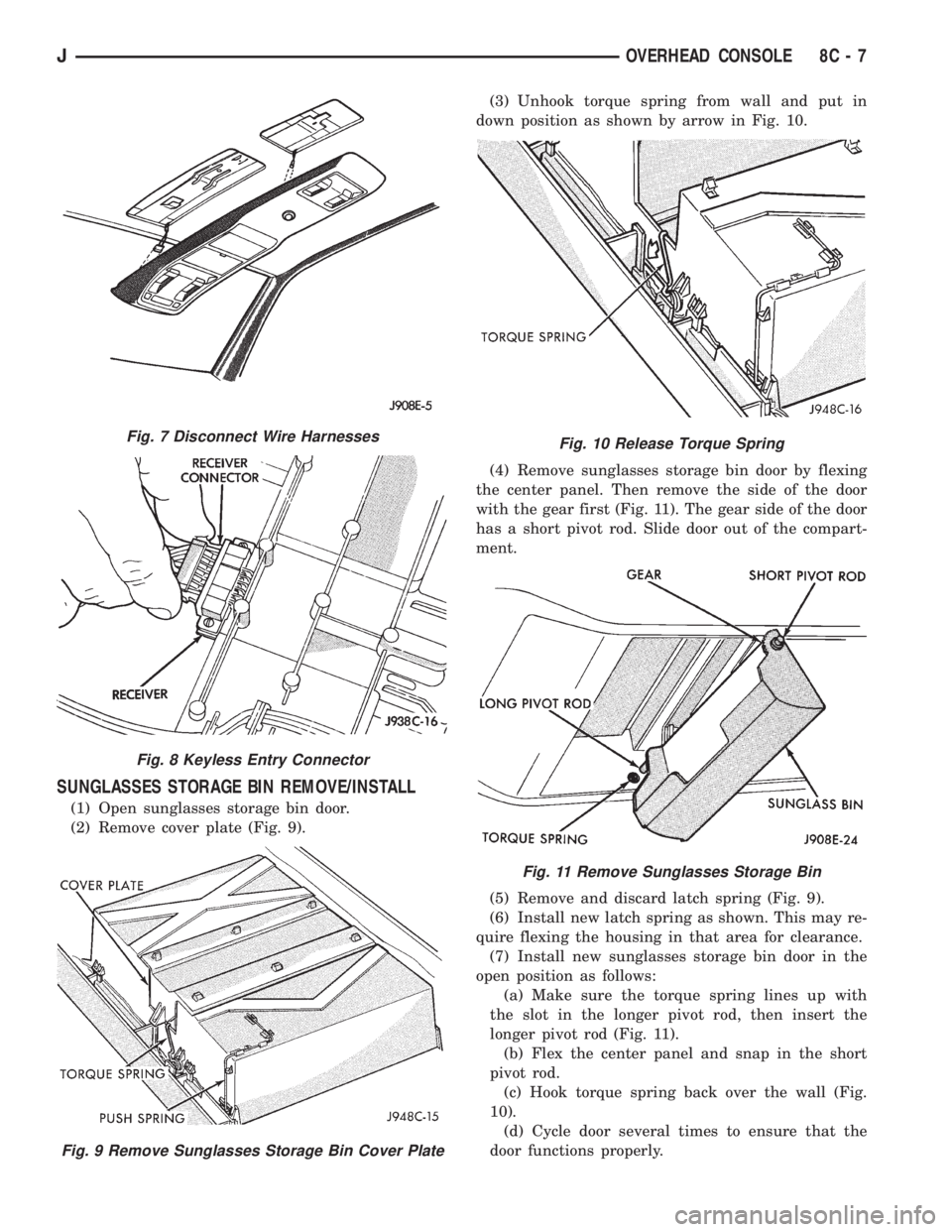
SUNGLASSES STORAGE BIN REMOVE/INSTALL
(1) Open sunglasses storage bin door.
(2) Remove cover plate (Fig. 9).(3) Unhook torque spring from wall and put in
down position as shown by arrow in Fig. 10.
(4) Remove sunglasses storage bin door by flexing
the center panel. Then remove the side of the door
with the gear first (Fig. 11). The gear side of the door
has a short pivot rod. Slide door out of the compart-
ment.
(5) Remove and discard latch spring (Fig. 9).
(6) Install new latch spring as shown. This may re-
quire flexing the housing in that area for clearance.
(7) Install new sunglasses storage bin door in the
open position as follows:
(a) Make sure the torque spring lines up with
the slot in the longer pivot rod, then insert the
longer pivot rod (Fig. 11).
(b) Flex the center panel and snap in the short
pivot rod.
(c) Hook torque spring back over the wall (Fig.
10).
(d) Cycle door several times to ensure that the
door functions properly.
Fig. 7 Disconnect Wire Harnesses
Fig. 8 Keyless Entry Connector
Fig. 9 Remove Sunglasses Storage Bin Cover Plate
Fig. 10 Release Torque Spring
Fig. 11 Remove Sunglasses Storage Bin
JOVERHEAD CONSOLE 8C - 7
Page 388 of 2198

AUDIO SYSTEMS
CONTENTS
page page
DIAGNOSIS............................. 2
GENERAL INFORMATION.................. 1SERVICE PROCEDURES................... 6
GENERAL INFORMATION
Following are general descriptions of major compo-
nents used in XJ (Cherokee)/YJ (Wrangler) audio sys-
tems. Refer to Group 8W - Wiring Diagrams for
complete circuit descriptions and diagrams.
RADIOS
Radio options for the XJ and YJ models include an
AM/FM stereo or an AM/FM stereo/cassette receiver.
Both units are Electronically-Tuned Radios (ETR)
and include a clock function. For more information
on radio features, setting procedures, and control
functions refer to the owner's manual.
IN-LINE FUSE
Each radio receives fused battery feed when the ig-
nition switch is in the ON or ACCESSORY position.
There is an additional in-line fuse in the back of the
radio chassis. The in-line fuse (Fig. 1) will blow to
protect the vehicle electrical system in the event of
internal radio failure.
IGNITION-OFF DRAW FUSE
All vehicles are equipped with an Ignition-Off
Draw (IOD) fuse that is removed when the vehicle is
shipped from the factory. This fuse feeds various ac-
cessories that require current when the ignition
switch is in the OFF position, including the clock and
radio station preset memory functions. The fuse is re-
moved to prevent battery discharge during vehicle
storage.The IOD fuse should be checked if the radio station
preset memory or clock functions are erratic or inop-
erative. The IOD fuse is located in the Power Distri-
bution Center (PDC). Refer to underside of PDC
cover for IOD fuse identification.
RADIO ILLUMINATION RELAY
All radios are connected to a radio illumination re-
lay. The relay controls the source of battery feed for
radio/clock display illumination.
When the park and headlamp switch is in the OFF
position, the radio illumination relay remains de-en-
ergized. The radio/clock display receives full battery
voltage through the normally closed contacts of the
relay. This results in the radio/clock display being il-
luminated at full brightness for easier visibility in
daylight.
When the park and headlamp switch is in the ON
position, the radio illumination relay coil is ener-
gized. With the relay coil energized, the normally
closed contacts of the relay open, and the normally
open contacts of the relay close. This causes the ra-
dio/clock display to receive battery feed through the
instrument panel dimmer switch. The display illumi-
nation brightness can now be adjusted with other
panel lamps for night visibility.
SPEAKERS
Speaker system options include two, four or six (XJ
only) speaker locations. On XJ model two-speaker
systems, one speaker is located in each front door.
Four-speaker systems add one speaker at each end of
a rear-mounted overhead sound bar. The premium
six-speaker option upgrades all the speakers in the
above locations, and adds one tweeter at each end of
the lower instrument panel.
On YJ model two-speaker systems, one speaker is
located at each end of the instrument panel. Four-
speaker systems add one speaker at each end of a
rear-mounted overhead sound bar.
Fig. 1 In-Line Fuse
JAUDIO SYSTEMS 8F - 1
Page 394 of 2198
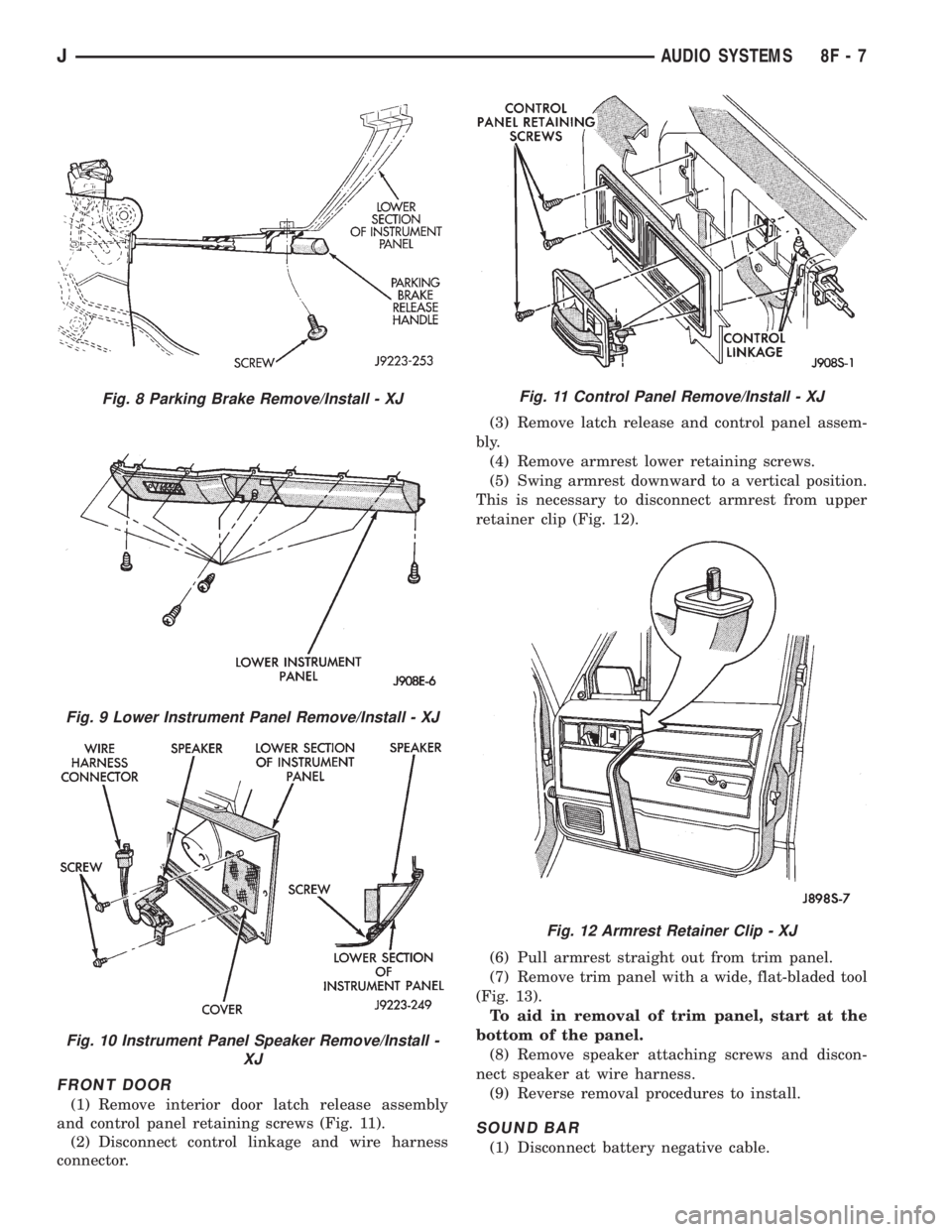
FRONT DOOR
(1) Remove interior door latch release assembly
and control panel retaining screws (Fig. 11).
(2) Disconnect control linkage and wire harness
connector.(3) Remove latch release and control panel assem-
bly.
(4) Remove armrest lower retaining screws.
(5) Swing armrest downward to a vertical position.
This is necessary to disconnect armrest from upper
retainer clip (Fig. 12).
(6) Pull armrest straight out from trim panel.
(7) Remove trim panel with a wide, flat-bladed tool
(Fig. 13).
To aid in removal of trim panel, start at the
bottom of the panel.
(8) Remove speaker attaching screws and discon-
nect speaker at wire harness.
(9) Reverse removal procedures to install.
SOUND BAR
(1) Disconnect battery negative cable.
Fig. 8 Parking Brake Remove/Install - XJ
Fig. 9 Lower Instrument Panel Remove/Install - XJ
Fig. 10 Instrument Panel Speaker Remove/Install -
XJ
Fig. 11 Control Panel Remove/Install - XJ
Fig. 12 Armrest Retainer Clip - XJ
JAUDIO SYSTEMS 8F - 7
Page 459 of 2198
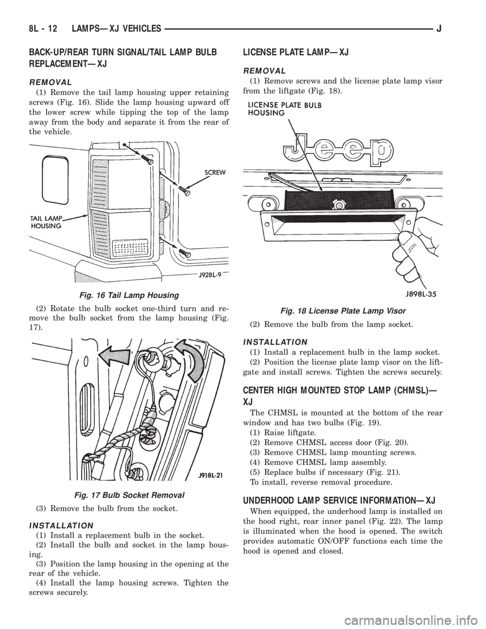
BACK-UP/REAR TURN SIGNAL/TAIL LAMP BULB
REPLACEMENTÐXJ
REMOVAL
(1) Remove the tail lamp housing upper retaining
screws (Fig. 16). Slide the lamp housing upward off
the lower screw while tipping the top of the lamp
away from the body and separate it from the rear of
the vehicle.
(2) Rotate the bulb socket one-third turn and re-
move the bulb socket from the lamp housing (Fig.
17).
(3) Remove the bulb from the socket.
INSTALLATION
(1) Install a replacement bulb in the socket.
(2) Install the bulb and socket in the lamp hous-
ing.
(3) Position the lamp housing in the opening at the
rear of the vehicle.
(4) Install the lamp housing screws. Tighten the
screws securely.
LICENSE PLATE LAMPÐXJ
REMOVAL
(1) Remove screws and the license plate lamp visor
from the liftgate (Fig. 18).
(2) Remove the bulb from the lamp socket.
INSTALLATION
(1) Install a replacement bulb in the lamp socket.
(2) Position the license plate lamp visor on the lift-
gate and install screws. Tighten the screws securely.
CENTER HIGH MOUNTED STOP LAMP (CHMSL)Ð
XJ
The CHMSL is mounted at the bottom of the rear
window and has two bulbs (Fig. 19).
(1) Raise liftgate.
(2) Remove CHMSL access door (Fig. 20).
(3) Remove CHMSL lamp mounting screws.
(4) Remove CHMSL lamp assembly.
(5) Replace bulbs if necessary (Fig. 21).
To install, reverse removal procedure.
UNDERHOOD LAMP SERVICE INFORMATIONÐXJ
When equipped, the underhood lamp is installed on
the hood right, rear inner panel (Fig. 22). The lamp
is illuminated when the hood is opened. The switch
provides automatic ON/OFF functions each time the
hood is opened and closed.
Fig. 16 Tail Lamp Housing
Fig. 17 Bulb Socket Removal
Fig. 18 License Plate Lamp Visor
8L - 12 LAMPSÐXJ VEHICLESJ
Page 460 of 2198
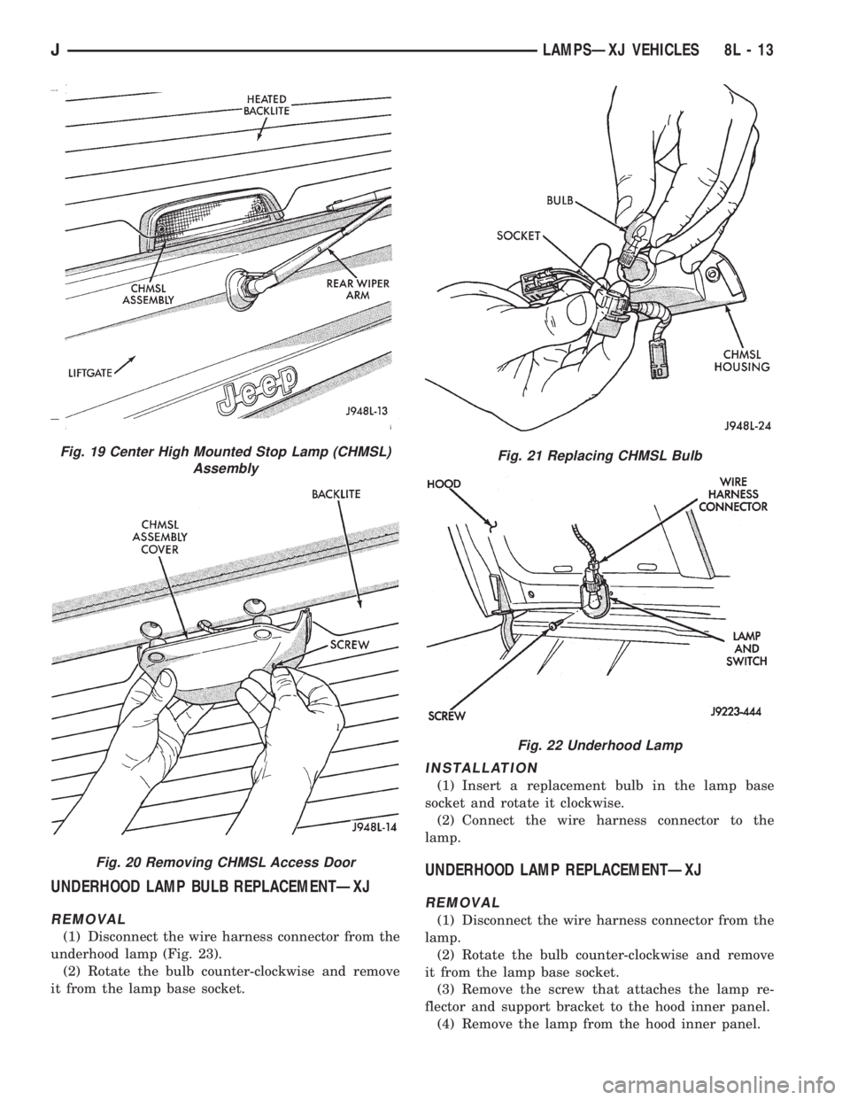
UNDERHOOD LAMP BULB REPLACEMENTÐXJ
REMOVAL
(1) Disconnect the wire harness connector from the
underhood lamp (Fig. 23).
(2) Rotate the bulb counter-clockwise and remove
it from the lamp base socket.
INSTALLATION
(1) Insert a replacement bulb in the lamp base
socket and rotate it clockwise.
(2) Connect the wire harness connector to the
lamp.
UNDERHOOD LAMP REPLACEMENTÐXJ
REMOVAL
(1) Disconnect the wire harness connector from the
lamp.
(2) Rotate the bulb counter-clockwise and remove
it from the lamp base socket.
(3) Remove the screw that attaches the lamp re-
flector and support bracket to the hood inner panel.
(4) Remove the lamp from the hood inner panel.
Fig. 19 Center High Mounted Stop Lamp (CHMSL)
Assembly
Fig. 20 Removing CHMSL Access Door
Fig. 21 Replacing CHMSL Bulb
Fig. 22 Underhood Lamp
JLAMPSÐXJ VEHICLES 8L - 13
Page 463 of 2198
INTERIOR LAMPS
INDEX
page page
Dome Lamp ReplacementÐXJ............... 17
Dome/Courtesy Lamp Service InformationÐXJ . . . 16
Dome/Courtesy Lamp Trouble DiagnosisÐXJ.... 16Lighted Vanity Mirror Trouble DiagnosisÐXJ..... 16
Lighted Vanity MirrorÐXJ................... 16
Overhead ConsoleÐXJ..................... 17
DOME/COURTESY LAMP SERVICE
INFORMATIONÐXJ
Voltage is applied at all times via the dome lamp
fuse to each of the interior lamp bulbs. The interior
lamp bulbs illuminate when they are connected to
body ground via the switch:
²Headlamp switch.
²Glove box switch.
²Door pillar switch.
²Liftgate switch (if the cargo lamp is ON).
If equipped with Security Alarm Module, refer to
Group 8Q, Vehicle Theft Security System.
DOME/COURTESY LAMP TROUBLE DIAGNOSISÐ
XJ
ALL LAMPS INOPERATIVE
(1) Rotate the headlamp switch rheostat clockwise.
The lamps should light. If not OK, remove, inspect
and test the dome lamp fuse. Replace if bad.
(2) If the fuse is OK, repair the open circuit in the
wire harness to vehicle body ground.
ONE LAMP INOPERATIVE
(1) Measure the resistance across the bulb holder
terminals. The ohmmeter should indicate zero ohms.
If not, replace the bulb.
(2) Measure the voltage between the voltage side
of the bulb holder and vehicle body ground. The volt-
meter should indicate battery voltage. If not, repair
the open circuit in the wire harness to the splice.
LAMPS INOPERATIVE WITH ONE OR MORE
DOORS OPENED
(1) Remove the inoperative switch from the door
pillar and connect the switch wire directly to ground.
The lamp should light.
(2) If not, check for an open circuit in black
(ground) wire. Repair as necessary. If lamps still do
not light, replace the switch.
LIGHTED VANITY MIRRORÐXJ
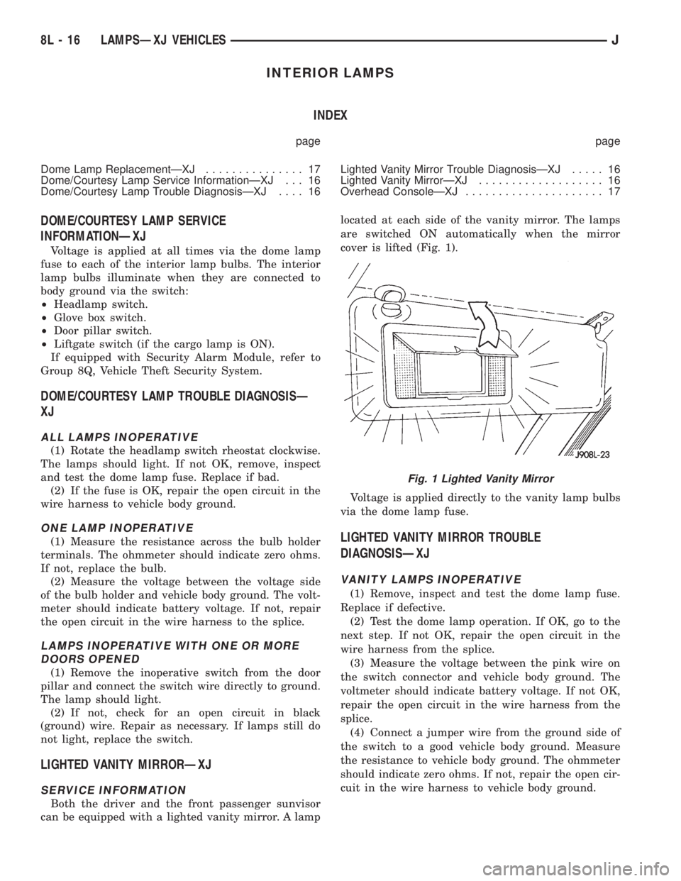
SERVICE INFORMATION
Both the driver and the front passenger sunvisor
can be equipped with a lighted vanity mirror. A lamplocated at each side of the vanity mirror. The lamps
are switched ON automatically when the mirror
cover is lifted (Fig. 1).
Voltage is applied directly to the vanity lamp bulbs
via the dome lamp fuse.
LIGHTED VANITY MIRROR TROUBLE
DIAGNOSISÐXJ
VANITY LAMPS INOPERATIVE
(1) Remove, inspect and test the dome lamp fuse.
Replace if defective.
(2) Test the dome lamp operation. If OK, go to the
next step. If not OK, repair the open circuit in the
wire harness from the splice.
(3) Measure the voltage between the pink wire on
the switch connector and vehicle body ground. The
voltmeter should indicate battery voltage. If not OK,
repair the open circuit in the wire harness from the
splice.
(4) Connect a jumper wire from the ground side of
the switch to a good vehicle body ground. Measure
the resistance to vehicle body ground. The ohmmeter
should indicate zero ohms. If not, repair the open cir-
cuit in the wire harness to vehicle body ground.
Fig. 1 Lighted Vanity Mirror
8L - 16 LAMPSÐXJ VEHICLESJ