oil dipstick JEEP CHEROKEE 1995 Service Repair Manual
[x] Cancel search | Manufacturer: JEEP, Model Year: 1995, Model line: CHEROKEE, Model: JEEP CHEROKEE 1995Pages: 2198, PDF Size: 82.83 MB
Page 17 of 2198
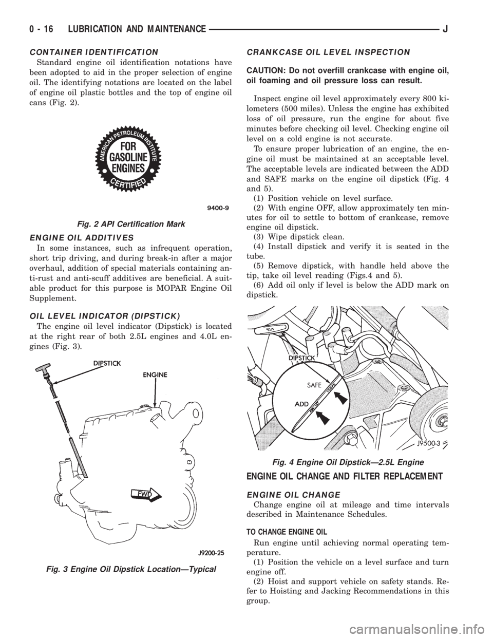
CONTAINER IDENTIFICATION
Standard engine oil identification notations have
been adopted to aid in the proper selection of engine
oil. The identifying notations are located on the label
of engine oil plastic bottles and the top of engine oil
cans (Fig. 2).
ENGINE OIL ADDITIVES
In some instances, such as infrequent operation,
short trip driving, and during break-in after a major
overhaul, addition of special materials containing an-
ti-rust and anti-scuff additives are beneficial. A suit-
able product for this purpose is MOPAR Engine Oil
Supplement.
OIL LEVEL INDICATOR (DIPSTICK)
The engine oil level indicator (Dipstick) is located
at the right rear of both 2.5L engines and 4.0L en-
gines (Fig. 3).
CRANKCASE OIL LEVEL INSPECTION
CAUTION: Do not overfill crankcase with engine oil,
oil foaming and oil pressure loss can result.
Inspect engine oil level approximately every 800 ki-
lometers (500 miles). Unless the engine has exhibited
loss of oil pressure, run the engine for about five
minutes before checking oil level. Checking engine oil
level on a cold engine is not accurate.
To ensure proper lubrication of an engine, the en-
gine oil must be maintained at an acceptable level.
The acceptable levels are indicated between the ADD
and SAFE marks on the engine oil dipstick (Fig. 4
and 5).
(1) Position vehicle on level surface.
(2) With engine OFF, allow approximately ten min-
utes for oil to settle to bottom of crankcase, remove
engine oil dipstick.
(3) Wipe dipstick clean.
(4) Install dipstick and verify it is seated in the
tube.
(5) Remove dipstick, with handle held above the
tip, take oil level reading (Figs.4 and 5).
(6) Add oil only if level is below the ADD mark on
dipstick.
ENGINE OIL CHANGE AND FILTER REPLACEMENT
ENGINE OIL CHANGE
Change engine oil at mileage and time intervals
described in Maintenance Schedules.
TO CHANGE ENGINE OIL
Run engine until achieving normal operating tem-
perature.
(1) Position the vehicle on a level surface and turn
engine off.
(2) Hoist and support vehicle on safety stands. Re-
fer to Hoisting and Jacking Recommendations in this
group.
Fig. 2 API Certification Mark
Fig. 3 Engine Oil Dipstick LocationÐTypical
Fig. 4 Engine Oil DipstickÐ2.5L Engine
0 - 16 LUBRICATION AND MAINTENANCEJ
Page 18 of 2198
(3) Remove oil fill cap.
(4) Place a suitable drain pan under crankcase
drain.
(5) Remove drain plug from crankcase and allow
oil to drain into pan. Inspect drain plug threads for
stretching or other damage. Replace drain plug and
gasket if damaged.
(6) Install drain plug in crankcase.
(7) Lower vehicle and fill crankcase with specified
type and amount of engine oil described in this sec-
tion.
(8) Install oil fill cap.
(9) Start engine and inspect for leaks.
(10) Stop engine and inspect oil level.
ENGINE OIL FILTER
FILTER SPECIFICATION
CAUTION: Do not use oil filter with metric threads.
The proper oil filter has SAE type 3/4 X 16 threads.
An oil filter with metric threads can result in oil
leaks and engine failure.
All Jeep engines are equipped with a high quality
full-flow, throw-away type oil filter. Chrysler Corpo-
ration recommends a Mopar or equivalent oil filter be
used.
OIL FILTER REMOVAL
(1) Position a drain pan under the oil filter.
(2) Using a suitable oil filter wrench loosen filter.
(3) Rotate the oil filter counterclockwise to remove
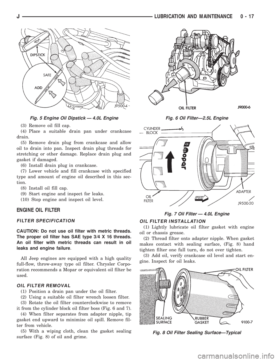
it from the cylinder block oil filter boss (Fig. 6 and 7).
(4) When filter separates from adapter nipple, tip
gasket end upward to minimize oil spill. Remove fil-
ter from vehicle.
(5) With a wiping cloth, clean the gasket sealing
surface (Fig. 8) of oil and grime.
OIL FILTER INSTALLATION
(1) Lightly lubricate oil filter gasket with engine
oil or chassis grease.
(2) Thread filter onto adapter nipple. When gasket
makes contact with sealing surface, (Fig. 8) hand
tighten filter one full turn, do not over tighten.
(3) Add oil, verify crankcase oil level and start en-
gine. Inspect for oil leaks.
Fig. 5 Engine Oil Dipstick Ð 4.0L EngineFig. 6 Oil FilterÐ2.5L Engine
Fig. 7 Oil Filter Ð 4.0L Engine
Fig. 8 Oil Filter Sealing SurfaceÐTypical
JLUBRICATION AND MAINTENANCE 0 - 17
Page 24 of 2198
If the transmission is warm, lube oil could
drip out of the fill hole. This is acceptable but
the lube oil should not gush out of the fill hole.
(2) If not acceptable, raise the lube oil level to the
bottom edge of the transmission fill hole.
Add lube oil in small amounts to raise the
level.
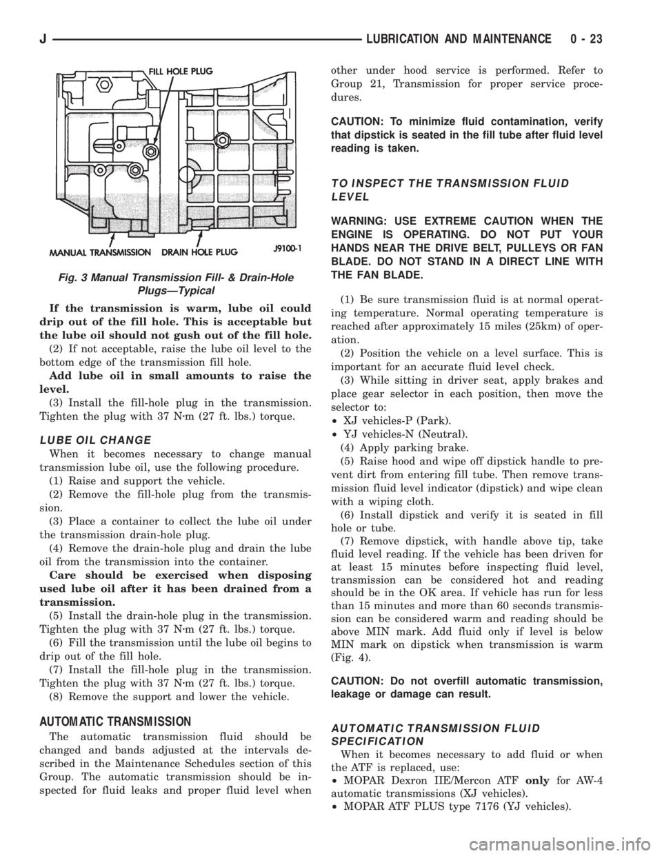
(3) Install the fill-hole plug in the transmission.
Tighten the plug with 37 Nzm (27 ft. lbs.) torque.
LUBE OIL CHANGE
When it becomes necessary to change manual
transmission lube oil, use the following procedure.
(1) Raise and support the vehicle.
(2) Remove the fill-hole plug from the transmis-
sion.
(3) Place a container to collect the lube oil under
the transmission drain-hole plug.
(4) Remove the drain-hole plug and drain the lube
oil from the transmission into the container.
Care should be exercised when disposing
used lube oil after it has been drained from a
transmission.
(5) Install the drain-hole plug in the transmission.
Tighten the plug with 37 Nzm (27 ft. lbs.) torque.
(6) Fill the transmission until the lube oil begins to
drip out of the fill hole.
(7) Install the fill-hole plug in the transmission.
Tighten the plug with 37 Nzm (27 ft. lbs.) torque.
(8) Remove the support and lower the vehicle.
AUTOMATIC TRANSMISSION
The automatic transmission fluid should be
changed and bands adjusted at the intervals de-
scribed in the Maintenance Schedules section of this
Group. The automatic transmission should be in-
spected for fluid leaks and proper fluid level whenother under hood service is performed. Refer to
Group 21, Transmission for proper service proce-
dures.
CAUTION: To minimize fluid contamination, verify
that dipstick is seated in the fill tube after fluid level
reading is taken.
TO INSPECT THE TRANSMISSION FLUID
LEVEL
WARNING: USE EXTREME CAUTION WHEN THE
ENGINE IS OPERATING. DO NOT PUT YOUR
HANDS NEAR THE DRIVE BELT, PULLEYS OR FAN
BLADE. DO NOT STAND IN A DIRECT LINE WITH
THE FAN BLADE.
(1) Be sure transmission fluid is at normal operat-
ing temperature. Normal operating temperature is
reached after approximately 15 miles (25km) of oper-
ation.
(2) Position the vehicle on a level surface. This is
important for an accurate fluid level check.
(3) While sitting in driver seat, apply brakes and
place gear selector in each position, then move the
selector to:
²XJ vehicles-P (Park).
²YJ vehicles-N (Neutral).
(4) Apply parking brake.
(5) Raise hood and wipe off dipstick handle to pre-
vent dirt from entering fill tube. Then remove trans-
mission fluid level indicator (dipstick) and wipe clean
with a wiping cloth.
(6) Install dipstick and verify it is seated in fill
hole or tube.
(7) Remove dipstick, with handle above tip, take
fluid level reading. If the vehicle has been driven for
at least 15 minutes before inspecting fluid level,
transmission can be considered hot and reading
should be in the OK area. If vehicle has run for less
than 15 minutes and more than 60 seconds transmis-
sion can be considered warm and reading should be
above MIN mark. Add fluid only if level is below
MIN mark on dipstick when transmission is warm
(Fig. 4).
CAUTION: Do not overfill automatic transmission,
leakage or damage can result.
AUTOMATIC TRANSMISSION FLUID
SPECIFICATION
When it becomes necessary to add fluid or when
the ATF is replaced, use:
²MOPAR Dexron IIE/Mercon ATFonlyfor AW-4
automatic transmissions (XJ vehicles).
²MOPAR ATF PLUS type 7176 (YJ vehicles).
Fig. 3 Manual Transmission Fill- & Drain-Hole
PlugsÐTypical
JLUBRICATION AND MAINTENANCE 0 - 23
Page 31 of 2198
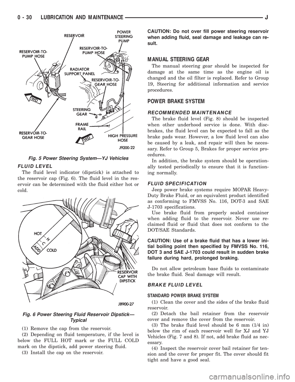
FLUID LEVEL
The fluid level indicator (dipstick) is attached to
the reservoir cap (Fig. 6). The fluid level in the res-
ervoir can be determined with the fluid either hot or
cold.
(1) Remove the cap from the reservoir.
(2) Depending on fluid temperature, if the level is
below the FULL HOT mark or the FULL COLD
mark on the dipstick, add power steering fluid.
(3) Install the cap on the reservoir.CAUTION: Do not over fill power steering reservoir
when adding fluid, seal damage and leakage can re-
sult.
MANUAL STEERING GEAR
The manual steering gear should be inspected for
damage at the same time as the engine oil is
changed and the oil filter is replaced. Refer to Group
19, Steering for additional information and service
procedures.
POWER BRAKE SYSTEM
RECOMMENDED MAINTENANCE
The brake fluid level (Fig. 8) should be inspected
when other underhood service is done. With disc-
brakes, the fluid level can be expected to fall as the
brake pads wear. However, a low fluid level can also
be caused by a leak, and repair will then be neces-
sary. Refer to Group 5, Brakes for proper service pro-
cedures.
In addition, the brake system should be operation-
ally tested periodically to ensure that it is function-
ing normally.
FLUID SPECIFICATION
Jeep power brake systems require MOPAR Heavy-
Duty Brake Fluid, or an equivalent product identified
as conforming to FMVSS No. 116, DOT-3 and SAE
J-1703 specifications.
Use brake fluid from properly sealed container
when adding fluid to the reservoir. Never use re-
claimed fluid or fluid that does not conform to the
DOT/SAE Standards.
CAUTION: Use of a brake fluid that has a lower ini-
tial boiling point then specified by FMVSS No. 116,
DOT 3 and SAE J-1703 could result in sudden brake
failure during hard, prolonged braking.
Do not allow petroleum base fluids to contaminate
the brake fluid. Seal damage will result.
BRAKE FLUID LEVEL
STANDARD POWER BRAKE SYSTEM
(1) Clean the cover and the sides of the brake fluid
reservoir.
(2) Detach the bail retainer from the reservoir
cover and remove the cover from the reservoir.
(3) The brake fluid level should be 6 mm (1/4 in)
below the rim of each reservoir well for XJ and YJ
Vehicles (Fig. 7 and 8). If not, add brake fluid as nec-
essary.
(4) Inspect the reservoir cover bail retainer for ten-
sion and the cover for proper fit. The cover should fit
tight and have a good seal.
Fig. 5 Power Steering SystemÐYJ Vehicles
Fig. 6 Power Steering Fluid Reservoir DipstickÐ
Typical
0 - 30 LUBRICATION AND MAINTENANCEJ
Page 248 of 2198
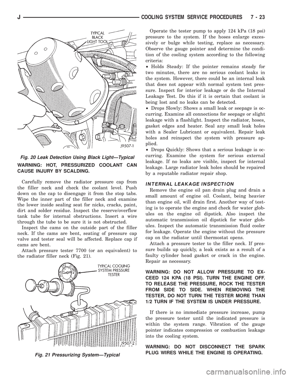
WARNING: HOT, PRESSURIZED COOLANT CAN
CAUSE INJURY BY SCALDING.
Carefully remove the radiator pressure cap from
the filler neck and check the coolant level. Push
down on the cap to disengage it from the stop tabs.
Wipe the inner part of the filler neck and examine
the lower inside sealing seat for nicks, cracks, paint,
dirt and solder residue. Inspect the reserve/overflow
tank tube for internal obstructions. Insert a wire
through the tube to be sure it is not obstructed.
Inspect the cams on the outside part of the filler
neck. If the cams are bent, seating of pressure cap
valve and tester seal will be affected. Replace cap if
cams are bent.
Attach pressure tester 7700 (or an equivalent) to
the radiator filler neck (Fig. 21).Operate the tester pump to apply 124 kPa (18 psi)
pressure to the system. If the hoses enlarge exces-
sively or bulge while testing, replace as necessary.
Observe the gauge pointer and determine the condi-
tion of the cooling system according to the following
criteria:
²Holds Steady: If the pointer remains steady for
two minutes, there are no serious coolant leaks in
the system. However, there could be an internal leak
that does not appear with normal system test pres-
sure. Inspect for interior leakage or do the Internal
Leakage Test. Do this if it is certain that coolant is
being lost and no leaks can be detected.
²Drops Slowly: Shows a small leak or seepage is oc-
curring. Examine all connections for seepage or slight
leakage with a flashlight. Inspect the radiator, hoses,
gasket edges and heater. Seal any small leak holes
with a Sealer Lubricant or equivalent. Repair leak
holes and reinspect the system with pressure ap-
plied.
²Drops Quickly: Shows that a serious leakage is oc-
curring. Examine the system for serious external
leakage. If no leaks are visible, inspect for internal
leakage. Large radiator leak holes should be repaired
by a reputable radiator repair shop.
INTERNAL LEAKAGE INSPECTION
Remove the engine oil pan drain plug and drain a
small amount of engine oil. Coolant, being heavier
than engine oil, will drain first. Another way of test-
ing is to operate the engine and check for water glob-
ules on the engine oil dipstick. Also inspect the
automatic transmission oil dipstick for water glob-
ules. Inspect the automatic transmission fluid cooler
for leakage. Operate the engine without the pressure
cap on the radiator until thermostat opens.
Attach a pressure tester to the filler neck. If pres-
sure builds up quickly, a leak exists as a result of a
faulty cylinder head gasket or crack in the engine.
Repair as necessary.
WARNING: DO NOT ALLOW PRESSURE TO EX-
CEED 124 KPA (18 PSI). TURN THE ENGINE OFF.
TO RELEASE THE PRESSURE, ROCK THE TESTER
FROM SIDE TO SIDE. WHEN REMOVING THE
TESTER, DO NOT TURN THE TESTER MORE THAN
1/2 TURN IF THE SYSTEM IS UNDER PRESSURE.
If there is no immediate pressure increase, pump
the pressure tester until the indicated pressure is
within the system range. Vibration of the gauge
pointer indicates compression or combustion leakage
into the cooling system.
WARNING: DO NOT DISCONNECT THE SPARK
PLUG WIRES WHILE THE ENGINE IS OPERATING.
Fig. 20 Leak Detection Using Black LightÐTypical
Fig. 21 Pressurizing SystemÐTypical
JCOOLING SYSTEM SERVICE PROCEDURES 7 - 23
Page 1097 of 2198
CYLINDER COMBUSTION PRESSURE LEAKAGE
TEST
The combustion pressure leakage test provides an
accurate means for determining engine condition.
Combustion pressure leakage testing will detect:
²Exhaust and intake valve leaks (improper seat-
ing).
²Leaks between adjacent cylinders or into water
jacket.
²Any causes for combustion/compression pressure
loss.
WARNING: DO NOT REMOVE THE RADIATOR CAP
WITH THE SYSTEM HOT AND UNDER PRESSURE
BECAUSE SERIOUS BURNS FROM COOLANT CAN
OCCUR.
Check the coolant level and fill as required. DO
NOT install the radiator cap.
Start and operate the engine until it attains nor-
mal operating temperature, then turn the engine
OFF.
Remove the spark plugs.
Remove the oil filler cap.
Remove the air cleaner.
Calibrate the tester according to the manufactur-
er's instructions. The shop air source for testing
should maintain 483 kPa (70 psi) minimum, 1 379
kPa (200 psi) maximum and 552 kPa (80 psi) recom-
mended.
Perform the test procedures on each cylinder ac-
cording to the tester manufacturer's instructions.
While testing, listen for pressurized air escaping
through the throttle body, tailpipe and oil filler cap
opening. Check for bubbles in the radiator coolant.
All gauge pressure indications should be equal,
with no more than 25% leakage.
FOR EXAMPLE:At 552 kPa (80 psi) input pres-
sure, a minimum of 414 kPa (60 psi) should be main-
tained in the cylinder.
Refer to the Cylinder Combustion Pressure Leak-
age Test Diagnosis chart.
INSPECTION (ENGINE OIL LEAKS IN GENERAL)
Begin with a through visual inspection of the en-
gine, particularly at the area of the suspected leak. If
an oil leak source is not readily identifiable, the fol-
lowing steps should be followed:
(1) Do not clean or degrease the engine at this
time because some solvents may cause rubber to
swell, temporarily stopping the leak.
(2) Add an oil soluble dye (use as recommended by
manufacturer). Start the engine and let idle for ap-
proximately 15 minutes. Check the oil dipstick to
make sure the dye is thoroughly mixed as indicated
with a bright yellow color under a black light.(3) Using a black light, inspect the entire engine
for fluorescent dye, particularly at the suspected area
of oil leak. If the oil leak is found and identified, re-
pair per service manual instructions.
(4) If dye is not observed, drive the vehicle at var-
ious speeds for approximately 24km (15 miles), and
repeat step (3).
If the oil leak source is not positively identi-
fied at this time, proceed with the air leak detec-
tion test method as follows:
(1) Disconnect the breather cap to air cleaner hose
at the breather cap end. Cap or plug breather cap
nipple.
(2) Remove the PCV valve from the cylinder head
cover. Cap or plug the PCV valve grommet.
(3) Attach an air hose with pressure gauge and
regulator to the dipstick tube.
CAUTION: Do not subject the engine assembly to
more than 20.6 kpa (3 PSI) of test pressure.
(4) Gradually apply air pressure from 1 psi to 2.5
psi maximum while applying soapy water at the sus-
pected source. Adjust the regulator to the suitable
test pressure that provide the best bubbles which
will pinpoint the leak source. If the oil leak is de-
tected and identified, repair per service manual pro-
cedures.
(5) If the leakage occurs at the rear oil seal area,
refer to the section, Inspection for Rear Seal Area
Leak.
(6) If no leaks are detected, turn off the air supply
and remove the air hose and all plugs and caps. In-
stall the PCV valve and breather cap hose. Proceed
to step 7.
(7) Clean the oil off the suspect oil leak area using
a suitable solvent. Drive the vehicle at various
speeds approximately 24 km (15 miles). Inspect the
engine for signs of an oil leak by using a black light.
INSPECTION FOR REAR SEAL AREA LEAKS
Since it is sometimes difficult to determine the
source of an oil leak in the rear seal area of the en-
gine, a more involved inspection is necessary. The fol-
lowing steps should be followed to help pinpoint the
source of the leak.
If the leakage occurs at the crankshaft rear oil seal
area:
(1) Disconnect the battery.
(2) Raise the vehicle.
(3) Remove torque converter or clutch housing
cover and inspect rear of block for evidence of oil.
Use a black light to check for the oil leak:
(a) Circular spray pattern generally indicates
seal leakage or crankshaft damage.
(b) Where leakage tends to run straight down,
possible causes are a porous block, distributor seal,
camshaft bore cup plugs oil galley pipe plugs, oil
9 - 6 ENGINESJ
Page 1140 of 2198
(13) Install the drain plug. Tighten the plug to 34
Nzm (25 ft. lbs.) torque.
(14) Lower the vehicle.
(15) Install the spark plugs. Tighten the plugs to
37 Nzm (27 ft. lbs.) torque.
(16) Fill the oil pan with engine oil to the full
mark on the dipstick level.
(17) Connect negative cable to battery.
REAR MAIN OIL SEALS
REMOVAL
(1) Remove the flywheel or converter drive plate.
Discard the old bolts.
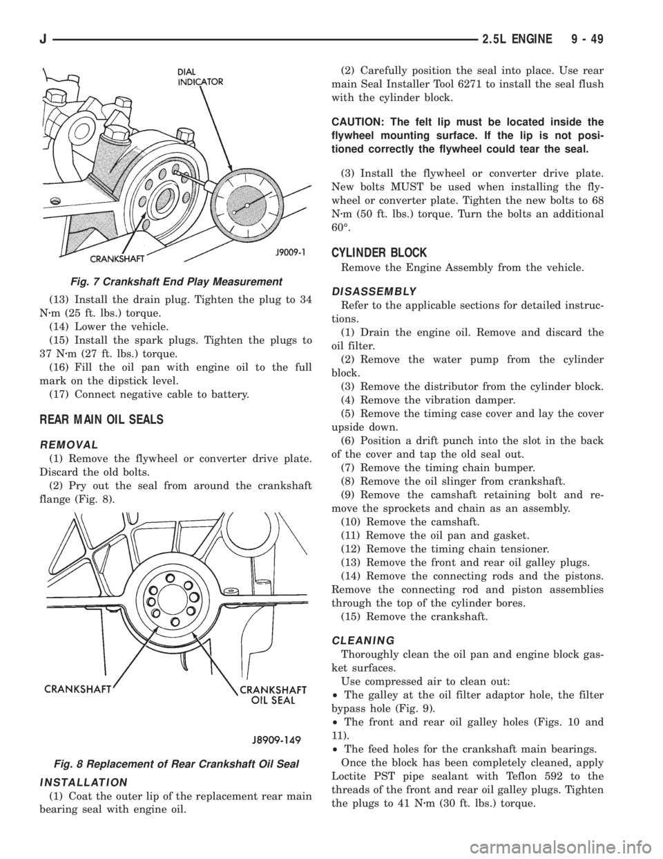
(2) Pry out the seal from around the crankshaft
flange (Fig. 8).
INSTALLATION
(1) Coat the outer lip of the replacement rear main
bearing seal with engine oil.(2) Carefully position the seal into place. Use rear
main Seal Installer Tool 6271 to install the seal flush
with the cylinder block.
CAUTION: The felt lip must be located inside the
flywheel mounting surface. If the lip is not posi-
tioned correctly the flywheel could tear the seal.
(3) Install the flywheel or converter drive plate.
New bolts MUST be used when installing the fly-
wheel or converter plate. Tighten the new bolts to 68
Nzm (50 ft. lbs.) torque. Turn the bolts an additional
60É.
CYLINDER BLOCK
Remove the Engine Assembly from the vehicle.
DISASSEMBLY
Refer to the applicable sections for detailed instruc-
tions.
(1) Drain the engine oil. Remove and discard the
oil filter.
(2) Remove the water pump from the cylinder
block.
(3) Remove the distributor from the cylinder block.
(4) Remove the vibration damper.
(5) Remove the timing case cover and lay the cover
upside down.
(6) Position a drift punch into the slot in the back
of the cover and tap the old seal out.
(7) Remove the timing chain bumper.
(8) Remove the oil slinger from crankshaft.
(9) Remove the camshaft retaining bolt and re-
move the sprockets and chain as an assembly.
(10) Remove the camshaft.
(11) Remove the oil pan and gasket.
(12) Remove the timing chain tensioner.
(13) Remove the front and rear oil galley plugs.
(14) Remove the connecting rods and the pistons.
Remove the connecting rod and piston assemblies
through the top of the cylinder bores.
(15) Remove the crankshaft.
CLEANING
Thoroughly clean the oil pan and engine block gas-
ket surfaces.
Use compressed air to clean out:
²The galley at the oil filter adaptor hole, the filter
bypass hole (Fig. 9).
²The front and rear oil galley holes (Figs. 10 and
11).
²The feed holes for the crankshaft main bearings.
Once the block has been completely cleaned, apply
Loctite PST pipe sealant with Teflon 592 to the
threads of the front and rear oil galley plugs. Tighten
the plugs to 41 Nzm (30 ft. lbs.) torque.
Fig. 7 Crankshaft End Play Measurement
Fig. 8 Replacement of Rear Crankshaft Oil Seal
J2.5L ENGINE 9 - 49
Page 1180 of 2198
If the clearance exceeds specification using a pair
of 0.051 mm (0.002 inch) undersize bearing inserts,
measure crankshaft journal diameter with a mi-
crometer. If the journal diameter is correct, the
crankshaft bore in the cylinder block may be mis-
aligned, which requires cylinder block replacement or
machining to true bore.
Replace the crankshaft or grind to accept the ap-
propriate undersize bearing inserts if:
²Journal diameters 1 through 6 are less than
63.4517 mm (2.4981 inches)
²Journal 7 diameter is less than 63.4365 mm
(2.4975 inches).
Once the proper clearances have been obtained,
proceed to Crankshaft Main BearingÐInstallation.
MAIN BEARING JOURNAL DIAMETER (CRANKSHAFT
REMOVED)
Remove the crankshaft from the cylinder block (re-
fer to Cylinder Block - Disassemble).
Clean the oil off the main bearing journal.
Determine the maximum diameter of the journal
with a micrometer. Measure at two locations 90É
apart at each end of the journal.
The maximum allowable taper and out of round is
0.013 mm (0.0005 inch). Compare the measured di-
ameter with the journal diameter specification (Main
Bearing Fitting Chart). Select inserts required to ob-
tain the specified bearing-to-journal clearance.
Install the crankshaft into the cylinder block (refer
to Cylinder Block - Assemble and Crankshaft Main
Bearings - Installation).
INSTALLATION
(1) Lubricate the bearing surface of each insert
with engine oil.
(2) Loosen all the main bearing caps. Install the
main bearing upper inserts.
(3) Install the lower bearing inserts into the main
bearing caps.
(4) Install the main bearing cap(s) and lower in-
sert(s).
(5) Tighten the bolts of caps 1, 2, 4, 5, 6, and 7 to
54 Nzm (40 ft. lbs.) torque. Now tighten these bolts to
95 Nzm (70 ft. lbs.) torque. Finally, tighten these
bolts to 108 Nzm (80 ft. lbs.) torque.
(6) Push the crankshaft forward and backward.
Load the crankshaft front or rear and tighten cap
bolt No.3 to 54 Nzm (40 ft. lbs.) torque. Then tighten
to 95 Nzm (70 ft. lbs.) torque and finally tighten to
108 Nzm (80 ft. lbs.) torque.
(7) Rotate the crankshaft after tightening each
main bearing cap to ensure the crankshaft rotates
freely.
(8) Check crankshaft end play. Crankshaft end
play is controlled by the thrust bearing which is
flange and installed at the No.2 main bearing posi-
tion.(a) Attach a magnetic base dial indicator to the
cylinder block at either the front or rear of the en-
gine.
(b) Position the dial indicator rod so that it is
parallel to the center line of the crankshaft.
(c) Pry the crankshaft forward, position the dial
indicator to zero.
(d) Pry the crankshaft forward and backward.
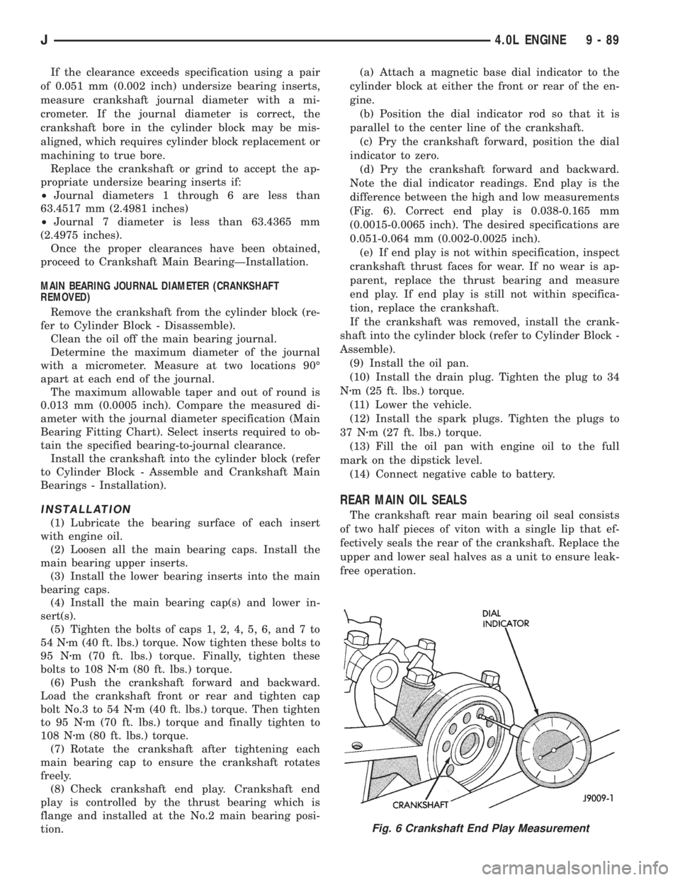
Note the dial indicator readings. End play is the
difference between the high and low measurements
(Fig. 6). Correct end play is 0.038-0.165 mm
(0.0015-0.0065 inch). The desired specifications are
0.051-0.064 mm (0.002-0.0025 inch).
(e) If end play is not within specification, inspect
crankshaft thrust faces for wear. If no wear is ap-
parent, replace the thrust bearing and measure
end play. If end play is still not within specifica-
tion, replace the crankshaft.
If the crankshaft was removed, install the crank-
shaft into the cylinder block (refer to Cylinder Block -
Assemble).
(9) Install the oil pan.
(10) Install the drain plug. Tighten the plug to 34
Nzm (25 ft. lbs.) torque.
(11) Lower the vehicle.
(12) Install the spark plugs. Tighten the plugs to
37 Nzm (27 ft. lbs.) torque.
(13) Fill the oil pan with engine oil to the full
mark on the dipstick level.
(14) Connect negative cable to battery.
REAR MAIN OIL SEALS
The crankshaft rear main bearing oil seal consists
of two half pieces of viton with a single lip that ef-
fectively seals the rear of the crankshaft. Replace the
upper and lower seal halves as a unit to ensure leak-
free operation.
Fig. 6 Crankshaft End Play Measurement
J4.0L ENGINE 9 - 89
Page 1476 of 2198
30RH/32RH IN-VEHICLE SERVICE
INDEX
page page
Converter Drainback Check Valve Service...... 113
Fluid and Filter Replacement................. 99
Fluid Level Check......................... 99
Front Band Adjustment.................... 102
Governor and Park Gear Service............. 105
Oil Filter Replacement..................... 103
Park Interlock Cable Adjustment (XJ).......... 101
Park Lock Component Replacement.......... 108
Park/Neutral Position Switch Service.......... 109
Rear Band Adjustment.................... 103
Recommended Fluid....................... 99Refilling After Overhaul or Fluid/Filter Change . . . 100
Shift Cable Adjustment (XJ)................. 100
Shift Linkage Adjustment (YJ)............... 100
Speedometer Service..................... 109
Throttle Valve Cable Adjustment (XJ/YJ)....... 101
Transmission Cooler Flow Testing............ 113
Transmission Cooler Line and Fitting Service.... 111
Transmission Cooler Reverse Flushing......... 114
Valve Body Installation.................... 104
Valve Body Removal...................... 104
Valve Body Service....................... 104
RECOMMENDED FLUID
Recommended (and preferred) fluid for 30RH/32RH
transmissions is Mopar ATF Plus, type 7176.
Dexron II is not really recommended and should
only be used when ATF Plus is not available.
FLUID LEVEL CHECK
Transmission fluid level should be checked monthly
under normal operation. If the vehicle is used for
trailer towing or similar heavy load hauling, check
fluid level and condition weekly.
Fluid level is checked with the engine running at
curb idle speed, the transmission in Neutral and the
transmission fluid at normal operating temperature.
FLUID LEVEL CHECK PROCEDURE
(1) Transmission fluid must be at normal operating
temperature for accurate fluid level check. Drive ve-
hicle if necessary to bring fluid temperature up to
normal hot operating temperature of 82ÉC (180ÉF).
(2) Position vehicle on level surface. This is ex-
tremely important for accurate fluid level check.
(3) Start and run engine at curb idle speed.
(4) Apply parking brakes.
(5) Shift transmission momentarily into all gear
ranges. Then shift transmission back to Neutral.
(6) Clean top of filler tube and dipstick to keep dirt
from entering tube.
(7) Remove dipstick and check fluid level as fol-
lows:
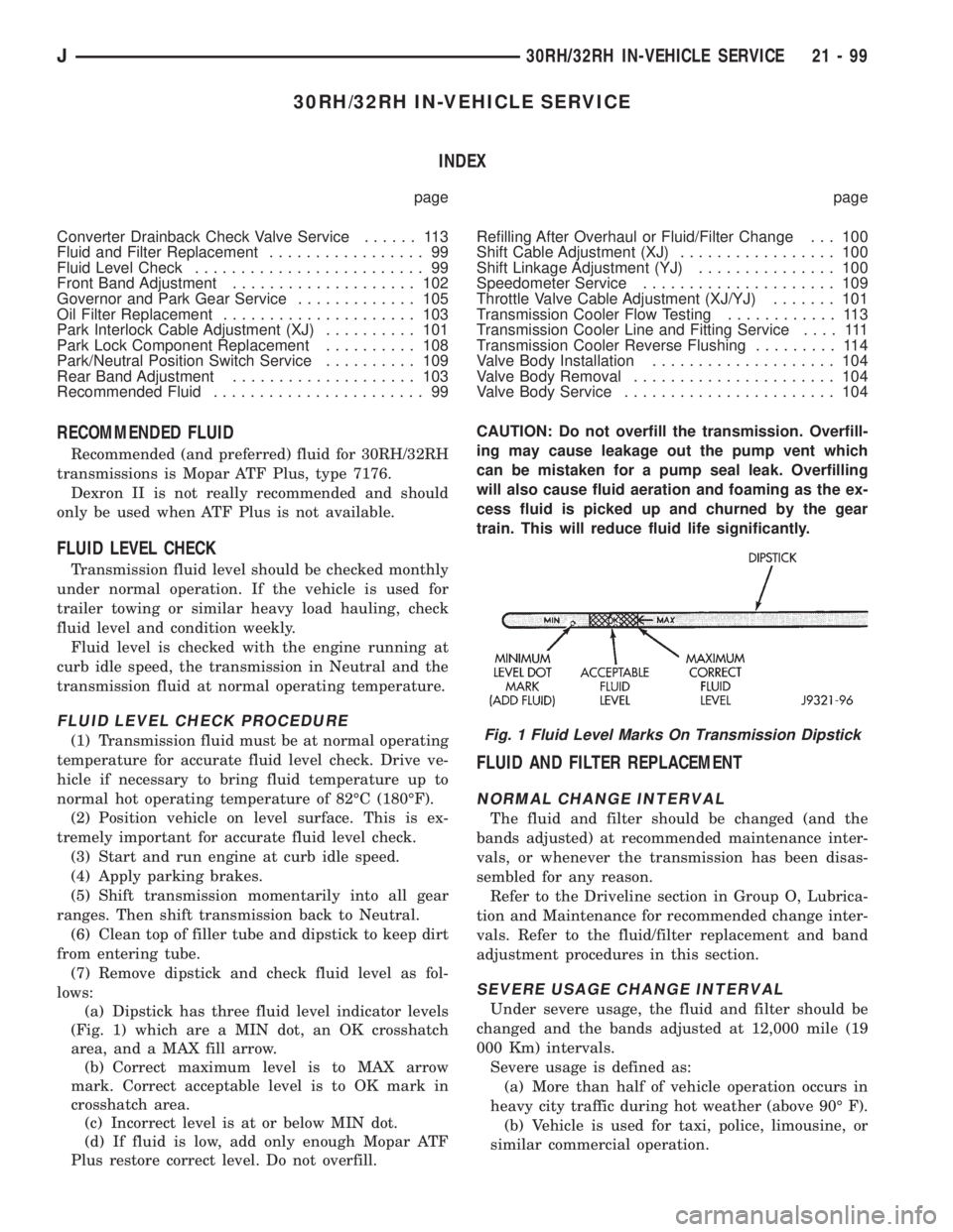
(a) Dipstick has three fluid level indicator levels
(Fig. 1) which are a MIN dot, an OK crosshatch
area, and a MAX fill arrow.
(b) Correct maximum level is to MAX arrow
mark. Correct acceptable level is to OK mark in
crosshatch area.
(c) Incorrect level is at or below MIN dot.
(d) If fluid is low, add only enough Mopar ATF
Plus restore correct level. Do not overfill.CAUTION: Do not overfill the transmission. Overfill-
ing may cause leakage out the pump vent which
can be mistaken for a pump seal leak. Overfilling
will also cause fluid aeration and foaming as the ex-
cess fluid is picked up and churned by the gear
train. This will reduce fluid life significantly.
FLUID AND FILTER REPLACEMENT
NORMAL CHANGE INTERVAL
The fluid and filter should be changed (and the
bands adjusted) at recommended maintenance inter-
vals, or whenever the transmission has been disas-
sembled for any reason.
Refer to the Driveline section in Group O, Lubrica-
tion and Maintenance for recommended change inter-
vals. Refer to the fluid/filter replacement and band
adjustment procedures in this section.
SEVERE USAGE CHANGE INTERVAL
Under severe usage, the fluid and filter should be
changed and the bands adjusted at 12,000 mile (19
000 Km) intervals.
Severe usage is defined as:
(a) More than half of vehicle operation occurs in
heavy city traffic during hot weather (above 90É F).
(b) Vehicle is used for taxi, police, limousine, or
similar commercial operation.
Fig. 1 Fluid Level Marks On Transmission Dipstick
J30RH/32RH IN-VEHICLE SERVICE 21 - 99
Page 1477 of 2198
(c) Vehicle is used for trailer towing or heavy
load hauling.
FLUID/FILTER REPLACEMENT PROCEDURE
(1) Raise vehicle.
(2) Remove oil pan and drain fluid.
(3) Clean oil pan and pan magnet. Then clean re-
maining gasket material from gasket surface of
transmission case.
(4) Remove fluid filter screws and remove filter.
(5) Position new filter on valve body and install fil-
ter screws. Tighten screws to 4 Nzm (35 in. lbs.)
torque.
(6) Adjust rear band at this time if required.
(7) Position new gasket on oil pan and install pan
on transmission. Tighten pan bolts to 150 in. lbs. (17
Nzm) torque.
(8) Adjust front band at this time if required.
(9) Lower vehicle and refill transmission with Mo-
par ATF Plus, type 7176 fluid.
REFILLING AFTER OVERHAUL OR FLUID/FILTER
CHANGE
The most effective way to avoid overfilling after a
fluid change or overhaul is as follows:
(1) Remove dipstick and insert clean funnel in
transmission fill tube.
(2) Add following initial quantity of Mopar ATF
Plus to transmission:
(a) If only fluid and filter were changed, add3
pints (1-1/2 quarts)of ATF Plus to transmission.
(b) If transmission was completely overhauled
and torque converter was replaced or drained, add
10 pints (5 quarts)of ATF Plus to transmission.
(3) Apply parking brakes.
(4) Start and run engine at normal curb idle speed.
(5) Apply service brakes, shift transmission
through all gear ranges then back to Neutral, and
leave engine running at curb idle speed.
(6) Remove funnel, insert dipstick and check fluid
level. Add only enough fluid to bring level toMIN
dot mark on dipstick.
(7) Drive vehicle until transmission fluid is at nor-
mal operating temperature. Then recheck fluid level
as described in next step.
(8) Leave engine running at curb idle speed, shift
into Neutral, and check fluid level again. This time,
add just enough fluid to bring level up toMAX ar-
row mark but do not overfill.
(9) When fluid level is correct, shut engine off, re-
lease park brake, remove funnel, and reseat dipstick
in fill tube.
SHIFT LINKAGE ADJUSTMENT (YJ)
(1) Check linkage adjustment by starting engine in
Park and Neutral.(2) Adjustment is OK if engine starts only in park
and Neutral. Adjustment is incorrect if engine starts
in one but not both positions.
(3) If engine starts in any position other than Park
or Neutral, or if engine will not start at all, park/
neutral position switch may be faulty.
(4) Shift transmission into Park.
(5) Raise vehicle.
(6) Check condition of shift rods, bellcrank,
bellcrank brackets and linkage bushings/grommets
(Fig. 2). Tighten, repair, replace worn, damaged
parts. Do not attempt adjustment if linkage compo-
nents are worn or damaged.
(7) Loosen shift rod trunnion lock bolt or nut. Be
sure upper shift rod slides freely in trunnion (Fig. 2).
Also be sure shift rods and bellcrank rotate freely
and do not bind at any point.
(8) Verify that manual lever is in Park detent (Fig.
2). Move lever all the way rearward to be sure it is in
Park.
(9) Check for positive engagement of park lock by
attempting to rotate propeller shaft. Shaft will not
turn when park pawl is engaged.
(10) Adjust shift rod trunnion to a obtain free pin
fit in bellcrank arm and tighten trunnion lock bolt or
nut. Prevent shift rod from turning while tightening
bolt or nut. Gearshift linkage lash must be elimi-
nated to obtain proper adjustment. Eliminate lash by
pulling downward on shift rod and pressing upward
on bellcrank.
(11) Confirm proper adjustment by starting engine
in Park and Neutral. Engine should start in these
positions only.If engine starts in any position
other than Park or Neutral, adjustment is in-
correct or neutral switch is faulty.
(12) Lower vehicle and verify that steering lock op-
erates correctly.
SHIFT CABLE ADJUSTMENT (XJ)
(1) Shift transmission into Park.
(2) Raise vehicle.
(3) Release cable adjuster clamp to unlock cable
(Figs. 3 and 4). Clamp is at transmission end of ca-
ble.
(4) Unsnap cable from transmission cable bracket.
(5) Move transmission shift lever fully rearward to
Park detent. Lever is on manual valve shaft at driver
side of case.
(6) Verify positive engagement of park lock by at-
tempting to rotate propeller shaft. Shaft will not ro-
tate when park lock is engaged.
(7) Snap cable into cable bracket.
(8) Lock shift cable by pressing cable adjuster
clamp down until it snaps into place.
(9) Check engine starting. Engine should start only
in Park and Neutral.
(10) Lower vehicle.
21 - 100 30RH/32RH IN-VEHICLE SERVICEJ