phone JEEP CHEROKEE 1995 Service Repair Manual
[x] Cancel search | Manufacturer: JEEP, Model Year: 1995, Model line: CHEROKEE, Model: JEEP CHEROKEE 1995Pages: 2198, PDF Size: 82.83 MB
Page 1130 of 2198

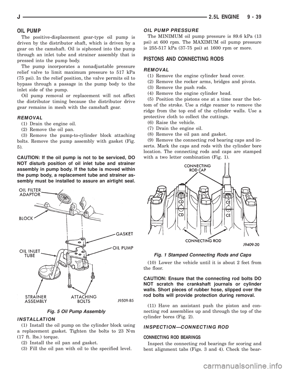
OIL PUMP
The positive-displacement gear-type oil pump is
driven by the distributor shaft, which is driven by a
gear on the camshaft. Oil is siphoned into the pump
through an inlet tube and strainer assembly that is
pressed into the pump body.
The pump incorporates a nonadjustable pressure
relief valve to limit maximum pressure to 517 kPa
(75 psi). In the relief position, the valve permits oil to
bypass through a passage in the pump body to the
inlet side of the pump.
Oil pump removal or replacement will not affect
the distributor timing because the distributor drive
gear remains in mesh with the camshaft gear.
REMOVAL
(1) Drain the engine oil.
(2) Remove the oil pan.
(3) Remove the pump-to-cylinder block attaching
bolts. Remove the pump assembly with gasket (Fig.
5).
CAUTION: If the oil pump is not to be serviced, DO
NOT disturb position of oil inlet tube and strainer
assembly in pump body. If the tube is moved within
the pump body, a replacement tube and strainer as-
sembly must be installed to assure an airtight seal.
INSTALLATION
(1) Install the oil pump on the cylinder block using
a replacement gasket. Tighten the bolts to 23 Nzm
(17 ft. lbs.) torque.
(2) Install the oil pan and gasket.
(3) Fill the oil pan with oil to the specified level.
OIL PUMP PRESSURE
The MINIMUM oil pump pressure is 89.6 kPa (13
psi) at 600 rpm. The MAXIMUM oil pump pressure
is 255-517 kPa (37-75 psi) at 1600 rpm or more.
PISTONS AND CONNECTING RODS
REMOVAL
(1) Remove the engine cylinder head cover.
(2) Remove the rocker arms, bridges and pivots.
(3) Remove the push rods.
(4) Remove the engine cylinder head.
(5) Position the pistons one at a time near the bot-
tom of the stroke. Use a ridge reamer to remove the
ridge from the top end of the cylinder walls. Use a
protective cloth to collect the cuttings.
(6) Raise the vehicle.
(7) Drain the engine oil.
(8) Remove the oil pan and gasket.
(9) Remove the connecting rod bearing caps and in-
serts. Mark the caps and rods with the cylinder bore
location. The connecting rods and caps are stamped
with a two letter combination (Fig. 1).
(10) Lower the vehicle until it is about 2 feet from
the floor.
CAUTION: Ensure that the connecting rod bolts DO
NOT scratch the crankshaft journals or cylinder
walls. Short pieces of rubber hose, slipped over the
rod bolts will provide protection during removal.
(11) Have an assistant push the piston and con-
necting rod assemblies up and through the top of the
cylinder bores (Fig. 2).
INSPECTIONÐCONNECTING ROD
CONNECTING ROD BEARINGS
Inspect the connecting rod bearings for scoring and
bent alignment tabs (Figs. 3 and 4). Check the bear-
Fig. 5 Oil Pump Assembly
Fig. 1 Stamped Connecting Rods and Caps
J2.5L ENGINE 9 - 39
Page 2186 of 2198

UNITED STATES
The special service tools referred to herein are required for certain service operations. These special service tools
or their equivalent, if not obtainable through a local source, are available through the following outlet.
28635 Mound Road, Warren, Michigan 48092, U.S.A.
MILLER SPECIAL TOOLS
OTC Division, SPX Corporation
Telephone 1-800-801-5420 FAX 1-800-578-7375
CANADA
The special service tools referred to herein are required for certain service operations. These special service tools
or their equivalent, if not obtainable through a local source, are available through the following outlet.
C & D Riley Enterprises Ltd., P.O. Box 243, Amherstburg, Ontario N9V 2Z4
Telephone (519) 736-4600 FAX (519) 736-8433
INTERNATIONAL
The special service tools referred to herein are required for certain service operations. These special service tools
or their equivalent, if not obtainable through a local source, are available through the following outlet.
28635 Mound Road, Warren, Michigan 48092, U.S.A.
MILLER SPECIAL TOOLS
OTC Division, SPX Corporation
Telephone 1-800-801-5420 FAX 1-800-578-7375
NEXT PAGE©
Page 2187 of 2198

CAUTION
ALL SERVICE AND REBUILDING INSTRUCTIONS CONTAINED HEREIN
ARE APPLICABLE TO, AND FOR THE CONVENIENCE OF, THE AUTOMOTIVE
TRADE ONLY. All test and repair procedures on components or assemblies in
non-automotive applications should be repaired in accordance with instructions
supplied by the manufacturer of the total product.
Proper service and repair is important to the safe, reliable, operation of all motor
vehicles. The service procedures recommended and described in this publication were
developed for professional service personnel and are effective methods for performing
vehicle repair. Following these procedures will help assure efficient economical vehicle
performance and service reliability. Some of these service procedures require the use
of special tools designed for specific procedures. These special tools should be used
when recommended throughout this publication.
Special attention should be exercised when working with spring or tension loaded
fasteners and devices such as E-Clips, Circlips, Snap rings, etc., as careless removal
may cause personal injury. Always wear safety goggles whenever working on vehicles
or vehicle components.
It is important to note that this publication contains variousCautionsandWarnings.
These should be carefully read in order to minimize the risk of personal injury, or the
possibility that improper service methods may damage the vehicle or render it unsafe.
It is important to note that theseCautionsandWarningscover only the situations
and procedures DaimlerChrysler Corporation has encountered and recommended.
DaimlerChrysler Corporation could not possibly know, evaluate, and advise the
service trade of all conceivable ways that service may be performed, or of the possible
hazards of each. Consequently, DaimlerChrysler Corporation has not undertaken any
such broad service review. Accordingly, anyone who uses a service procedure, or tool,
that is not recommended in this publication must assure oneself thoroughly that
neither personal safety, nor vehicle safety, be jeopardized by the service methods they
select.
SERVICE AND OWNER MANUALS
Available for Chrysler, Plymouth, Dodge,
Dodge Truck, and Jeep
Tvehicles.
Telephone orders may be placed at the number below.
Credit cards are accepted (no CODs). Please have your
order information available at time of call.
CALL: (800) 890-4038 OR FAX: (440) 572-0815
FOR A FREE CATALOG OR TO PLACE AN ORDER.
NEXT PAGE©
llllllllllll