power steering fluid JEEP CHEROKEE 1995 Service Repair Manual
[x] Cancel search | Manufacturer: JEEP, Model Year: 1995, Model line: CHEROKEE, Model: JEEP CHEROKEE 1995Pages: 2198, PDF Size: 82.83 MB
Page 5 of 2198
MAINTENANCE SCHEDULES
INTRODUCTION
There are two maintenance schedules that show
proper service intervals for Jeep Cherokee and Jeep
Wrangler vehicles. Use the schedule that best de-
scribes the conditions the vehicle is operated under.
When mileage and time is listed, follow the interval
that occurs first.
ScheduleÐAlists all the scheduled maintenance
to be performed under normal operating conditions.
ScheduleÐBis a schedule for vehicles that are
usually operated under one or more of the following
conditions.
²Frequent short trip driving less than 5 miles (8
km).
²Frequent driving in dusty conditions.
²Trailer towing or heavy load hauling.
²Frequent long periods of engine idling.
²Sustained high speed operation.
²Desert operation.
²Frequent starting and stopping.
²Cold climate operation.
²Off road driving.
²Commercial service.
²Snow plow operation.
²More than half of vehicle operation occurs in
heavy city traffic during hot weather (above 90É F).
AT EACH STOP FOR GASOLINE
²Check engine oil level and add as required.
²Check windshield washer solvent and add as re-
quired.
ONCE A MONTH
²Check tire pressure and look for unusual tire wear
or damage.
²Check fluid levels of coolant reservoir, brake mas-
ter cylinder, power steering and transmission. Add
fluid as required.
²Check all lights and other electrical items for cor-
rect operation.
²Inspect battery and clean and tighten terminals as
required.
²Check rubber seals on each side of the radiator for
proper fit.
AT EACH OIL CHANGE
²Inspect exhaust system.
²Inspect brake hoses.
²Rotate the tires at each oil change interval shown
on ScheduleÐA: (7,500 Miles) or every other interval
shown on ScheduleÐB: (6,000 Miles).
²Check engine coolant level, hoses, and clamps.
²Lubricate 4x4 steering linkage.
²Lubricate propeller shaft universal joints and slip
spline, if equipped.After completion of off-road (4WD) operation, the
underside of the vehicle should be thoroughly in-
spected. Examine threaded fasteners for looseness.
HARSH SURFACE ENVIRONMENTS
After vehicle operation in a harsh surface environ-
ment, the following components should be inspected
and cleaned as soon as possible:
²Brake drums.
²Brake linings.
²Front wheel bearings (2WD vehicles only).
²Axle coupling joints.
This will prevent wear and/or unpredictable brake
action.
EMISSION CONTROL SYSTEM MAINTENANCE
The schedule emission maintenance listed inbold
typeon the following schedules, must be done at the
mileage specified to assure the continued proper
functioning of the emission control system. These,
and all other maintenance services included in this
manual, should be done to provide the best vehicle
performance and reliability. More frequent mainte-
nance may be needed for vehicles in severe operating
conditions such as dusty areas and very short trip
driving.
SCHEDULEÐA
7,500 MILES (12 000 KM) OR AT 6 MONTHS
²Change engine oil.
²Replace engine oil filter.
²Lubricate steering linkage (4x4).
15,000 MILES (24 000 KM) OR AT 12 MONTHS
²Change engine oil.
²Replace engine oil filter.
²Lubricate steering linkage.
22,500 MILES (36 000 KM) OR AT 18 MONTHS
²Change engine oil.
²Replace engine oil filter.
²Lubricate steering linkage (4x4).
²Inspect brake linings.
30,000 MILES (48 000 KM) OR AT 24 MONTHS
²Replace air cleaner element.
²Replace spark plugs.
²Adjust belt tension on non-automatic tensioning
drive belts.
²Change engine oil.
²Replace engine oil filter.
²Lubricate steering linkage.
²Drain and refill automatic transmission.
²Drain and refill transfer case.
0 - 4 LUBRICATION AND MAINTENANCEJ
Page 29 of 2198
CHASSIS AND BODY COMPONENTS
INDEX
page page
Body Components........................ 32
Chassis Component and Wheel Bearing
Lubricants............................. 28
Front Wheel Bearings...................... 28
Headlamps.............................. 33
Manual Steering Gear...................... 30Power Brake System....................... 30
Power Steering System..................... 29
Speedometer Cable....................... 33
Steering Linkage.......................... 28
Tires................................... 32
CHASSIS COMPONENT AND WHEEL BEARING
LUBRICANTS
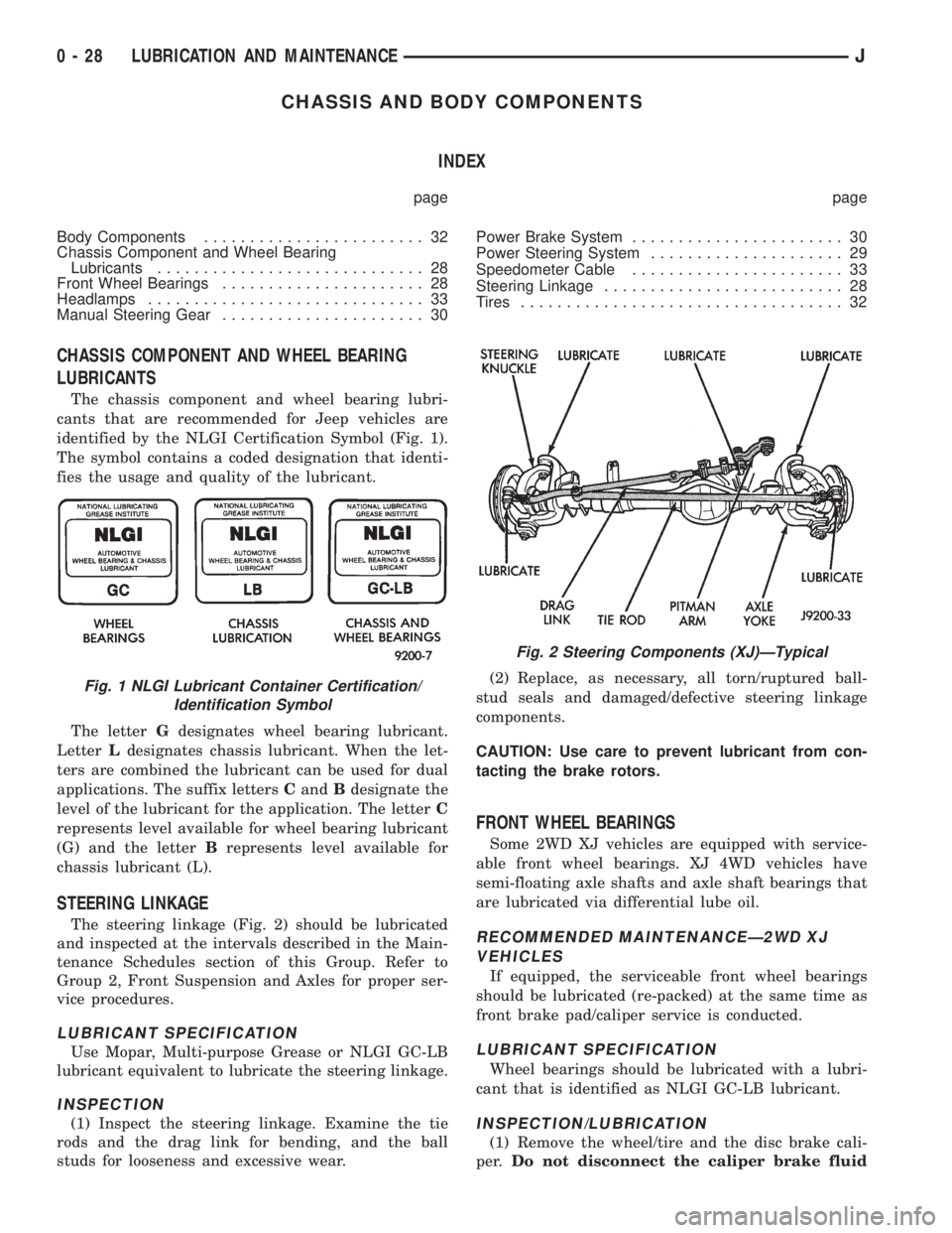
The chassis component and wheel bearing lubri-
cants that are recommended for Jeep vehicles are
identified by the NLGI Certification Symbol (Fig. 1).
The symbol contains a coded designation that identi-
fies the usage and quality of the lubricant.
The letterGdesignates wheel bearing lubricant.
LetterLdesignates chassis lubricant. When the let-
ters are combined the lubricant can be used for dual
applications. The suffix lettersCandBdesignate the
level of the lubricant for the application. The letterC
represents level available for wheel bearing lubricant
(G) and the letterBrepresents level available for
chassis lubricant (L).
STEERING LINKAGE
The steering linkage (Fig. 2) should be lubricated
and inspected at the intervals described in the Main-
tenance Schedules section of this Group. Refer to
Group 2, Front Suspension and Axles for proper ser-
vice procedures.
LUBRICANT SPECIFICATION
Use Mopar, Multi-purpose Grease or NLGI GC-LB
lubricant equivalent to lubricate the steering linkage.
INSPECTION
(1) Inspect the steering linkage. Examine the tie
rods and the drag link for bending, and the ball
studs for looseness and excessive wear.(2) Replace, as necessary, all torn/ruptured ball-
stud seals and damaged/defective steering linkage
components.
CAUTION: Use care to prevent lubricant from con-
tacting the brake rotors.
FRONT WHEEL BEARINGS
Some 2WD XJ vehicles are equipped with service-
able front wheel bearings. XJ 4WD vehicles have
semi-floating axle shafts and axle shaft bearings that
are lubricated via differential lube oil.
RECOMMENDED MAINTENANCEÐ2WD XJ
VEHICLES
If equipped, the serviceable front wheel bearings
should be lubricated (re-packed) at the same time as
front brake pad/caliper service is conducted.
LUBRICANT SPECIFICATION
Wheel bearings should be lubricated with a lubri-
cant that is identified as NLGI GC-LB lubricant.
INSPECTION/LUBRICATION
(1) Remove the wheel/tire and the disc brake cali-
per.Do not disconnect the caliper brake fluid
Fig. 1 NLGI Lubricant Container Certification/
Identification Symbol
Fig. 2 Steering Components (XJ)ÐTypical
0 - 28 LUBRICATION AND MAINTENANCEJ
Page 30 of 2198
hose unless the caliper must also be removed
for maintenance.Support the caliper with a
hanger to prevent brake fluid hose damage.
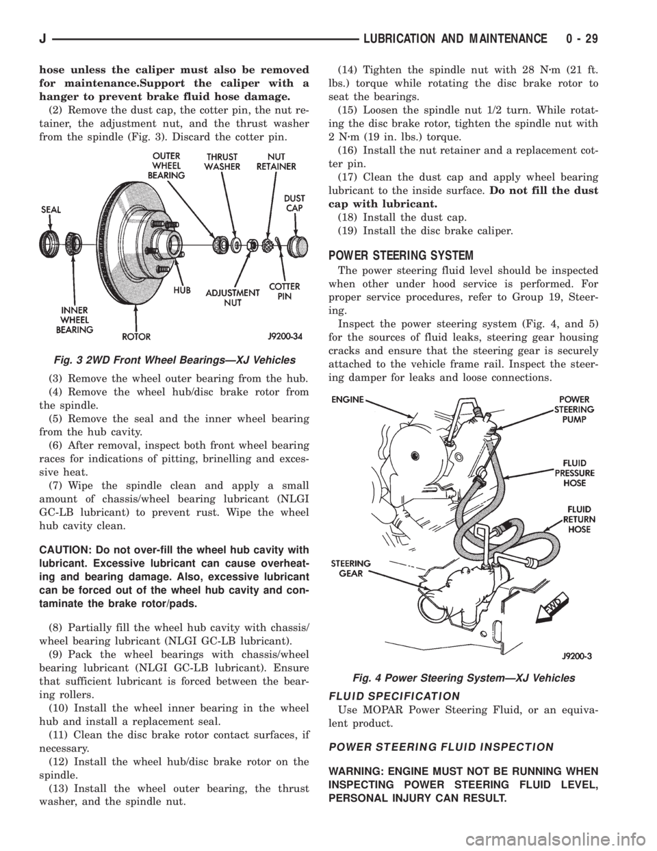
(2) Remove the dust cap, the cotter pin, the nut re-
tainer, the adjustment nut, and the thrust washer
from the spindle (Fig. 3). Discard the cotter pin.
(3) Remove the wheel outer bearing from the hub.
(4) Remove the wheel hub/disc brake rotor from
the spindle.
(5) Remove the seal and the inner wheel bearing
from the hub cavity.
(6) After removal, inspect both front wheel bearing
races for indications of pitting, brinelling and exces-
sive heat.
(7) Wipe the spindle clean and apply a small
amount of chassis/wheel bearing lubricant (NLGI
GC-LB lubricant) to prevent rust. Wipe the wheel
hub cavity clean.
CAUTION: Do not over-fill the wheel hub cavity with
lubricant. Excessive lubricant can cause overheat-
ing and bearing damage. Also, excessive lubricant
can be forced out of the wheel hub cavity and con-
taminate the brake rotor/pads.
(8) Partially fill the wheel hub cavity with chassis/
wheel bearing lubricant (NLGI GC-LB lubricant).
(9) Pack the wheel bearings with chassis/wheel
bearing lubricant (NLGI GC-LB lubricant). Ensure
that sufficient lubricant is forced between the bear-
ing rollers.
(10) Install the wheel inner bearing in the wheel
hub and install a replacement seal.
(11) Clean the disc brake rotor contact surfaces, if
necessary.
(12) Install the wheel hub/disc brake rotor on the
spindle.
(13) Install the wheel outer bearing, the thrust
washer, and the spindle nut.(14) Tighten the spindle nut with 28 Nzm (21 ft.
lbs.) torque while rotating the disc brake rotor to
seat the bearings.
(15) Loosen the spindle nut 1/2 turn. While rotat-
ing the disc brake rotor, tighten the spindle nut with
2Nzm (19 in. lbs.) torque.
(16) Install the nut retainer and a replacement cot-
ter pin.
(17) Clean the dust cap and apply wheel bearing
lubricant to the inside surface.Do not fill the dust
cap with lubricant.
(18) Install the dust cap.
(19) Install the disc brake caliper.
POWER STEERING SYSTEM
The power steering fluid level should be inspected
when other under hood service is performed. For
proper service procedures, refer to Group 19, Steer-
ing.
Inspect the power steering system (Fig. 4, and 5)
for the sources of fluid leaks, steering gear housing
cracks and ensure that the steering gear is securely
attached to the vehicle frame rail. Inspect the steer-
ing damper for leaks and loose connections.
FLUID SPECIFICATION
Use MOPAR Power Steering Fluid, or an equiva-
lent product.
POWER STEERING FLUID INSPECTION
WARNING: ENGINE MUST NOT BE RUNNING WHEN
INSPECTING POWER STEERING FLUID LEVEL,
PERSONAL INJURY CAN RESULT.
Fig. 3 2WD Front Wheel BearingsÐXJ Vehicles
Fig. 4 Power Steering SystemÐXJ Vehicles
JLUBRICATION AND MAINTENANCE 0 - 29
Page 31 of 2198
FLUID LEVEL
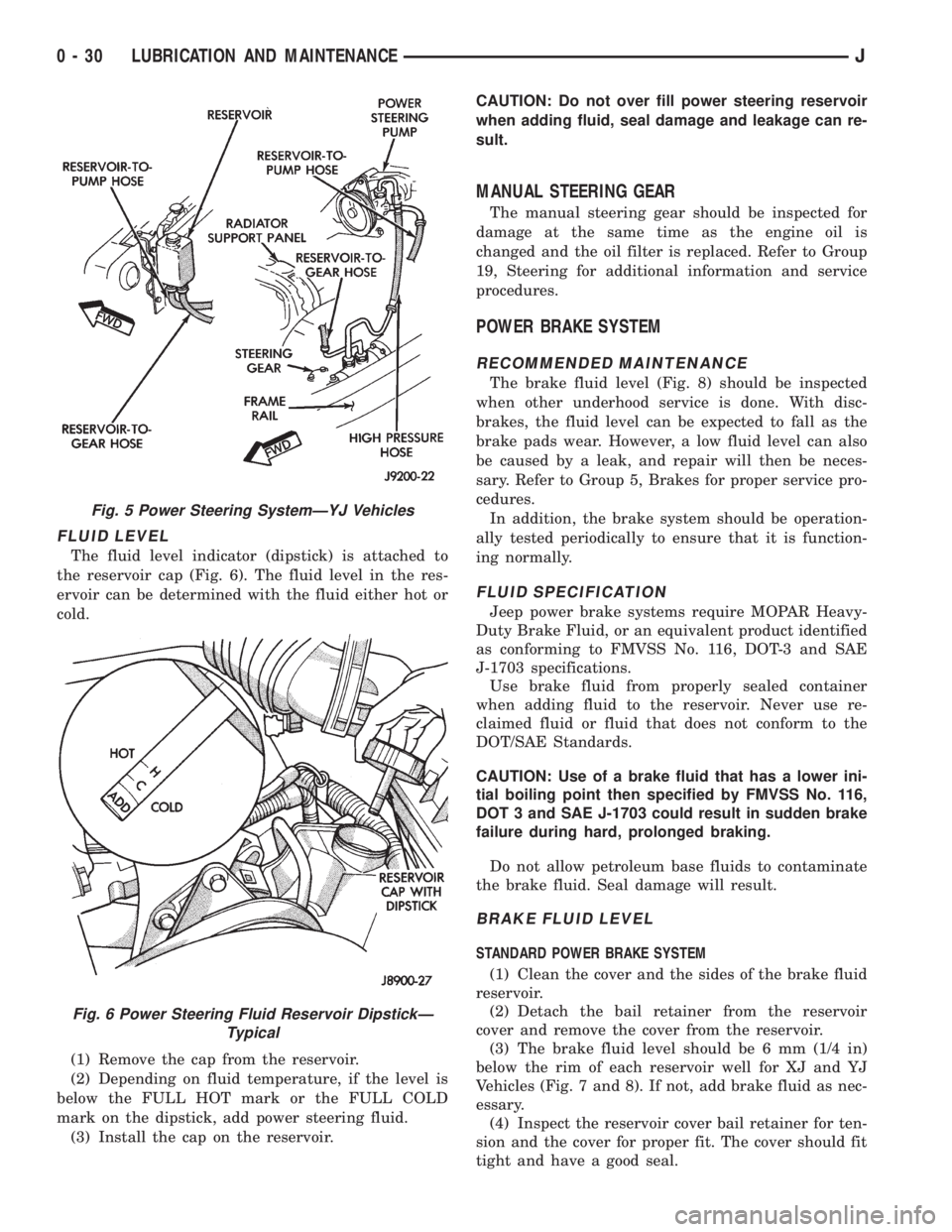
The fluid level indicator (dipstick) is attached to
the reservoir cap (Fig. 6). The fluid level in the res-
ervoir can be determined with the fluid either hot or
cold.
(1) Remove the cap from the reservoir.
(2) Depending on fluid temperature, if the level is
below the FULL HOT mark or the FULL COLD
mark on the dipstick, add power steering fluid.
(3) Install the cap on the reservoir.CAUTION: Do not over fill power steering reservoir
when adding fluid, seal damage and leakage can re-
sult.
MANUAL STEERING GEAR
The manual steering gear should be inspected for
damage at the same time as the engine oil is
changed and the oil filter is replaced. Refer to Group
19, Steering for additional information and service
procedures.
POWER BRAKE SYSTEM
RECOMMENDED MAINTENANCE
The brake fluid level (Fig. 8) should be inspected
when other underhood service is done. With disc-
brakes, the fluid level can be expected to fall as the
brake pads wear. However, a low fluid level can also
be caused by a leak, and repair will then be neces-
sary. Refer to Group 5, Brakes for proper service pro-
cedures.
In addition, the brake system should be operation-
ally tested periodically to ensure that it is function-
ing normally.
FLUID SPECIFICATION
Jeep power brake systems require MOPAR Heavy-
Duty Brake Fluid, or an equivalent product identified
as conforming to FMVSS No. 116, DOT-3 and SAE
J-1703 specifications.
Use brake fluid from properly sealed container
when adding fluid to the reservoir. Never use re-
claimed fluid or fluid that does not conform to the
DOT/SAE Standards.
CAUTION: Use of a brake fluid that has a lower ini-
tial boiling point then specified by FMVSS No. 116,
DOT 3 and SAE J-1703 could result in sudden brake
failure during hard, prolonged braking.
Do not allow petroleum base fluids to contaminate
the brake fluid. Seal damage will result.
BRAKE FLUID LEVEL
STANDARD POWER BRAKE SYSTEM
(1) Clean the cover and the sides of the brake fluid
reservoir.
(2) Detach the bail retainer from the reservoir
cover and remove the cover from the reservoir.
(3) The brake fluid level should be 6 mm (1/4 in)
below the rim of each reservoir well for XJ and YJ
Vehicles (Fig. 7 and 8). If not, add brake fluid as nec-
essary.
(4) Inspect the reservoir cover bail retainer for ten-
sion and the cover for proper fit. The cover should fit
tight and have a good seal.
Fig. 5 Power Steering SystemÐYJ Vehicles
Fig. 6 Power Steering Fluid Reservoir DipstickÐ
Typical
0 - 30 LUBRICATION AND MAINTENANCEJ
Page 141 of 2198
SERVICE BRAKE DIAGNOSIS
INDEX
page page
Brake Drag............................... 6
Brake Fade.............................. 6
Brake Fluid Contamination................... 7
Brake Noise.............................. 7
Brake Pull............................... 6
Brake Warning Light Operation................ 5
Brakes Do Not Hold After Driving Through Deep
Water Puddles........................... 7
Component Inspection...................... 5
Contaminated Brakelining.................... 7
Diagnosing Parking Brake Malfunctions.......... 8
Diagnosis Procedures....................... 4
General Information........................ 4Hard Pedal or High Pedal Effort............... 6
Low Pedal............................... 5
Master Cylinder/Power Booster Test............ 8
Pedal Falls Away.......................... 5
Pedal Pulsation (Non-ABS Brakes Only)......... 6
Power Booster Check Valve Test............... 9
Power Booster Vacuum Test.................. 9
Preliminary Brake Check..................... 4
Rear Brake Grab.......................... 7
Road Testing............................. 5
Spongy Pedal............................. 5
Wheel and Tire Problems.................... 7
GENERAL INFORMATION
The diagnosis information in this section covers
service brake components which include:
²disc brake calipers
²disc brakeshoes
²drum brake wheel cylinders
²drum brakeshoes and brake drums
²drum brake support plates
²parking brake mechanism
²master cylinder/combination valve
²vacuum power brake booster
²brake pedal and brakelight switch
²brake warning light
DIAGNOSIS PROCEDURES
Service brake diagnosis involves determining if a
problem is related to a mechanical, hydraulic or vac-
uum operated component. A preliminary brake check,
followed by road testing and component inspection
are needed to determine a problem cause.
Road testing will either verify proper brake opera-
tion or confirm the existence of a problem. Compo-
nent inspection will, in most cases, identify the
actual part responsible for a problem.
The first diagnosis step is the preliminary brake
check. This involves inspecting fluid level, parking
brake action, wheel and tire condition, checking for
obvious leaks or component damage and testing
brake pedal response. A road test will confirm or
deny the existence of a problem. The final diagnosis
procedure involves road test analysis and a visual in-
spection of brake components.
PRELIMINARY BRAKE CHECK
(1) If amber ABS light is illuminated, refer to ABS
Brake System Diagnosis. If red warning light is illu-
minated, or if neither warning light is illuminated,
continue with brake check.(2) Inspect condition of tires and wheels. Damaged
wheels and worn, damaged, or underinflated tires
can cause pull, shudder, tramp and a condition simi-
lar to grab.
(3) If complaint was based on noise when braking,
check suspension components. Jounce front and rear
of vehicle and listen for noise that might be caused
by loose, worn, or damaged suspension or steering
components.
(4) Inspect brake fluid level:
(a) If vehicle has one-piece master cylinder, fluid
level should be within 6 mm (1/4 in.) of reservoir
rim.
(b) If vehicle has nylon reservoir with single
filler cap, correct level is to FULL mark on side of
reservoir. Acceptable level is between FULL and
ADD marks.
(c) Remember that fluid level in the reservoir
compartments will decrease in proportion to nor-
mal lining wear. However, if fluid level is abnor-
mally low, look for leaks at calipers, wheel
cylinders, brakelines and master cylinder.
(5) Inspect brake fluid condition:
(a) Fluid should be free of foreign material.Note
that brake fluid tends to darken over time.
This is normal and should not be mistaken for
contamination. If fluid is clear of foreign ma-
terial, it is OK.
(b) If fluid is highly discolored, or appears to con-
tain foreign material, drain out a sample with a
clean suction gun. Pour sample in a glass container
and note condition described in step (c).
(c) If fluid separates into layers, obviously con-
tains oil, or a substance other than brake fluid,
system seals and cups will have to be replaced and
hydraulic system flushed.
(6) Check parking brake operation. Verify free
movement and full release of cables and foot pedal or
5 - 4 SERVICE BRAKE DIAGNOSISJ
Page 170 of 2198
ABS OPERATION AND SERVICE
INDEX
page page
ABS Component Serviceability............... 37
ABS Diagnostic Connector.................. 35
ABS Operation in Antilock Braking Mode........ 36
ABS Operation in Normal Braking Mode........ 35
ABS System Power-Up and Initialization........ 35
Acceleration Switch........................ 35
Acceleration Switch Installation............... 39
Acceleration Switch Operation................ 37
Acceleration Switch Removal................ 39
Combination Valve........................ 34
ECU Installation (XJ Models)................. 40
ECU Operation........................... 37
ECU Removal (XJ Models).................. 40
ECU Removal/Installation (YJ Models).......... 41
Electronic Control Unit (ECU)................ 34
Front Wheel Sensor Installation............... 38
Front Wheel Sensor Removal................ 38HCU Installation (XJ)....................... 43
HCU Installation (YJ)....................... 44
HCU Operation........................... 36
HCU Removal (XJ)........................ 41
HCU Removal (YJ)........................ 44
Hydraulic Control Unit (HCU)................. 33
Ignition Switch........................... 35
Master Cylinder/Power Brake Booster.......... 34
Rear Wheel Sensor Installation and Adjustment . . . 38
Rear Wheel Sensor Removal................ 38
Speed Sensor Air Gap..................... 37
System Description........................ 33
System Relays........................... 35
System Warning Light...................... 35
Wheel Speed Sensor Operation.............. 37
Wheel Speed Sensors..................... 34
SYSTEM DESCRIPTION
The Jeep antilock brake system (ABS) is an elec-
tronically operated, all wheel brake control system.
The system is designed to prevent wheel lockup
and maintain steering control during periods of high
wheel slip when braking. Preventing lockup is accom-
plished by modulating fluid pressure to the wheel
brake units.
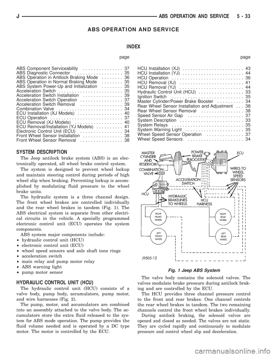
The hydraulic system is a three channel design.
The front wheel brakes are controlled individually
and the rear wheel brakes in tandem (Fig. 1). The
ABS electrical system is separate from other electri-
cal circuits in the vehicle. A specially programmed
electronic control unit (ECU) operates the system
components.
ABS system major components include:
²hydraulic control unit (HCU)
²electronic control unit (ECU)
²wheel speed sensors and axle shaft tone rings
²acceleration switch
²main relay and pump motor relay
²ABS warning light
²pump motor sensor
HYDRAULIC CONTROL UNIT (HCU)
The hydraulic control unit (HCU) consists of a
valve body, pump body, accumulators, pump motor,
and wire harnesses (Fig. 2).
The pump, motor, and accumulators are combined
into an assembly attached to the valve body. The ac-
cumulators store the extra fluid released to the sys-
tem for ABS mode operation. The pump provides the
fluid volume needed and is operated by a DC type
motor. The motor is controlled by the ECU.The valve body contains the solenoid valves. The
valves modulate brake pressure during antilock brak-
ing and are controlled by the ECU.
The HCU provides three channel pressure control
to the front and rear brakes. One channel controls
the rear wheel brakes in tandem. The two remaining
channels control the front wheel brakes individually.
During antilock braking, the solenoid valves are
opened and closed as needed. The valves are not static.
They are cycled rapidly and continuously to modulate
pressure and control wheel slip and deceleration.
Fig. 1 Jeep ABS System
JABS OPERATION AND SERVICE 5 - 33
Page 171 of 2198
MASTER CYLINDER/POWER BRAKE BOOSTER
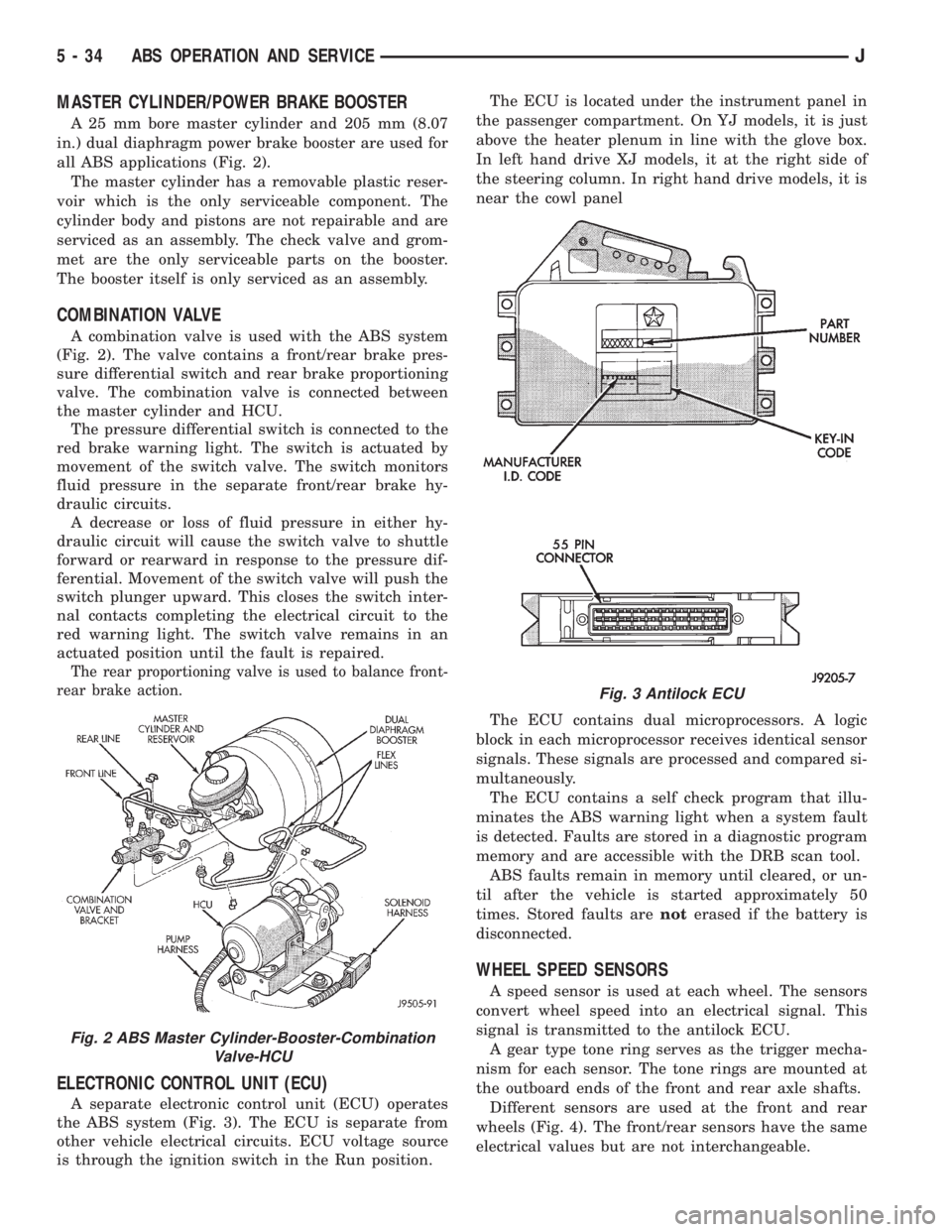
A 25 mm bore master cylinder and 205 mm (8.07
in.) dual diaphragm power brake booster are used for
all ABS applications (Fig. 2).
The master cylinder has a removable plastic reser-
voir which is the only serviceable component. The
cylinder body and pistons are not repairable and are
serviced as an assembly. The check valve and grom-
met are the only serviceable parts on the booster.
The booster itself is only serviced as an assembly.
COMBINATION VALVE
A combination valve is used with the ABS system
(Fig. 2). The valve contains a front/rear brake pres-
sure differential switch and rear brake proportioning
valve. The combination valve is connected between
the master cylinder and HCU.
The pressure differential switch is connected to the
red brake warning light. The switch is actuated by
movement of the switch valve. The switch monitors
fluid pressure in the separate front/rear brake hy-
draulic circuits.
A decrease or loss of fluid pressure in either hy-
draulic circuit will cause the switch valve to shuttle
forward or rearward in response to the pressure dif-
ferential. Movement of the switch valve will push the
switch plunger upward. This closes the switch inter-
nal contacts completing the electrical circuit to the
red warning light. The switch valve remains in an
actuated position until the fault is repaired.
The rear proportioning valve is used to balance front-
rear brake action.
ELECTRONIC CONTROL UNIT (ECU)
A separate electronic control unit (ECU) operates
the ABS system (Fig. 3). The ECU is separate from
other vehicle electrical circuits. ECU voltage source
is through the ignition switch in the Run position.The ECU is located under the instrument panel in
the passenger compartment. On YJ models, it is just
above the heater plenum in line with the glove box.
In left hand drive XJ models, it at the right side of
the steering column. In right hand drive models, it is
near the cowl panel
The ECU contains dual microprocessors. A logic
block in each microprocessor receives identical sensor
signals. These signals are processed and compared si-
multaneously.
The ECU contains a self check program that illu-
minates the ABS warning light when a system fault
is detected. Faults are stored in a diagnostic program
memory and are accessible with the DRB scan tool.
ABS faults remain in memory until cleared, or un-
til after the vehicle is started approximately 50
times. Stored faults arenoterased if the battery is
disconnected.
WHEEL SPEED SENSORS
A speed sensor is used at each wheel. The sensors
convert wheel speed into an electrical signal. This
signal is transmitted to the antilock ECU.
A gear type tone ring serves as the trigger mecha-
nism for each sensor. The tone rings are mounted at
the outboard ends of the front and rear axle shafts.
Different sensors are used at the front and rear
wheels (Fig. 4). The front/rear sensors have the same
electrical values but are not interchangeable.
Fig. 2 ABS Master Cylinder-Booster-Combination
Valve-HCU
Fig. 3 Antilock ECU
5 - 34 ABS OPERATION AND SERVICEJ
Page 173 of 2198
During normal braking, the master cylinder, power
booster and wheel brake units all function as they
would in a vehicle without ABS. The HCU compo-
nents are not activated.
ABS OPERATION IN ANTILOCK BRAKING MODE
The purpose of the antilock system is to prevent
wheel lockup during periods of high wheel slip. Pre-
venting lockup helps maintain vehicle braking action
and steering control.
The antilock ECU activates the system whenever
sensor signals indicate periods of high wheel slip.
High wheel slip can be described as the point where
wheel rotation begins approaching zero (or lockup)
during braking. Periods of high wheel slip may occur
when brake stops involve high pedal pressure and
rate of deceleration.
The antilock system prevents lockup during high
slip conditions by modulating fluid apply pressure to
the wheel brake units.
Brake fluid apply pressure is modulated according
to wheel speed, degree of slip and rate of decelera-
tion. A sensor at each wheel converts wheel speed
into electrical signals. These signals are transmitted
to the ECU for processing and determination of
wheel slip and deceleration rate.
The ABS system has three fluid pressure control
channels. The front brakes are controlled separately
and the rear brakes in tandem (Fig. 1). A speed sen-
sor input signal indicating a high slip condition acti-
vates the ECU antilock program.
Two solenoid valves are used in each antilock con-
trol channel. The valves are all located within the
HCU valve body and work in pairs to either increase,
hold, or decrease apply pressure as needed in the in-
dividual control channels.
The solenoid valves are not static during antilock
braking. They are cycled continuously to modulate
pressure. Solenoid cycle time in antilock mode can be
measured in milliseconds.
HCU OPERATION
Normal Braking
During normal braking, the HCU solenoid valves
and pump are not activated. The master cylinder and
power booster operate the same as a vehicle without
an ABS brake system.
Antilock Pressure Modulation
Solenoid valve pressure modulation occurs in three
stages which are: pressure increase, pressure hold,
and pressure decrease. The valves are all contained
in the valve body portion of the HCU.
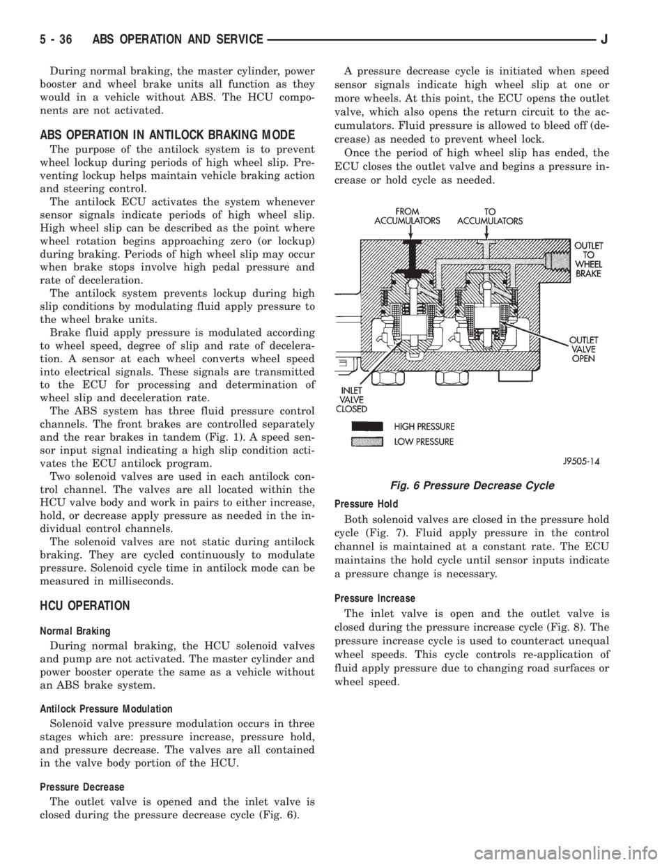
Pressure Decrease
The outlet valve is opened and the inlet valve is
closed during the pressure decrease cycle (Fig. 6).A pressure decrease cycle is initiated when speed
sensor signals indicate high wheel slip at one or
more wheels. At this point, the ECU opens the outlet
valve, which also opens the return circuit to the ac-
cumulators. Fluid pressure is allowed to bleed off (de-
crease) as needed to prevent wheel lock.
Once the period of high wheel slip has ended, the
ECU closes the outlet valve and begins a pressure in-
crease or hold cycle as needed.
Pressure Hold
Both solenoid valves are closed in the pressure hold
cycle (Fig. 7). Fluid apply pressure in the control
channel is maintained at a constant rate. The ECU
maintains the hold cycle until sensor inputs indicate
a pressure change is necessary.
Pressure Increase
The inlet valve is open and the outlet valve is
closed during the pressure increase cycle (Fig. 8). The
pressure increase cycle is used to counteract unequal
wheel speeds. This cycle controls re-application of
fluid apply pressure due to changing road surfaces or
wheel speed.
Fig. 6 Pressure Decrease Cycle
5 - 36 ABS OPERATION AND SERVICEJ
Page 256 of 2198
WAYS WEAR SAFETY GLASSES WHEN SERVICING
CONSTANT TENSION CLAMPS.
CAUTION: A number or letter is stamped into the
tongue of constant tension clamps (Fig. 28). If re-
placement is necessary, use only an original equip-
ment clamp with matching number or letter.
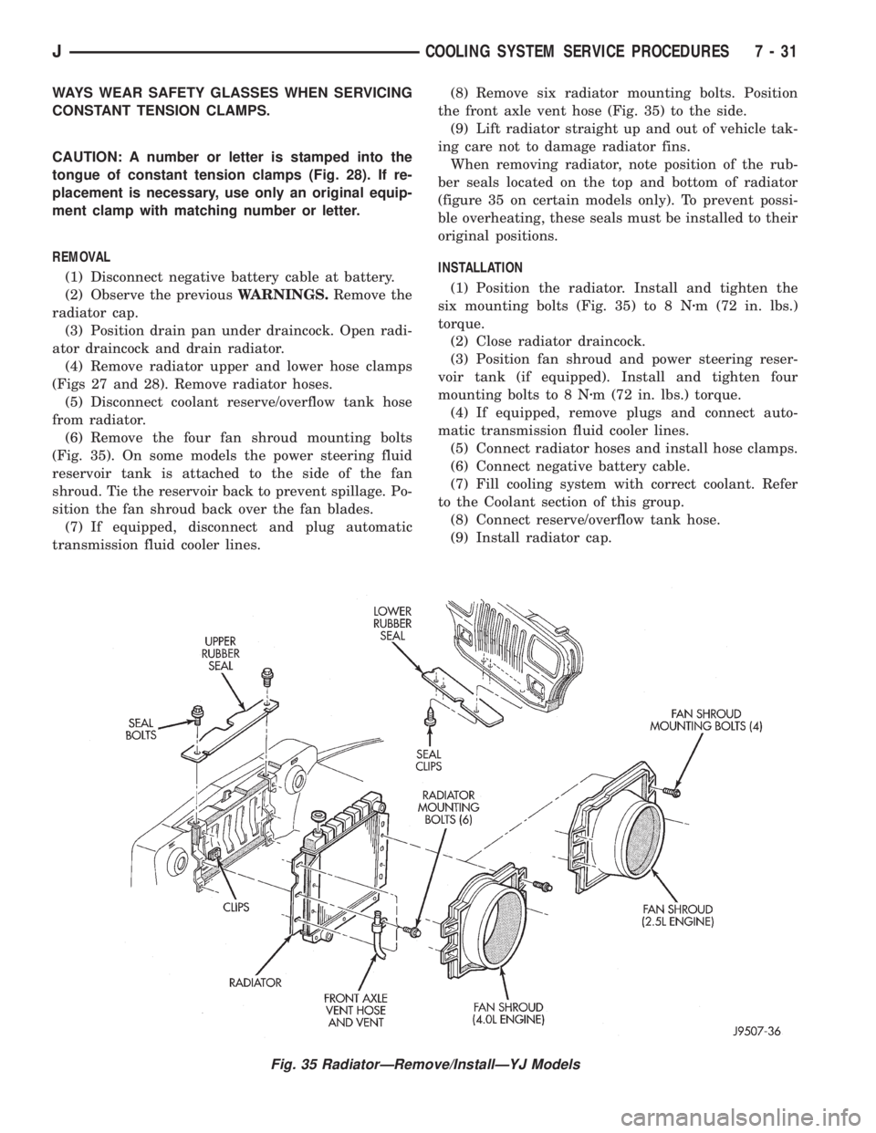
REMOVAL
(1) Disconnect negative battery cable at battery.
(2) Observe the previousWARNINGS.Remove the
radiator cap.
(3) Position drain pan under draincock. Open radi-
ator draincock and drain radiator.
(4) Remove radiator upper and lower hose clamps
(Figs 27 and 28). Remove radiator hoses.
(5) Disconnect coolant reserve/overflow tank hose
from radiator.
(6) Remove the four fan shroud mounting bolts
(Fig. 35). On some models the power steering fluid
reservoir tank is attached to the side of the fan
shroud. Tie the reservoir back to prevent spillage. Po-
sition the fan shroud back over the fan blades.
(7) If equipped, disconnect and plug automatic
transmission fluid cooler lines.(8) Remove six radiator mounting bolts. Position
the front axle vent hose (Fig. 35) to the side.
(9) Lift radiator straight up and out of vehicle tak-
ing care not to damage radiator fins.
When removing radiator, note position of the rub-
ber seals located on the top and bottom of radiator
(figure 35 on certain models only). To prevent possi-
ble overheating, these seals must be installed to their
original positions.
INSTALLATION
(1) Position the radiator. Install and tighten the
six mounting bolts (Fig. 35) to 8 Nzm (72 in. lbs.)
torque.
(2) Close radiator draincock.
(3) Position fan shroud and power steering reser-
voir tank (if equipped). Install and tighten four
mounting bolts to 8 Nzm (72 in. lbs.) torque.
(4) If equipped, remove plugs and connect auto-
matic transmission fluid cooler lines.
(5) Connect radiator hoses and install hose clamps.
(6) Connect negative battery cable.
(7) Fill cooling system with correct coolant. Refer
to the Coolant section of this group.
(8) Connect reserve/overflow tank hose.
(9) Install radiator cap.
Fig. 35 RadiatorÐRemove/InstallÐYJ Models
JCOOLING SYSTEM SERVICE PROCEDURES 7 - 31
Page 580 of 2198
Circuit T17 from fuse 3 in the power distribution
center supplies voltage to the coil and contact sides
of the TCC relay. When the PCM provides a ground
path on circuit K54 for the coil side of the relay, the
relay contacts close.
When the relay contacts close, they connect circuit
T17 with circuit T22. Circuit T22 supplies battery
voltage to the case grounded TCC solenoid. Circuit
K54 connects to PCM cavity 54.
HELPFUL INFORMATION
²In the RUN or START position, the ignition switch
connects circuit A1 from fuse 4 in the PDC to circuit
A21.
UPSHIFT LAMP
On vehicles equipped with a manual transmission,
the PCM grounds the up-shift lamp on circuit K54.
Circuit K54 connects to cavity 54 of the PCM.
POWER STEERING PRESSURE SWITCH
The PCM supplies voltage to the power steering
pressure switch on circuit K10. Circuit Z12 provides
ground for the switch. When the switch closes, volt-
age flows through the switch to ground on circuit
Z12. The switch closes during periods of high power
steering pump load and low engine speed; such as
parking maneuvers.
Circuit K10 connects to cavity 10 of the PCM. Cir-
cuit Z12 terminates at the right rear of the engine.
TACHOMETER SIGNAL
The PCM supplies the signal for the tachometer on
circuit G21. Circuit G21 connects to cavity 43 of the
PCM.
MALFUNCTION INDICATOR LAMP (MIL)
The PCM provides ground for the instrument clus-
ter malfunction indicator lamp on circuit G3. The
MIL displays the message CHECK ENGINE when il-
luminated. Circuit F87 provides voltage for the lamp.
DATA LINK CONNECTOR
Circuit F12 supplies battery voltage to the data
link connector. Circuit F12 originates at fuse 11 in
the Power Distribution Center.
Circuit D20 connects to cavity 45 of the PCM. Cir-
cuit D20 is the SCI receive circuit for the PCM.
Circuit D21 connects to cavity 25 of the PCM. Cir-
cuit D21 is the SCI transmit circuit for the PCM.
Circuit Z11 provides ground for the data link con-
nector. Circuit Z11 terminates at the right rear of the
engine. Circuit Z11 also connects to cavity 5 of the
PCM.
HELPFUL INFORMATION
²Circuit Z1 also supplies a ground for the PCM
high current drivers.
²If the system loses ground for the Z11 circuits at
the right rear of the engine, the vehicle will not op-
erate. Check the connection at the ganged-ground cir-
cuit eyelet.
²Circuit F12 splices to supply battery voltage to the
vehicle speed control switch, back-up lamp switch,
A/C compressor clutch relay, windshield washer fluid
level sensor and radiator fan relay (4.0L engines).
BRAKE SWITCH INPUT
Circuit K29 provides the brake switch input to the
PCM. Circuit V40 connects to cavity 29 of the PCM.
POWER (DEVICE) GROUND
Circuit Z12 connects to cavities 11 and 12 of the
PCM. The Z12 circuit provides ground for PCM inter-
nal drivers that operate high current devices like the
injectors and ignition coil.
Internal to the PCM, the power (device) ground cir-
cuit connects to the PCM sensor return circuit (from
circuit K4).
HELPFUL INFORMATION
²The grounding point for circuit Z12 is the right
rear of the engine.
²If the system loses ground for the Z12 circuits at
the rear of the engine, the vehicle will not operate.
Check the connection at the ganged-ground circuit
eyelet.
²On vehicles equipped with the 4.0L engine and au-
tomatic transmission, circuit Z12 splices to provide
ground for the transmission control module.
EXTENDED IDLE SWITCH
On Police Package vehicles, an optional extended
idle switch provides an input to the Powertrain Con-
trol Module (PCM) on circuit K10. Circuit K10 con-
nects to cavity 10 of the PCM. Circuit F60 supplies
battery voltage to the extended idle switch. Circuit
Z1 grounds the switch.
CCD BUS
On vehicles equipped with the 4.0L engine, circuits
D1 and D2 connect the Powertrain Control Module
(PCM) to the CCD Bus. Circuit D1 connects to cavity
26 of the PCM. Circuit D2 connects to cavity 46 of
the PCM. Circuits D1 and D2 are a twisted pair of
wires.
J8W-30 FUEL/IGNITIONÐXJ VEHICLES 8W - 30 - 5