light JEEP CHEROKEE 2014 KL / 5.G User Guide
[x] Cancel search | Manufacturer: JEEP, Model Year: 2014, Model line: CHEROKEE, Model: JEEP CHEROKEE 2014 KL / 5.GPages: 204, PDF Size: 3.84 MB
Page 3 of 204
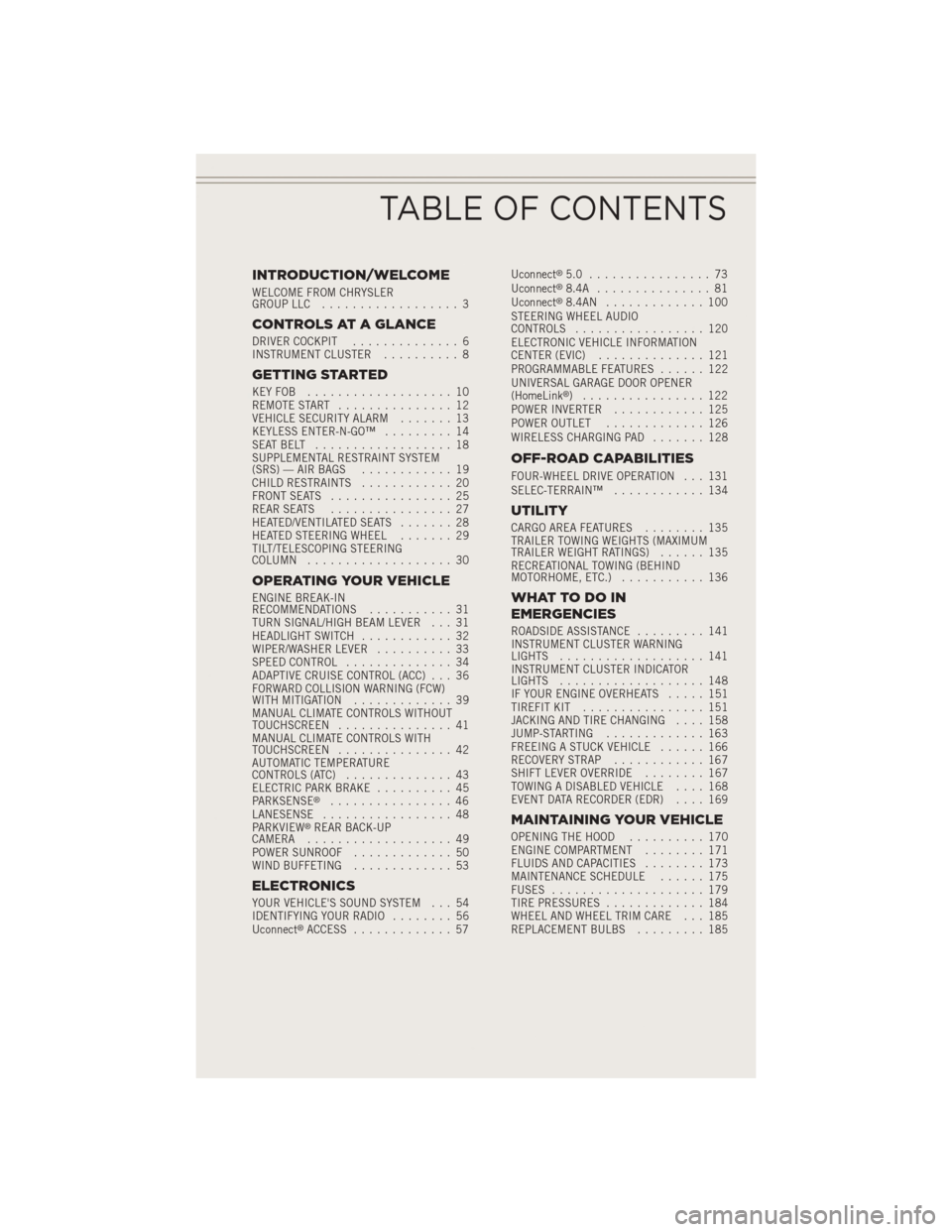
INTRODUCTION/WELCOME
WELCOME FROM CHRYSLER
GROUP LLC.................. 3
CONTROLS AT A GLANCE
DRIVER COCKPIT .............. 6
INSTRUMENT CLUSTER .......... 8
GETTING STARTED
KEYFOB ................... 10
REMOTE START............... 12
VEHICLE SECURITY ALARM ....... 13
KEYLESS ENTER-N-GO™ ......... 14
SEATBELT .................. 18
SUPPLEMENTAL RESTRAINT SYSTEM
(SRS) — AIR BAGS ............ 19
CHILD RESTRAINTS ............ 20
FRONT SEATS ................ 25
REAR SEATS ................ 27
HEATED/VENTILATED SEATS ....... 28
HEATED STEERING WHEEL ....... 29
TILT/TELESCOPING STEERING
COLUMN ................... 30
OPERATING YOUR VEHICLE
ENGINE BREAK-IN
RECOMMENDATIONS ........... 31
TURN SIGNAL/HIGH BEAM LEVER . . . 31
HEADLIGHT SWITCH ............ 32
WIPER/WASHER LEVER .......... 33
SPEED CONTROL .............. 34
ADAPTIVE CRUISE CONTROL (ACC) . . . 36
FORWARD COLLISION WARNING (FCW)
WITHMITIGATION ............. 39
MANUAL CLIMATE CONTROLS WITHOUT
TOUCHSCREEN ............... 41
MANUAL CLIMATE CONTROLS WITH
TOUCHSCREEN ............... 42
AUTOMATIC TEMPERATURE
CONTROLS (ATC) .............. 43
ELECTRIC PARK BRAKE .......... 45
PARKSENSE
®................ 46
LANESENSE ................. 48
PARKVIEW
®REAR BACK-UP
CAMERA ................... 49
POWER SUNROOF ............. 50
WIND BUFFETING ............. 53
ELECTRONICS
YOUR VEHICLE'S SOUND SYSTEM . . . 54
IDENTIFYING YOUR RADIO ........ 56
Uconnect
®ACCESS ............. 57 Uconnect
®5.0 ................ 73
Uconnect®8.4A ............... 81
Uconnect®8.4AN ............. 100
STEERING WHEEL AUDIO
CONTROLS ................. 120
ELECTRONIC VEHICLE INFORMATION
CENTER (EVIC) .............. 121
PROGRAMMABLE FEATURES ...... 122
UNIVERSAL GARAGE DOOR OPENER
(HomeLink
®) ................ 122
POWER INVERTER ............ 125
POWER OUTLET ............. 126
WIRELESS CHARGING PAD ....... 128
OFF-ROAD CAPABILITIES
FOUR-WHEEL DRIVE OPERATION . . . 131
SELEC-TERRAIN™............ 134
UTILITY
CARGO AREA FEATURES ........ 135
TRAILER TOWING WEIGHTS (MAXIMUM
TRAILER WEIGHT RATINGS) ...... 135
RECREATIONAL TOWING (BEHIND
MOTORHOME, ETC.) ........... 136
WHATTODOIN
EMERGENCIES
ROADSIDE ASSISTANCE ......... 141
INSTRUMENT CLUSTER WARNING
LIGHTS ................... 141
INSTRUMENT CLUSTER INDICATOR
LIGHTS ................... 148
IF YOUR ENGINE OVERHEATS ..... 151
TIREFIT KIT ................ 151
JACKING AND TIRE CHANGING .... 158
JUMP-STARTING ............. 163
FREEING A STUCK VEHICLE ...... 166
RECOVERY STRAP ............ 167
SHIFT LEVER OVERRIDE ........ 167
TOWING A DISABLED VEHICLE .... 168
EVENT DATA RECORDER (EDR) .... 169
MAINTAINING YOUR VEHICLE
OPENING THE HOOD.......... 170
ENGINE COMPARTMENT ........ 171
FLUIDS AND CAPACITIES ........ 173
MAINTENANCE SCHEDULE ...... 175
FUSES .................... 179
TIRE PRESSURES ............. 184
WHEEL AND WHEEL TRIM CARE . . . 185
REPLACEMENT BULBS ......... 185
TABLE OF CONTENTS
Page 8 of 204
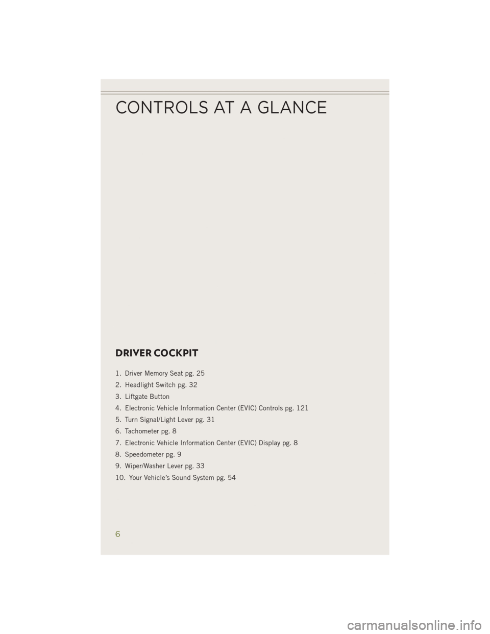
DRIVER COCKPIT
1. Driver Memory Seat pg. 25
2. Headlight Switch pg. 32
3. Liftgate Button
4. Electronic Vehicle Information Center (EVIC) Controls pg. 121
5. Turn Signal/Light Lever pg. 31
6. Tachometer pg. 8
7. Electronic Vehicle Information Center (EVIC) Display pg. 8
8. Speedometer pg. 9
9. Wiper/Washer Lever pg. 33
10. Your Vehicle’s Sound System pg. 54
CONTROLS AT A GLANCE
6
Page 10 of 204
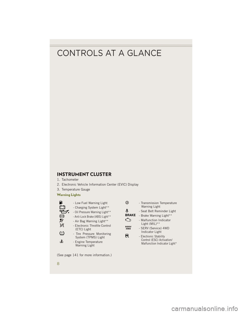
INSTRUMENT CLUSTER
1. Tachometer
2. Electronic Vehicle Information Center (EVIC) Display
3. Temperature Gauge
Warning Lights
- Low Fuel Warning Light
- Charging System Light**
- Oil Pressure Warning Light**
- Anti-Lock Brake (ABS) Light**
- Air Bag Warning Light**
- Electronic Throttle Control(ETC) Light
- Tire Pressure MonitoringSystem (TPMS) Light
- Engine TemperatureWarning Light
- Transmission TemperatureWarning Light
- Seat Belt Reminder Light
BRAKE- Brake Warning Light**
- Malfunction IndicatorLight (MIL)**
- SERV (Service) 4WDIndicator Light
-Electronic StabilityControl (ESC) Activation/
Malfunction Indicator Light*
(See page 141 for more information.)
CONTROLS AT A GLANCE
8
Page 11 of 204
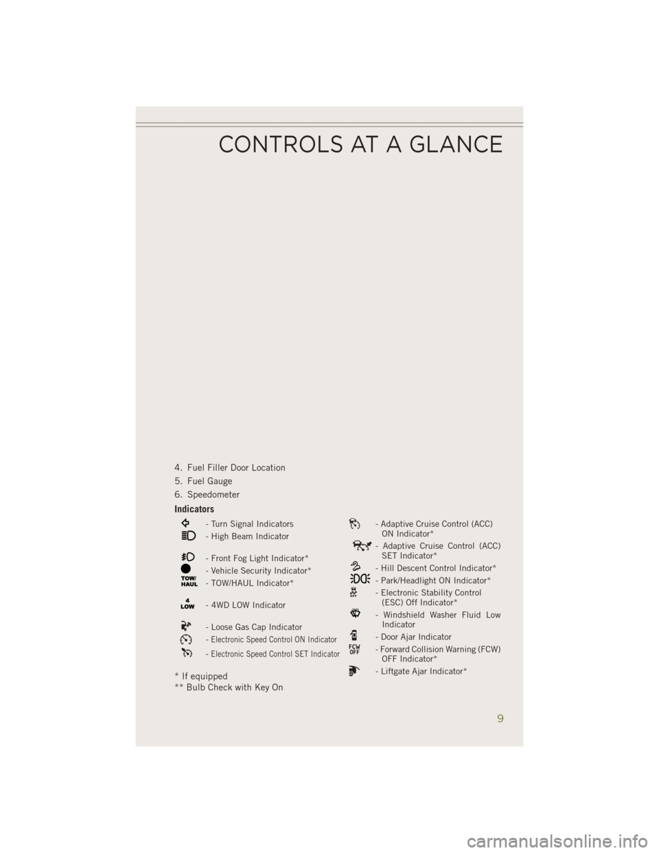
4. Fuel Filler Door Location
5. Fuel Gauge
6. Speedometer
Indicators
- Turn Signal Indicators- Adaptive Cruise Control (ACC)ON Indicator*
- High Beam Indicator- Adaptive Cruise Control (ACC)SET Indicator*
- Front Fog Light Indicator*- Hill Descent Control Indicator*- Vehicle Security Indicator*- Park/Headlight ON Indicator*- TOW/HAUL Indicator*- Electronic Stability Control(ESC) Off Indicator*
- 4WD LOW Indicator- Windshield Washer Fluid LowIndicator
- Loose Gas Cap Indicator- Door Ajar Indicator-Electronic Speed Control ON Indicator- Forward Collision Warning (FCW)OFF Indicator*-Electronic Speed Control SET Indicator
- Liftgate Ajar Indicator** If equipped
** Bulb Check with Key On
CONTROLS AT A GLANCE
9
Page 15 of 204
VEHICLE SECURITY ALARM
To Arm:
• Lock the door using either the power door lock switch (one door must be open) orthe LOCK button on the Remote Keyless Entry (RKE) transmitter (doors can be
open or closed), and close all doors.
The Vehicle Security Light in the instrument cluster will flash for 16 seconds. This
shows that the Vehicle Security Alarm is arming. During this period, if a door is
opened, the ignition is cycled to ON/RUN, or the power door locks are unlocked in any
manner, the Vehicle Security Alarm will automatically disarm.
NOTE:
• The Vehicle Security Alarm will not arm if you lock the doors with the manual door lock plungers.
• Once armed, the Vehicle Security Alarm disables the unlock switch on the driver door trim panel and passenger door trim panel.
To Disarm The System:
• Push the Key Fob UNLOCK button or cycle the ignition to the ON/RUN position.
The Vehicle Security Alarm is designed to protect your vehicle; however, you can
create conditions where the Vehicle Security Alarm will give you a false alarm. If one
of the previously described arming sequences has occurred, the Vehicle Security
Alarm will arm regardless of whether you are in the vehicle or not. If you remain in the
vehicle and open a door, the alarm will sound. If this occurs, disarm the Vehicle
Security Alarm.
If the Vehicle Security Alarm is armed and the battery becomes disconnected the
Vehicle Security Alarm will remain armed when the battery is reconnected. The
exterior lights will flash, and the horn will sound. If this occurs, disarm the Vehicle
Security Alarm.
GETTING STARTED
13
Page 21 of 204
SUPPLEMENTAL RESTRAINT SYSTEM (SRS) — AIR BAGS
• This vehicle has Advanced Front Air Bags for both the driver and front passengeras a supplement to the seat belt restraint systems. The driver's Advanced Front Air
Bag is mounted in the center of the steering wheel. The passenger's Advanced
Front Air Bag is mounted in the instrument panel, above the glove compartment.
The words SRS AIRBAG are embossed on the air bag covers. In addition, the
vehicle is equipped with a Supplemental Driver Side Knee Air Bag mounted in the
instrument panel below the steering column and a Supplemental Passenger Side
Knee Air Bag mounted in the instrument panel below the glove compartment.
NOTE:
The Driver and Front Passenger Advanced Front Air Bags are certified to the new
Federal regulations for Advanced Air Bags.
• The Advanced Front Air Bags have a multistage inflator design. This allows the air bag to have different rates of inflation based on several factors, including the
severity and type of collision.
• This vehicle may be equipped with driver and/or front passenger seat track position sensors that may adjust the inflation rate of the Advanced Front Air Bags
based upon seat position.
•
If the Air Bag Warning Lightis not on during starting, stays on, or turns on while
driving, have the vehicle serviced by an authorized service dealer immediately.
•This vehicle may be equipped with a driver and/or front passenger seat belt buckle
switch that detects whether the driver or front passenger seat belt is fastened. The
seat belt buckle switch may adjust the inflation rate of the Advanced Front Air Bags.
• This vehicle is equipped with Supplemental Side Air Bag Inflatable Curtains (SABIC) to protect the driver, front, and rear passengers sitting next to a window.
The SABIC air bags, are located above the side windows and their covers are also
labeled: SRS AIRBAG.
• This vehicle is equipped with Supplemental Seat-Mounted Side Air Bags (SAB) to provide enhanced protection for an occupant during a side impact. The Supple-
mental Seat-Mounted Side Air Bags are located in the outboard side of the front
and rear seats.
• This vehicle may be equipped with a front passenger Occupant Classification System (OCS) that may adjust the inflation rate of the Advanced Front Air Bags
based upon occupant weight.
NOTE: • Air Bag covers may not be obvious in the interior trim, but they will open duringair bag deployment.
• After any collision, the vehicle should be taken to an authorized dealer immediately.
• Refer to the Owner's Manual on the DVD for further details regarding the Supplemental Restraint System (SRS).
GETTING STARTED
19
Page 33 of 204
ENGINE BREAK-IN RECOMMENDATIONS
A long break-in period is not required for the engine and drivetrain (transmission and
axle) in your vehicle.
Drive moderately during the first 300 miles (500 km). After the initial 60 miles
(100 km), speeds up to 50 or 55 mph (80 or 90 km/h) are desirable.
While cruising, brief full-throttle acceleration within the limits of local traffic laws
contributes to a good break-in. Wide-open throttle acceleration in low gear can be
detrimental and should be avoided.
The engine oil installed in the engine at the factory is a high-quality energy
conserving type lubricant. Oil changes should be consistent with anticipated climate
conditions under which vehicle operations will occur. For the recommended viscosity
and quality grades, refer to “Maintaining Your Vehicle.”
NOTE:
A new engine may consume some oil during its first few thousand miles (kilometers)
of operation. This should be considered a normal part of the break-in and not
interpreted as an indication of an engine problem or malfunction.
CAUTION!
Never use Non-Detergent Oil or Straight Mineral Oil in the engine or damage may result.
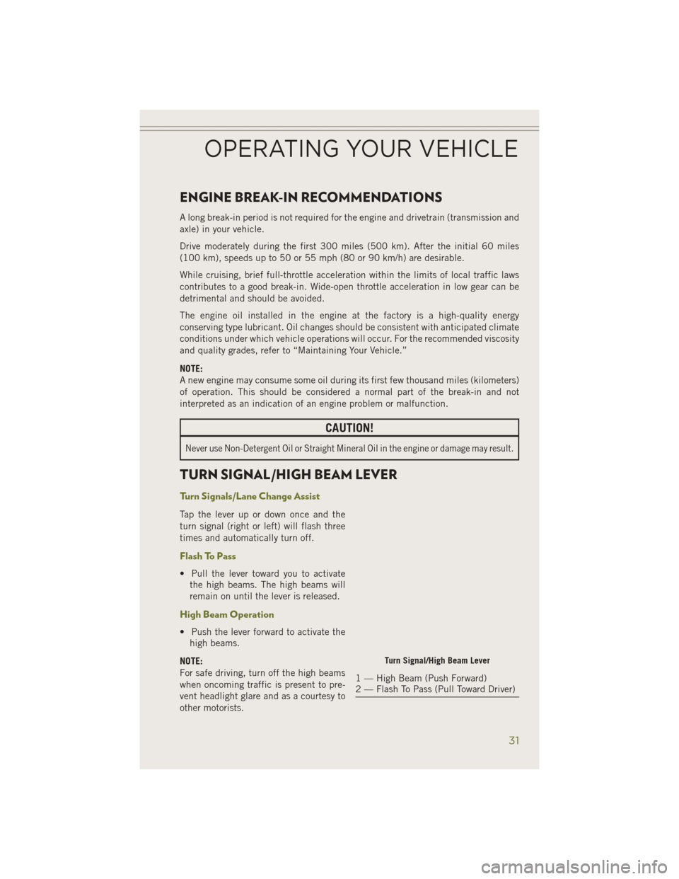
TURN SIGNAL/HIGH BEAM LEVER
Turn Signals/Lane Change Assist
Tap the lever up or down once and the
turn signal (right or left) will flash three
times and automatically turn off.
Flash To Pass
• Pull the lever toward you to activatethe high beams. The high beams will
remain on until the lever is released.
High Beam Operation
• Push the lever forward to activate thehigh beams.
NOTE:
For safe driving, turn off the high beams
when oncoming traffic is present to pre-
vent headlight glare and as a courtesy to
other motorists.
Turn Signal/High Beam Lever
1 — High Beam (Push Forward)
2 — Flash To Pass (Pull Toward Driver)
OPERATING YOUR VEHICLE
31
Page 34 of 204
HEADLIGHT SWITCH
Automatic Headlights/Parking
Lights/Headlights
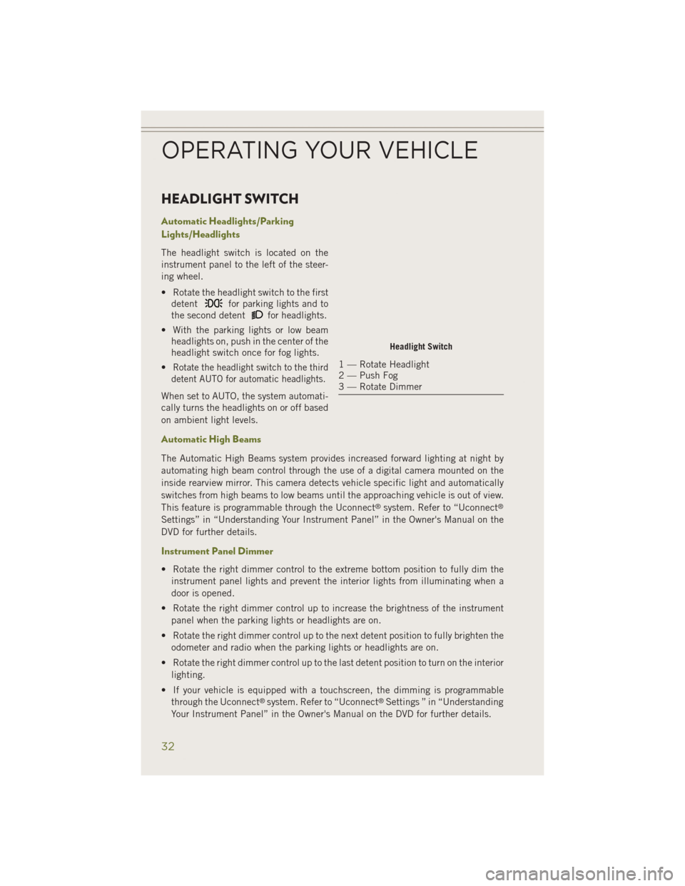
The headlight switch is located on the
instrument panel to the left of the steer-
ing wheel.
• Rotate the headlight switch to the firstdetent
for parking lights and to
the second detent
for headlights.
• With the parking lights or low beam headlights on, push in the center of the
headlight switch once for fog lights.
•
Rotate the headlight switch to the third
detent AUTO for automatic headlights.
When set to AUTO, the system automati-
cally turns the headlights on or off based
on ambient light levels.
Automatic High Beams
The Automatic High Beams system provides increased forward lighting at night by
automating high beam control through the use of a digital camera mounted on the
inside rearview mirror. This camera detects vehicle specific light and automatically
switches from high beams to low beams until the approaching vehicle is out of view.
This feature is programmable through the Uconnect
®system. Refer to “Uconnect®
Settings” in “Understanding Your Instrument Panel” in the Owner's Manual on the
DVD for further details.
Instrument Panel Dimmer
• Rotate the right dimmer control to the extreme bottom position to fully dim the
instrument panel lights and prevent the interior lights from illuminating when a
door is opened.
• Rotate the right dimmer control up to increase the brightness of the instrument panel when the parking lights or headlights are on.
• Rotate the right dimmer control up to the next detent position to fully brighten the odometer and radio when the parking lights or headlights are on.
• Rotate the right dimmer control up to the last detent position to turn on the interior lighting.
• If your vehicle is equipped with a touchscreen, the dimming is programmable through the Uconnect
®system. Refer to “Uconnect®Settings ” in “Understanding
Your Instrument Panel” in the Owner's Manual on the DVD for further details.
Headlight Switch
1 — Rotate Headlight
2 — Push Fog
3 — Rotate Dimmer
OPERATING YOUR VEHICLE
32
Page 35 of 204
Ambient Light Dimmer
• Rotate the left dimmer control upward or downward to increase or decrease thebrightness of the ambient light located in the overhead console, door handle lights,
under I/P lights, door map pocket lights, and cubby bin lights.
• Rotate the left dimmer control to the extreme bottom position to turn off the ambient lights.
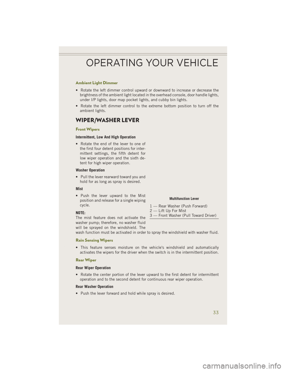
WIPER/WASHER LEVER
Front Wipers
Intermittent, Low And High Operation
• Rotate the end of the lever to one ofthe first four detent positions for inter-
mittent settings, the fifth detent for
low wiper operation and the sixth de-
tent for high wiper operation.
Washer Operation
• Pull the lever rearward toward you and hold for as long as spray is desired.
Mist
• Push the lever upward to the Mist position and release for a single wiping
cycle.
NOTE:
The mist feature does not activate the
washer pump; therefore, no washer fluid
will be sprayed on the windshield. The
wash function must be activated in order to spray the windshield with washer fluid.
Rain Sensing Wipers
• This feature senses moisture on the vehicle's windshield and automatically activates the wipers for the driver when the switch is in the intermittent position.
Rear Wiper
Rear Wiper Operation
• Rotate the center portion of the lever upward to the first detent for intermittentoperation and to the second detent for continuous rear wiper operation.
Rear Washer Operation
• Push the lever forward and hold while spray is desired.
Multifunction Lever
1 — Rear Washer (Push Forward)
2 — Lift Up For Mist
3 — Front Washer (Pull Toward Driver)
OPERATING YOUR VEHICLE
33
Page 47 of 204
Air Recirculation
• Use Recirculation for maximum A/C operation.
• For window defogging, turn the Recirculation button off.
• If the Recirculation button is pushed while in the AUTO mode, the indicator lightmay flash three times to indicate the cabin air is being controlled automatically.
Heated Mirrors
The mirrors are heated to melt frost or ice. This feature is activated whenever you turn
on the rear window defroster.
ELECTRIC PARK BRAKE
• Your vehicle is equipped with a newElectric Park Brake System (EPB) that
offers greater convenience.
• The parking brake switch is located in the center console.
• To apply the park brake manually, pull up on the switch momentarily. The
BRAKE warning lamp in the instru-
ment cluster and an indicator on the
switch will illuminate.
• To release the park brake manually, the ignition switch must be in RUN.
Then put your foot on the brake pedal
and push the park brake switch down
momentarily. Once the park brake is
fully disengaged, the BRAKE warning
lamp and the switch indicator will extinguish.
• The park brake can also be automatically released. With the engine running and the transmission in gear, release the brake pedal and depress the throttle pedal.
For safety reasons, your seatbelt must also be fastened.
• The new Auto Park Brake feature can be used to apply the park brake automati- cally every time you park the vehicle. Auto Park Brake can be enabled and disabled
in the Setting menu in UConnect
®.
• Safehold is a new feature that will automatically apply the park brake under certain conditions. The EPB monitors the status of the driver’s seat belt, driver’s
door and pedal positions to determine that you may have exited while the vehicle
is still capable of moving, and will then automatically apply the park brake to
prevent the vehicle from rolling.
• Refer to the Starting and Operating section of your vehicle’s Owner’s Manual for further details.
Electric Park Brake Switch
OPERATING YOUR VEHICLE
45