display JEEP CHEROKEE 2014 KL / 5.G User Guide
[x] Cancel search | Manufacturer: JEEP, Model Year: 2014, Model line: CHEROKEE, Model: JEEP CHEROKEE 2014 KL / 5.GPages: 204, PDF Size: 3.84 MB
Page 8 of 204
DRIVER COCKPIT
1. Driver Memory Seat pg. 25
2. Headlight Switch pg. 32
3. Liftgate Button
4. Electronic Vehicle Information Center (EVIC) Controls pg. 121
5. Turn Signal/Light Lever pg. 31
6. Tachometer pg. 8
7. Electronic Vehicle Information Center (EVIC) Display pg. 8
8. Speedometer pg. 9
9. Wiper/Washer Lever pg. 33
10. Your Vehicle’s Sound System pg. 54
CONTROLS AT A GLANCE
6
Page 10 of 204
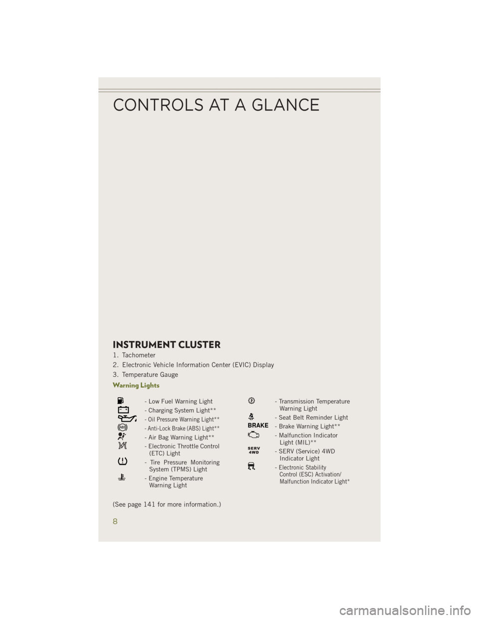
INSTRUMENT CLUSTER
1. Tachometer
2. Electronic Vehicle Information Center (EVIC) Display
3. Temperature Gauge
Warning Lights
- Low Fuel Warning Light
- Charging System Light**
- Oil Pressure Warning Light**
- Anti-Lock Brake (ABS) Light**
- Air Bag Warning Light**
- Electronic Throttle Control(ETC) Light
- Tire Pressure MonitoringSystem (TPMS) Light
- Engine TemperatureWarning Light
- Transmission TemperatureWarning Light
- Seat Belt Reminder Light
BRAKE- Brake Warning Light**
- Malfunction IndicatorLight (MIL)**
- SERV (Service) 4WDIndicator Light
-Electronic StabilityControl (ESC) Activation/
Malfunction Indicator Light*
(See page 141 for more information.)
CONTROLS AT A GLANCE
8
Page 27 of 204
FRONT SEATS
Power Seats
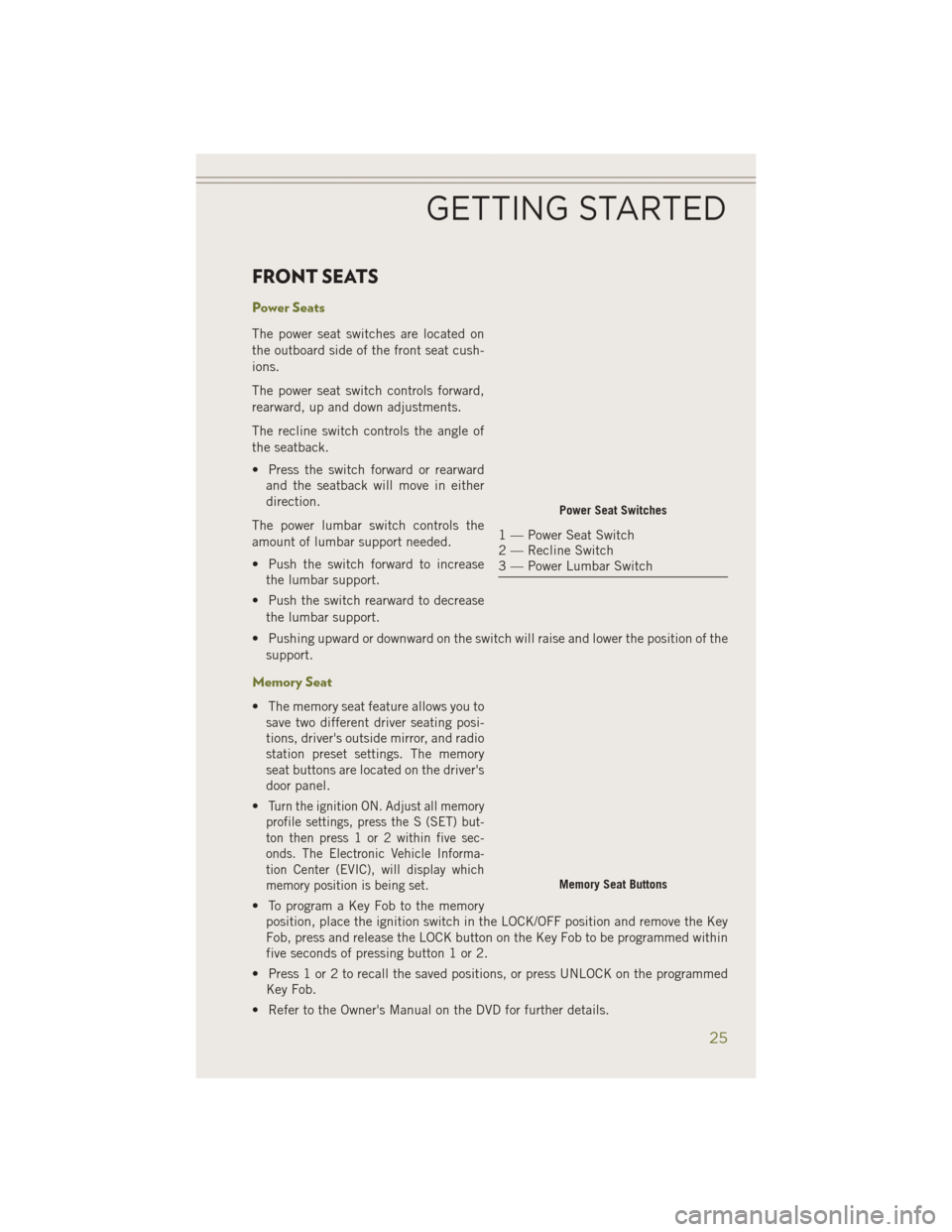
The power seat switches are located on
the outboard side of the front seat cush-
ions.
The power seat switch controls forward,
rearward, up and down adjustments.
The recline switch controls the angle of
the seatback.
• Press the switch forward or rearwardand the seatback will move in either
direction.
The power lumbar switch controls the
amount of lumbar support needed.
• Push the switch forward to increase the lumbar support.
• Push the switch rearward to decrease the lumbar support.
• Pushing upward or downward on the switch will raise and lower the position of the support.
Memory Seat
• The memory seat feature allows you tosave two different driver seating posi-
tions, driver's outside mirror, and radio
station preset settings. The memory
seat buttons are located on the driver's
door panel.
•
Turn the ignition ON. Adjust all memory
profile settings, press the S (SET) but-
ton then press 1 or 2 within five sec-
onds. The Electronic Vehicle Informa-
tion Center (EVIC), will display which
memory position is being set.
• To program a Key Fob to the memory position, place the ignition switch in the LOCK/OFF position and remove the Key
Fob, press and release the LOCK button on the Key Fob to be programmed within
five seconds of pressing button 1 or 2.
• Press 1 or 2 to recall the saved positions, or press UNLOCK on the programmed Key Fob.
• Refer to the Owner's Manual on the DVD for further details.
Power Seat Switches
1 — Power Seat Switch
2 — Recline Switch
3 — Power Lumbar Switch
Memory Seat Buttons
GETTING STARTED
25
Page 31 of 204
WARNING!
• Persons who are unable to feel pain to the skin because of advanced age,chronic illness, diabetes, spinal cord injury, medication, alcohol use, exhaus-
tion or other physical conditions must exercise care when using the seat heater.
It may cause burns even at low temperatures, especially if used for long periods
of time.
• Do not place anything on the seat that insulates against heat, such as a blanket
or cushion. This may cause the seat heater to overheat. Sitting in a seat that
has been overheated could cause serious burns due to the increased surface
temperature of the seat.
HEATED STEERING WHEEL
• The steering wheel contains a heatingelement that heats the steering wheel
to one temperature setting.
• To access the Heated Steering Wheel soft-key, touch the “Controls” soft-key
located on the Uconnect
®display.
• Touch the soft-key once to turn the heating element On. Press the soft-key
a second time to turn the heating ele-
ment Off.
• Once the heated steering wheel has been turned on, it will operate for up to
80 minutes before automatically shut-
ting off. The heated steering wheel can
shut off early or may not turn on when
the steering wheel is already warm.
WARNING!
• Persons who are unable to feel pain to the skin because of advanced age,
chronic illness, diabetes, spinal cord injury, medication, alcohol use, exhaus-
tion, or other physical conditions must exercise care when using the steering
wheel heater. It may cause burns even at low temperatures, especially if used
for long periods.
• Do not place anything on the steering wheel that insulates against heat, such
as a blanket or steering wheel covers of any type and material. This may cause
the steering wheel heater to overheat.
GETTING STARTED
29
Page 38 of 204
ADAPTIVE CRUISE CONTROL (ACC)
If your vehicle is equipped with adaptive
cruise control the controls operate ex-
actly the same as the normal (fixed
speed) speed control with one difference.
You can set a specified distance you
would like to maintain between you and
the vehicle in front of you.
If the ACC sensor detects a vehicle
ahead, ACC will apply limited braking or
acceleration automatically to maintain a
preset following distance, while match-
ing the speed of the vehicle ahead.
If the sensor does not detect a vehicle
ahead of you, ACC will maintain a fixed
set speed.
ACC ON/OFF
• Push and release the Adaptive Cruise Control (ACC) ON/OFF button.
ACC READY will appear on the instrument cluster to indicate the ACC is on.
• Push and release the Adaptive Cruise Control (ACC) ON/OFF button a second timeto turn the system off.
Adaptive Cruise Control (ACC) Off will appear on the instrument cluster to indicate
the ACC is off.
Distance Setting (ACC Only)
The specified following distance for ACC can be set by varying the distance setting
between four bars (longest), three bars (long), two bars (medium) and one bar (short).
Using this distance setting and the vehicle speed, ACC calculates and sets the
distance to the vehicle ahead. This distance setting displays in the EVIC.
• To increase the distance setting, press the Distance Setting—Increase button and release. Each time the button is pressed, the distance setting increases by one bar
(longer).
• To decrease the distance setting, press the Distance Setting—Decrease button and release. Each time the button is pressed, the distance setting decreases by
one bar (shorter).
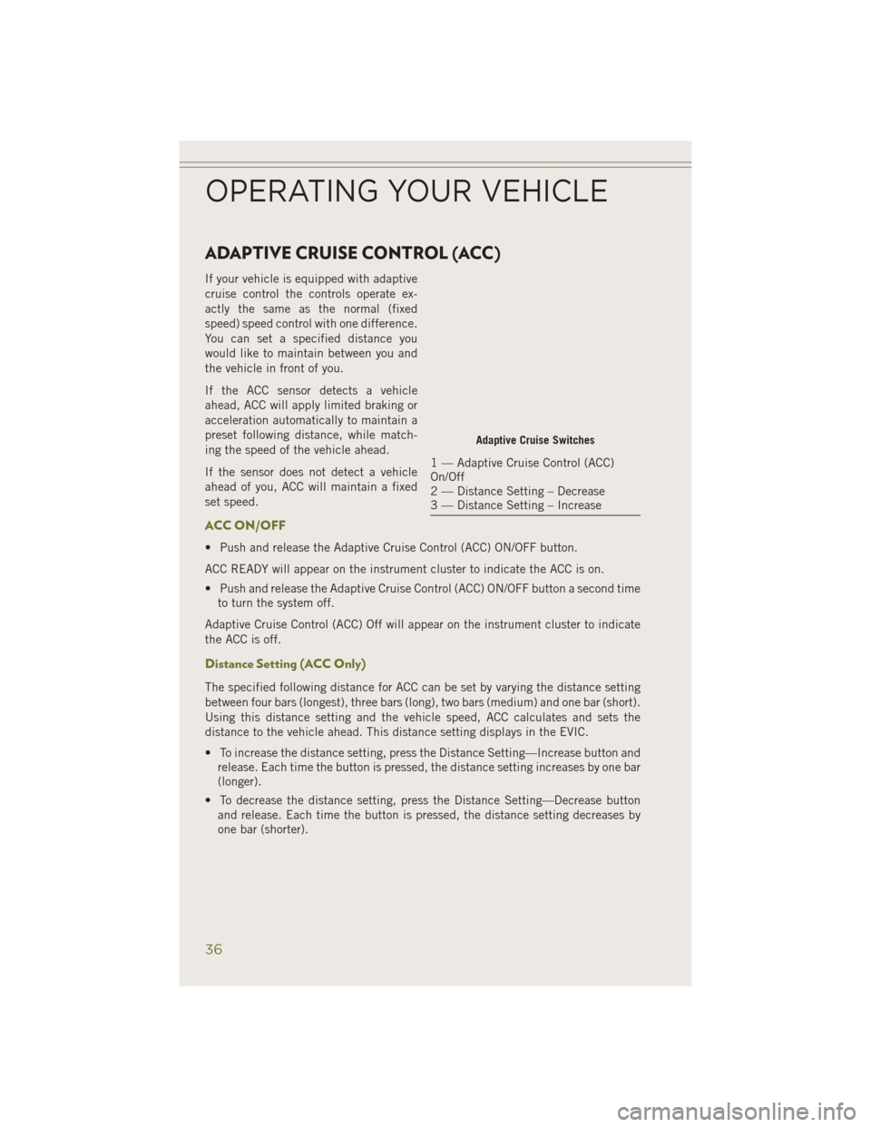
Adaptive Cruise Switches
1 — Adaptive Cruise Control (ACC)
On/Off
2 — Distance Setting – Decrease
3 — Distance Setting – Increase
OPERATING YOUR VEHICLE
36
Page 42 of 204
Far
The default status of FCW is the “Far” setting.
The far setting provides warnings for potential collisions more distant in front of the
vehicle, allowing the driver to have the most reaction time to avoid a collision.
This setting is designed to provide early warnings per NHTSA (National Highway
Traffic Safety Administration) recommendations.
More cautious drivers that do not mind frequent warnings may prefer this setting.
NOTE:
This setting gives you the most reaction time.
Near
Changing the FCW status to the “Near” setting, allows the system to warn you of a
potential frontal collision when you are much closer.
This setting provides less reaction time than the “Far” setting, which allows for a
more dynamic driving experience.
More dynamic or aggressive drivers that want to avoid frequent warnings may prefer
this setting.
Off
Changing the FCW status to “Off” prevents the system from warning you of a possible
collision with the vehicle in front of you.
Turning Active Braking ON Or OFF
The Active Braking feature has two settings and can be changed within the
Uconnect
®System Screen:
•On
• Off
Changing the Active Braking status to “Off” prevents the system from providing
limited autonomous braking, or additional brake support if the driver is not braking
adequately in the event of a potential frontal collision.
NOTE:
If FCW is set to “Off”, “FCW OFF” will be displayed in the EVIC.
Refer to the Owner's Manual on the DVD for further details.
WARNING!
Forward Collision Warning (FCW) is not intended to avoid a collision on its own, nor
can FCW detect every type of potential collision. The driver has the responsibility
to avoid a collision by controlling the vehicle via braking and steering. Failure to
follow this warning could lead to serious injury or death.
OPERATING YOUR VEHICLE
40
Page 48 of 204
PARKSENSE®
ParkSense® Front And Rear Park Assist
ParkSense®can be enabled and disabled by pressing the ParkSense®switch located
on the switch panel below the Uconnect®display.
The six ParkSense
®sensors, located in
the rear fascia/bumper, monitor the area
behind the vehicle that is within the sen-
sors’ field of view. The sensors can detect
obstacles from approximately 12 in
(30 cm) up to 79 in (200 cm) from the
rear fascia/bumper in the horizontal di-
rection, depending on the location, type
and orientation of the obstacle.
The six ParkSense
®sensors, located in
the front fascia/bumper, monitor the area
in front of the vehicle that is within the
sensors’ field of view. The sensors can
detect obstacles from approximately
12 in (30 cm) up to 47 in (120 cm) from
the front fascia/bumper in the horizontal
direction, depending on the location, type and orientation of the obstacle.
When an object is detected within 2 meters behind the rear bumper while the vehicle
is in REVERSE, a warning will display in the Electronic Vehicle Information Center
(EVIC). In addition a chime will sound (when Sound and Display is selected from the
Customer Programmable Features screen of the Uconnect
®System). As the vehicle
moves closer to the object, the chime rate will change from single 1/2 second tone
(for rear only), to slow (for rear only), to fast, to continuous.
Refer to your Owner's Manual on the DVD for further details.
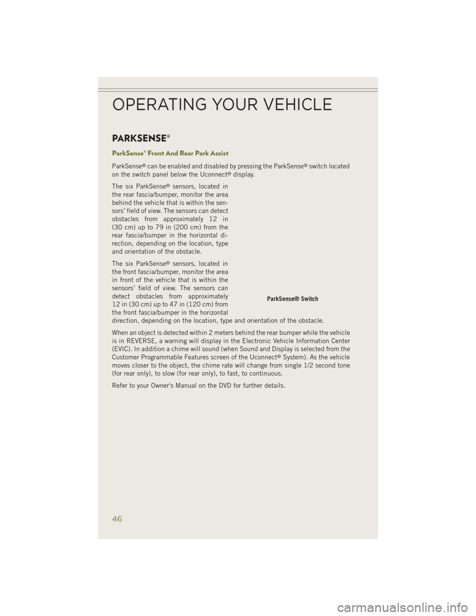
ParkSense® Switch
OPERATING YOUR VEHICLE
46
Page 49 of 204
ParkSense® Active Park Assist
The ParkSense®Active Park Assist system can be enabled and disabled with the
ParkSense®Active Park Assist switch, located on the switch panel below the
Uconnect®display.
The ParkSense
®Active Park Assist sys-
tem is intended to assist the driver during
parallel and perpendicular parking ma-
neuvers by identifying a proper parking
space, providing audible/visual instruc-
tions, and controlling the steering wheel.
The ParkSense
®Active Park Assist sys-
tem is defined as “semi-automatic”
since the driver maintains control of the
accelerator, shift lever and brakes. De-
pending on the driver’s parking maneuver
selection, the ParkSense
®Active Park
Assist system is capable of maneuvering
a vehicle into a parallel or a perpendicu-
lar parking space on either side (i.e.,
driver side or passenger side).
Refer to your Owner's Manual on the DVD for further details.
CAUTION!
• ParkSense®is only a parking aid and it is unable to recognize every obstacle,
including small obstacles. Parking curbs might be temporarily detected or not
detected at all. Obstacles located above or below the sensors will not be
detected when they are in close proximity.
• The vehicle must be driven slowly when using ParkSense
®in order to be able
to stop in time when an obstacle is detected. It is recommended that the driver
looks over his/her shoulder when using ParkSense
®.
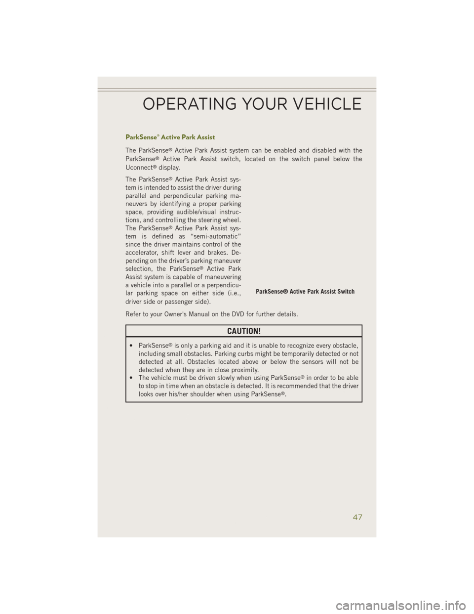
ParkSense® Active Park Assist Switch
OPERATING YOUR VEHICLE
47
Page 50 of 204
WARNING!
• Drivers must be careful when backing up even when using ParkSense®. Always
check carefully behind your vehicle, look behind you, and be sure to check for
pedestrians, animals, other vehicles, obstructions, and blind spots before
backing up. You are responsible for safety and must continue to pay attention
to your surroundings. Failure to do so can result in serious injury or death.
• Before using ParkSense
®, it is strongly recommended that the ball mount and
hitch ball assembly is disconnected from the vehicle when the vehicle is not
used for towing. Failure to do so can result in injury or damage to vehicles or
obstacles because the hitch ball will be much closer to the obstacle than the
rear fascia when the loudspeaker sounds the continuous tone. Also, the sensors
could detect the ball mount and hitch ball assembly, depending on its size and
shape, giving a false indication that an obstacle is behind the vehicle.
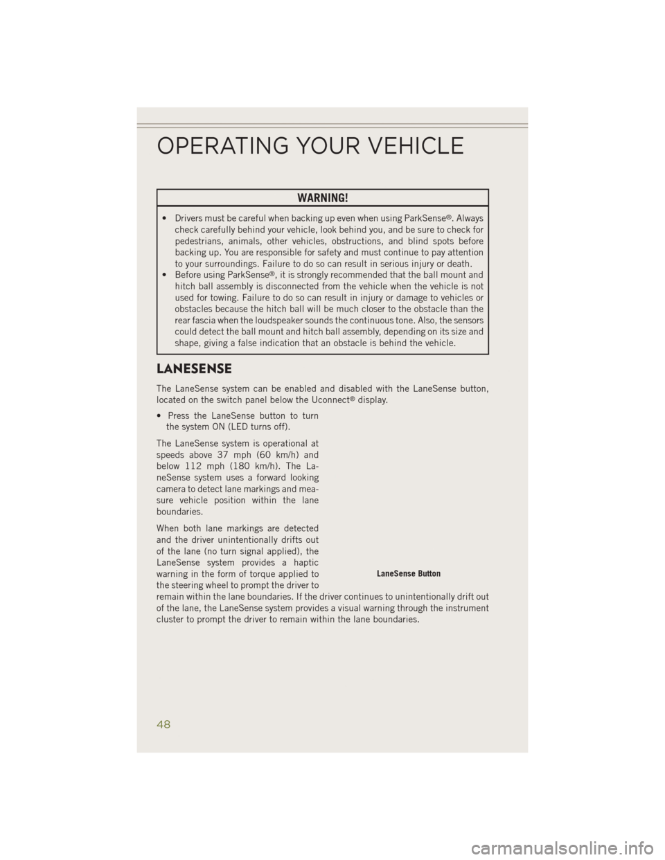
LANESENSE
The LaneSense system can be enabled and disabled with the LaneSense button,
located on the switch panel below the Uconnect®display.
• Press the LaneSense button to turn the system ON (LED turns off).
The LaneSense system is operational at
speeds above 37 mph (60 km/h) and
below 112 mph (180 km/h). The La-
neSense system uses a forward looking
camera to detect lane markings and mea-
sure vehicle position within the lane
boundaries.
When both lane markings are detected
and the driver unintentionally drifts out
of the lane (no turn signal applied), the
LaneSense system provides a haptic
warning in the form of torque applied to
the steering wheel to prompt the driver to
remain within the lane boundaries. If the driver continues to unintentionally drift out
of the lane, the LaneSense system provides a visual warning through the instrument
cluster to prompt the driver to remain within the lane boundaries.
LaneSense Button
OPERATING YOUR VEHICLE
48
Page 51 of 204
The driver may manually override the haptic warning by applying torque into the
steering wheel at any time.
When only a single lane marking is detected and the driver unintentionally drifts
across the lane marking (no turn signal applied), the LaneSense system provides a
visual warning through the instrument cluster to prompt the driver to remain within
the lane. When only a single lane marking is detected, a haptic (torque) warning will
not be provided.
Refer to your Owner's Manual on the DVD for further details.
NOTE:
When operating conditions have been met, the LaneSense system will monitor if the
driver’s hands are on the steering wheel and provides an audible warning to the driver
when the driver’s hands are not detected on the steering wheel. The system will
cancel if the driver does not return their hands to the wheel.
PARKVIEW® REAR BACK-UP CAMERA
You can see an on-screen image of the rear of your vehicle whenever the shift lever is
put into REVERSE. The ParkView®Rear Back-Up Camera image will be displayed on
the radio display screen, located on the center stack of the instrument panel.
If the radio display screen appears foggy, clean the camera lens located on the rear
of the vehicle above the rear license plate.
Refer to your Owner's Manual on the DVD for further details.
WARNING!
Drivers must be careful when backing up; even when using the ParkView®Rear
Back-Up Camera. Always check carefully behind your vehicle, and be sure to
check for pedestrians, animals, other vehicles, obstructions, or blind spots before
backing up. You must continue to pay attention while backing up. Failure to do so
can result in serious injury or death.
OPERATING YOUR VEHICLE
49