engine JEEP CHEROKEE 2015 KL / 5.G Owners Manual
[x] Cancel search | Manufacturer: JEEP, Model Year: 2015, Model line: CHEROKEE, Model: JEEP CHEROKEE 2015 KL / 5.GPages: 772, PDF Size: 18.21 MB
Page 645 of 772
CAUTION!
Failure to follow these procedures could result in
damage to the charging system of the booster vehicle
or the discharged vehicle.
Connecting The Jumper Cables
1. Connect the positive(+)end of the jumper cable to the
positive(+)post of the discharged vehicle.
2. Connect the opposite end of the positive(+)jumper
cable to the positive(+)post of the booster battery.
3. Connect the negative(-)end of the jumper cable to the
negative(-)post of the booster battery.
4. Connect the opposite end of the negative(-)jumper
cable to a good engine ground (exposed metal part of
the discharged vehicle’s engine) away from the battery
and the fuel injection system.
WARNING!
Do not connect the jumper cable to the negative (-)
post of the discharged battery. The resulting electri-
cal spark could cause the battery to explode and
could result in personal injury. Only use the specific
ground point, do not use any other exposed metal
parts.
5. Start the engine in the vehicle that has the booster
battery, let the engine idle a few minutes, and then
start the engine in the vehicle with the discharged
battery.
6
WHAT TO DO IN EMERGENCIES 643
Page 646 of 772
6. Once the engine is started, remove the jumper cables
in the reverse sequence:
Disconnecting The Jumper Cables
1. Disconnect the negative(-)end of the jumper cable
from the engine ground of the vehicle with the dis-
charged battery.
2. Disconnect the opposite end of the negative(-)jumper
cable from the negative(-)post of the booster battery.
3. Disconnect the positive(+)end of the jumper cable
from the positive(+)post of the booster battery.
4. Disconnect the opposite end of the positive(+)jumper
cable from the positive(+)post of the vehicle with the
discharged battery.
If frequent jump-starting is required to start your vehicle
you should have the battery and charging system in-
spected at your authorized dealer.
CAUTION!
Accessories plugged into the vehicle power outlets
draw power from the vehicle’s battery, even when not
in use (i.e., cellular phones, etc.). Eventually, if
plugged in long enough without engine operation,
the vehicle’s battery will discharge sufficiently to
degrade battery life and/or prevent the engine from
starting.
FREEING A STUCK VEHICLE
If your vehicle becomes stuck in mud, sand or snow, it
can often be moved using a rocking motion. Turn the
steering wheel right and left to clear the area around the
front wheels. Press and hold the lock button on the shift
lever. Then shift back and forth between DRIVE and
REVERSE, while gently pressing the accelerator.
644 WHAT TO DO IN EMERGENCIES
Page 647 of 772
NOTE:Shifts between DRIVE and REVERSE can only be
achieved at wheel speeds of 5 mph (8 km/h) or less.
Whenever the transmission remains in NEUTRAL for
more than two seconds, you must press the brake pedal
to engage DRIVE or REVERSE.
Use the least amount of accelerator pedal pressure that
will maintain the rocking motion without spinning the
wheels or racing the engine.
CAUTION!
•Racing the engine or spinning the wheels may lead
to transmission overheating and failure. Allow the
engine to idle with the transmission in NEUTRAL
for at least one minute after every five rocking-
motion cycles. This will minimize overheating and
reduce the risk of transmission failure during pro-
longed efforts to free a stuck vehicle.
(Continued)
CAUTION!(Continued)
•When “rocking” a stuck vehicle by shifting be-
tween DRIVE and REVERSE, do not spin the
wheels faster than 15 mph (24 km/h), or drivetrain
damage may result.
•Revving the engine or spinning the wheels too fast
may lead to transmission overheating and failure.
It can also damage the tires. Do not spin the wheels
above 30 mph (48 km/h) while in gear (no trans-
mission shifting occurring).
NOTE:Press the “ESC Off” switch (if necessary), to place
the Electronic Stability Control (ESC) system in “Partial
Off” mode, before rocking the vehicle. Refer to “Elec-
tronic Brake Control” in “Starting And Operating” for
further information. Once the vehicle has been freed,
press the#ESC Off#switch again to restore “ESC On”
mode.
6
WHAT TO DO IN EMERGENCIES 645
Page 649 of 772
Using Recovery Strap
1. Review all warnings and instructions first.
2. Position the recovery vehicle.
3. Connect the recovery strap.
4. Add a recovery damper or blanket.
5. Clear the danger zone.
6. Safely and slowly start pulling.
7. Disconnect the recovery strap after both vehicle are
secure and parked.
SHIFT LEVER OVERRIDE
If a malfunction occurs and the shift lever cannot be
moved out of the PARK position, you can use the
following procedure to temporarily move the shift lever:
1. Turn the engine OFF.
2. Apply the parking brake.
3. Using a screwdriver or similar tool, carefully separate
the shifter bezel and boot assembly from the center
console bezel.
4. Press and maintain firm pressure on the brake pedal.
5. Insert a small screwdriver or similar tool down into
the shift lever override access hole (at the right front
corner of the shift lever assembly), and push and hold
the override release lever down.
6. Move the shift lever to the NEUTRAL position.
7. The vehicle may then be started in NEUTRAL.
8. Reinstall the shift lever boot.
6
WHAT TO DO IN EMERGENCIES 647
Page 655 of 772
MAINTAINING YOUR VEHICLE
CONTENTS
!ENGINE COMPARTMENT — 2.4L..........655
!ENGINE COMPARTMENT — 3.2L..........656
!ONBOARD DIAGNOSTIC SYSTEM — OBD II . .657
▫Loose Fuel Filler Cap Message............657
!EMISSIONS INSPECTION AND MAINTENANCE
PROGRAMS..........................658
!REPLACEMENT PARTS..................659
!DEALER SERVICE......................659
!MAINTENANCE PROCEDURES...........660
▫Engine Oil..........................661
▫Engine Oil Filter......................664
▫Engine Air Cleaner Filter................664
▫Accessory Drive Belt Inspection...........668
▫Maintenance-Free Battery...............669
▫Air Conditioner Maintenance.............670
▫Body Lubrication.....................675
▫Windshield Wiper Blades...............676
▫Adding Washer Fluid..................683
▫Exhaust System......................684
▫Cooling System......................686
7
Page 656 of 772
▫Brake System........................692
▫Automatic Transmission................694
▫Sky Slider™ Top Care..................696
▫Appearance Care And Protection From
Corrosion...........................698
!FUSES..............................705
▫Power Distribution Center...............706
▫Interior Fuses........................719
!VEHICLE STORAGE....................720
!REPLACEMENT BULBS.................721
!BULB REPLACEMENT..................722
▫Low Beam And High Beam Headlamps.....722
▫Front Turn Signals And Front Side
Marker Lamps.......................724
▫Front Fog Lamp......................724
▫Front Fog Lamp (Trailhawk).............725
▫Bodyside Mounted Back-up Lamp.........725
▫Liftgate Mounted Back-up Lamp..........726
▫License Plate Lamp....................726
!FLUID CAPACITIES....................727
!FLUIDS, LUBRICANTS AND GENUINE PARTS . .728
▫Engine.............................728
▫Chassis............................730
654 MAINTAINING YOUR VEHICLE
Page 657 of 772
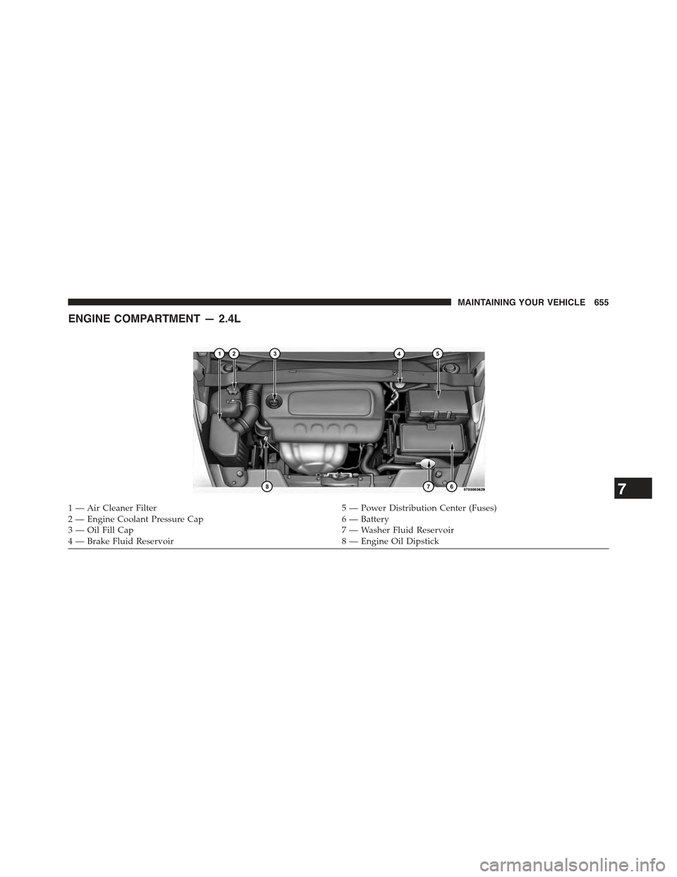
ENGINE COMPARTMENT — 2.4L
1 — Air Cleaner Filter5 — Power Distribution Center (Fuses)2 — Engine Coolant Pressure Cap6 — Battery3 — Oil Fill Cap7 — Washer Fluid Reservoir4 — Brake Fluid Reservoir8 — Engine Oil Dipstick
7
MAINTAINING YOUR VEHICLE 655
Page 658 of 772
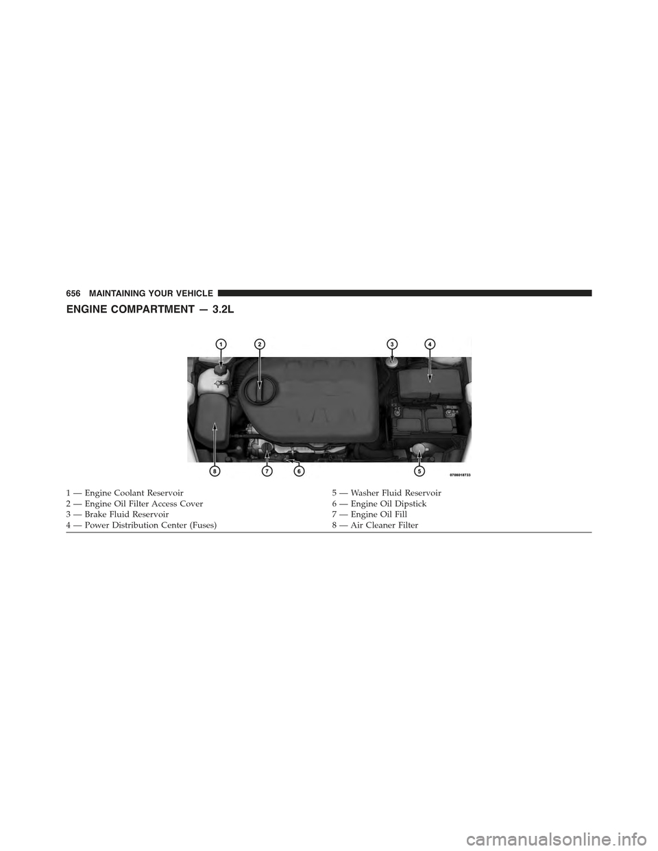
ENGINE COMPARTMENT — 3.2L
1 — Engine Coolant Reservoir5 — Washer Fluid Reservoir2 — Engine Oil Filter Access Cover6 — Engine Oil Dipstick3 — Brake Fluid Reservoir7 — Engine Oil Fill4 — Power Distribution Center (Fuses)8 — Air Cleaner Filter
656 MAINTAINING YOUR VEHICLE
Page 659 of 772
ONBOARD DIAGNOSTIC SYSTEM — OBD II
Your vehicle is equipped with a sophisticated onboard
diagnostic system called OBD II. This system monitors
the performance of the emissions, engine, and automatic
transmission control systems. When these systems are
operating properly, your vehicle will provide excellent
performance and fuel economy, as well as engine emis-
sions well within current government regulations.
If any of these systems require service, the OBD II system
will turn on the “Malfunction Indicator Light (MIL).” It
will also store diagnostic codes and other information to
assist your service technician in making repairs. Al-
though your vehicle will usually be drivable and not
need towing, see your authorized dealer for service as
soon as possible.
CAUTION!
•Prolonged driving with the MIL on could cause
further damage to the emission control system. It
could also affect fuel economy and driveability.
The vehicle must be serviced before any emissions
tests can be performed.
•If the MIL is flashing while the engine is running,
severe catalytic converter damage and power loss
will soon occur. Immediate service is required.
Loose Fuel Filler Cap Message
If the vehicle diagnostic system determines that the fuel
filler cap is loose, improperly installed, or damaged, a
“CHECK GASCAP” message will be displayed in the
Electronic Vehicle Information Center (EVIC) or Driver
Information Display (DID). Refer to “Electronic Vehicle
Information (EVIC) or#Driver Information Display
(DID)” in “Understanding Your Instrument Panel” for
7
MAINTAINING YOUR VEHICLE 657
Page 660 of 772
further information. Tighten the fuel filler cap until a
“clicking” sound is heard. This is an indication that the
fuel filler cap is properly tightened. Refer to “Onboard
Diagnostic System” in “Maintaining Your Vehicle” for
further information.
EMISSIONS INSPECTION AND MAINTENANCE
PROGRAMS
In some localities, it may be a legal requirement to pass
an inspection of your vehicle’s emissions control system.
Failure to pass could prevent vehicle registration.
For states that require an Inspection and Mainte-
nance (I/M), this check verifies the “Malfunction
Indicator Light (MIL)” is functioning and is not
on when the engine is running, and that the OBD II
system is ready for testing.
Normally, the OBD II system will be ready. The OBD II
system maynotbe ready if your vehicle was recently
serviced, recently had a dead battery or a battery replace-
ment. If the OBD II system should be determined not
ready for the I/M test, your vehicle may fail the test.
Your vehicle has a simple ignition actuated test, which
you can use prior to going to the test station. To check if
your vehicle’s OBD II system is ready, you must do the
following:
1. Cycle the ignition switch to the ON position, but do
not crank or start the engine.
NOTE:If you crank or start the engine, you will have to
start this test over.
2. As soon as you cycle the ignition switch to the ON
position, you will see the MIL symbol come on as part
of a normal bulb check.
658 MAINTAINING YOUR VEHICLE