brake JEEP CHEROKEE 2017 KL / 5.G Owners Manual
[x] Cancel search | Manufacturer: JEEP, Model Year: 2017, Model line: CHEROKEE, Model: JEEP CHEROKEE 2017 KL / 5.GPages: 615, PDF Size: 5.72 MB
Page 412 of 615
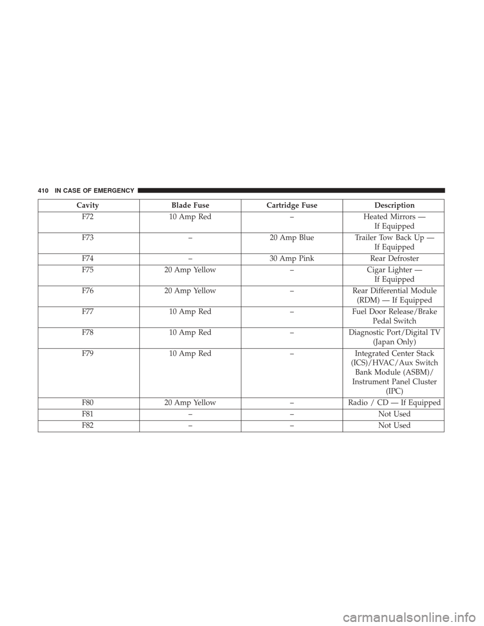
CavityBlade Fuse Cartridge Fuse Description
F72 10 Amp Red –Heated Mirrors —
If Equipped
F73 –20 Amp Blue Trailer Tow Back Up —
If Equipped
F74 –30 Amp Pink Rear Defroster
F75 20 Amp Yellow –Cigar Lighter —
If Equipped
F76 20 Amp Yellow –Rear Differential Module
(RDM) — If Equipped
F77 10 Amp Red –Fuel Door Release/Brake
Pedal Switch
F78 10 Amp Red –Diagnostic Port/Digital TV
(Japan Only)
F79 10 Amp Red –Integrated Center Stack
(ICS)/HVAC/Aux Switch Bank Module (ASBM)/
Instrument Panel Cluster (IPC)
F80 20 Amp Yellow –Radio / CD — If Equipped
F81 ––Not Used
F82 ––Not Used
410 IN CASE OF EMERGENCY
Page 413 of 615
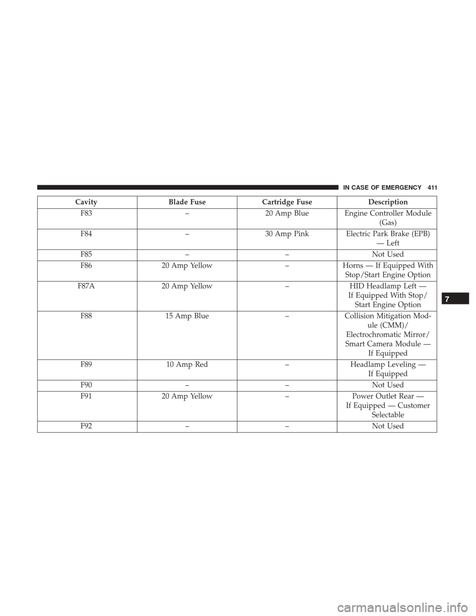
CavityBlade Fuse Cartridge Fuse Description
F83 –20 Amp Blue Engine Controller Module
(Gas)
F84 –30 Amp Pink Electric Park Brake (EPB)
— Left
F85 ––Not Used
F86 20 Amp Yellow –Horns — If Equipped With
Stop/Start Engine Option
F87A 20 Amp Yellow –HID Headlamp Left —
If Equipped With Stop/ Start Engine Option
F88 15 Amp Blue –Collision Mitigation Mod-
ule (CMM)/
Electrochromatic Mirror/
Smart Camera Module — If Equipped
F89 10 Amp Red –Headlamp Leveling —
If Equipped
F90 ––Not Used
F91 20 Amp Yellow –Power Outlet Rear —
If Equipped — Customer Selectable
F92 ––Not Used
7
IN CASE OF EMERGENCY 411
Page 414 of 615
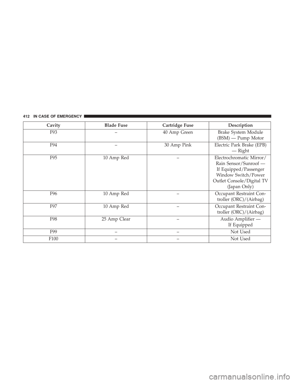
CavityBlade Fuse Cartridge Fuse Description
F93 –40 Amp Green Brake System Module
(BSM) — Pump Motor
F94 –30 Amp Pink Electric Park Brake (EPB)
— Right
F95 10 Amp Red –Electrochromatic Mirror/
Rain Sensor/Sunroof —If Equipped/Passenger
Window Switch/Power
Outlet Console/Digital TV (Japan Only)
F96 10 Amp Red –Occupant Restraint Con-
troller (ORC)/(Airbag)
F97 10 Amp Red –Occupant Restraint Con-
troller (ORC)/(Airbag)
F98 25 Amp Clear –Audio Amplifier —
If Equipped
F99 ––Not Used
F100 ––Not Used
412 IN CASE OF EMERGENCY
Page 418 of 615
WARNING!
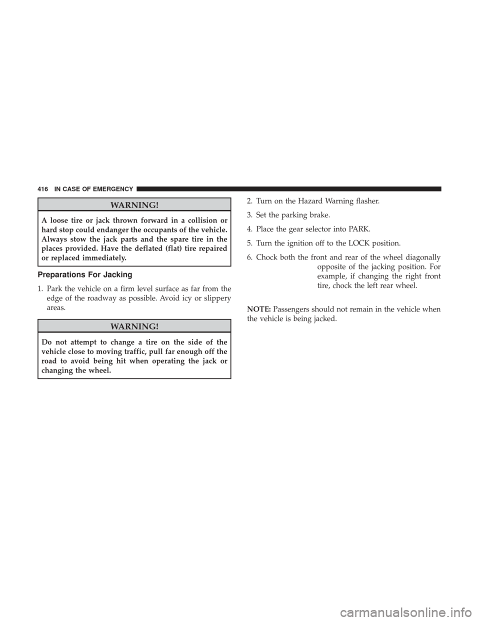
A loose tire or jack thrown forward in a collision or
hard stop could endanger the occupants of the vehicle.
Always stow the jack parts and the spare tire in the
places provided. Have the deflated (flat) tire repaired
or replaced immediately.
Preparations For Jacking
1. Park the vehicle on a firm level surface as far from theedge of the roadway as possible. Avoid icy or slippery
areas.
WARNING!
Do not attempt to change a tire on the side of the
vehicle close to moving traffic, pull far enough off the
road to avoid being hit when operating the jack or
changing the wheel. 2. Turn on the Hazard Warning flasher.
3. Set the parking brake.
4. Place the gear selector into PARK.
5. Turn the ignition off to the LOCK position.
6. Chock both the front and rear of the wheel diagonally
opposite of the jacking position. For
example, if changing the right front
tire, chock the left rear wheel.
NOTE: Passengers should not remain in the vehicle when
the vehicle is being jacked.
416 IN CASE OF EMERGENCY
Page 419 of 615
Jacking Instructions
WARNING!
Carefully follow these tire changing warnings to help
prevent personal injury or damage to your vehicle:
•
Always park on a firm, level surface as far from the
edge of the roadway as possible before raising the
vehicle.
• Turn on the Hazard Warning flasher.
•
Chock the wheel diagonally opposite the wheel to be
raised.
•Set the parking brake firmly and set the transmission
in PARK.
•Never start or run the engine with the vehicle on a
jack.
•Do not let anyone sit in the vehicle when it is on a jack.
•Do not get under the vehicle when it is on a jack. If you
need to get under a raised vehicle, take it to a service
center where it can be raised on a lift.
•Only use the jack in the positions indicated and for
lifting this vehicle during a tire change.
•If working on or near a roadway, be extremely careful
of motor traffic.
(Continued)
WARNING! (Continued)
•To assure that spare tires, flat or inflated, are securely
stowed, spares must be stowed with the valve stem
facing the ground.
Jack Warning Label
7
IN CASE OF EMERGENCY 417
Page 425 of 615
5. Lower the jack until it is free. Remove the wheel chocks.Reassemble the lug wrench to the jack assembly and
stow it in the spare tire area. Secure the assembly using
the means provided. Release the parking brake before
driving the vehicle.
6. After 25 miles (40 km) check the wheel bolt torque with a torque wrench to ensure that all wheel bolts are
properly seated against the wheel.
TIRE SERVICE KIT — IF EQUIPPED
Small punctures up to 1/4 inch (6 mm) in the tire tread can
be sealed with Tire Service Kit. Foreign objects (e.g., screws
or nails) should not be removed from the tire. Tire Service
Kit can be used in outside temperatures down to approxi-
mately -4°F (-20°C).
This kit will provide a temporary tire seal, allowing you to
drive your vehicle up to 100 miles (160 km) with a
maximum speed of 55 mph (90 km/h).
Tire Service Kit Storage
The Tire Service Kit is stowed under the load floor behind
the rear seat.
1. Open the liftgate.
2. Lift the access cover using the load floor handle.
Load Floor Handle
7
IN CASE OF EMERGENCY 423
Page 429 of 615
Sealing A Tire With Tire Service Kit
(A) Whenever You Stop To Use Tire Service Kit:
1. Pull over to a safe location and turn on the vehicle’sHazard Warning flashers.
2. Verify that the valve stem (on the wheel with the deflated tire) is in a position that is near to the ground.
This will allow the Tire Service Kit Hoses (6) and (7) to
reach the valve stem and keep the Tire Service Kit flat on
the ground. This will provide the best positioning of the
kit when injecting the sealant into the deflated tire and
running the air pump. Move the vehicle as necessary to
place the valve stem in this position before proceeding.
3. Place the transmission in PARK (auto transmission) or in Gear (manual transmission) and place the ignition in the
OFF position.
4. Set the parking brake.
(B) Setting Up To Use Tire Service Kit:
1. Push in the Mode Select Knob (5) and turn to the Sealant Mode position.
2. Uncoil the Sealant Hose (6) and then remove the cap from the fitting at the end of the hose.
3. Place the Tire Service Kit flat on the ground next to the deflated tire.
4. Remove the cap from the valve stem and then screw the fitting at the end of the Sealant Hose (6) onto the valve
stem.
5. Uncoil the Power Plug (8) and insert the plug into the vehicle’s 12 Volt power outlet.
NOTE: Do not remove foreign objects (e.g., screws or
nails) from the tire.
7
IN CASE OF EMERGENCY 427
Page 430 of 615
(C) Injecting Tire Service Kit Sealant Into The
Deflated Tire:
•Always start the engine before turning ON the Tire
Service Kit.
NOTE: Manual transmission vehicles must have the park-
ing brake engaged and the gear selector in NEUTRAL.
• After pushing the Power Button (4), the sealant (white
fluid) will flow from the Sealant Bottle (1) through the
Sealant Hose (6) and into the tire.
NOTE: Sealant may leak out through the puncture in the
tire. If the sealant (white fluid) does not flow within0–10
seconds through the Sealant Hose (6):
1. Push the Power Button (4) to turn Off the Tire Service
Kit. Disconnect the Sealant Hose (6) from the valve stem.
Make sure the valve stem is free of debris. Reconnect the
Sealant Hose (6) to the valve stem. Check that the Mode
Select Knob (5) is in the Sealant Mode position and not
Air Mode. Push the Power Button (4) to turn On the Tire
Service Kit.
2. Connect the Power Plug (8) to a different 12 Volt power outlet in your vehicle or another vehicle, if available.
Make sure the engine is running before turning ON the
Tire Service Kit.
3. The Sealant Bottle (1) may be empty due to previous use. Call for assistance.
NOTE: If the Mode Select Knob (5) is on Air Mode and the
pump is operating, air will dispense from the Air Pump
Hose (7) only, not the Sealant Hose (6).
428 IN CASE OF EMERGENCY
Page 435 of 615
1. Set the parking brake, shift the automatic transmissioninto PARK and turn the ignition to LOCK.
2. Turn off the heater, radio, and all unnecessary electrical accessories.
3. If using another vehicle to jump-start the battery, park the vehicle within the jumper cables reach, set the
parking brake and make sure the ignition is OFF.
WARNING!
Do not allow vehicles to touch each other as this could
establish a ground connection and personal injury
could result.
Jump Starting Procedure
WARNING!
Failure to follow this jump-starting procedure could
result in personal injury or property damage due to
battery explosion.
CAUTION!
Failure to follow these procedures could result in
damage to the charging system of the booster vehicle
or the discharged vehicle.
Connecting The Jumper Cables
1. Connect the positive (+)end of the jumper cable to the
positive (+)post of the discharged vehicle.
2. Connect the opposite end of the positive (+)jumper
cable to the positive (+)post of the booster battery.
3. Connect the negative (-)end of the jumper cable to the
negative (-)post of the booster battery.
4. Connect the opposite end of the negative (-)jumper
cable to a good engine ground (exposed metal part of
the discharged vehicle’s engine) away from the battery
and the fuel injection system.
7
IN CASE OF EMERGENCY 433
Page 439 of 615
GEAR SELECTOR OVERRIDE
If a malfunction occurs and the gear selector cannot be
moved out of the PARK position, you can use the following
procedure to temporarily move the gear selector:
1. Turn the engine OFF.
2. Apply the parking brake.
3. Using a screwdriver or similar tool, carefully separatethe shifter bezel and boot assembly from the center
console.
4. Press and maintain firm pressure on the brake pedal.
5. Insert a small screwdriver or similar tool down into the gear selector override access hole (at the right front
corner of the gear selector assembly), and push and hold
the override release lever down.
6. Move the gear selector to the NEUTRAL position.
7. The vehicle may then be started in NEUTRAL.
8. Reinstall the gear selector boot.
FREEING A STUCK VEHICLE
If your vehicle becomes stuck in mud, sand or snow, it can
often be moved using a rocking motion. Turn the steering
wheel right and left to clear the area around the front
wheels. Push and hold the lock button on the gear selector.
Then shift back and forth between DRIVE and REVERSE,
while gently pressing the accelerator.
NOTE: Shifts between DRIVE and REVERSE can only be
achieved at wheel speeds of 5 mph (8 km/h) or less.
Whenever the transmission remains in NEUTRAL for more
than two seconds, you must push the brake pedal to
engage DRIVE or REVERSE.
Use the least amount of accelerator pedal pressure that will
maintain the rocking motion without spinning the wheels
or racing the engine.
7
IN CASE OF EMERGENCY 437