brake light JEEP CHEROKEE 2017 KL / 5.G Owner's Manual
[x] Cancel search | Manufacturer: JEEP, Model Year: 2017, Model line: CHEROKEE, Model: JEEP CHEROKEE 2017 KL / 5.GPages: 615, PDF Size: 5.72 MB
Page 175 of 615
Traction Control System (TCS)
This system monitors the amount of wheel spin of each of
the driven wheels. If wheel spin is detected, the TCS may
apply brake pressure to the spinning wheel(s) and/or
reduce engine power to provide enhanced acceleration and
stability. A feature of the TCS, Brake Limited Differential
(BLD), functions similar to a limited slip differential and
controls the wheel spin across a driven axle. If one wheel
on a driven axle is spinning faster than the other, the
system will apply the brake of the spinning wheel. This
will allow more engine torque to be applied to the wheel
that is not spinning. BLD may remain enabled even if TCS
and ESC are in a reduced mode.
Electronic Stability Control (ESC)
This system enhances directional control and stability of
the vehicle under various driving conditions. ESC corrects
for oversteering or understeering of the vehicle by apply-
ing the brake of the appropriate wheel(s) to assist in
counteracting the oversteer or understeer condition. En-
gine power may also be reduced to help the vehicle
maintain the desired path.ESC uses sensors in the vehicle to determine the vehicle
path intended by the driver and compares it to the actual
path of the vehicle. When the actual path does not match
the intended path, ESC applies the brake of the appropriate
wheel to assist in counteracting the oversteer or understeer
condition.
•
Oversteer - when the vehicle is turning more than
appropriate for the steering wheel position.
• Understeer - when the vehicle is turning less than
appropriate for the steering wheel position.
The “ESC Activation/Malfunction Indicator Light” located
in the instrument cluster will start to flash as soon as the ESC
system becomes active. The “ESC Activation/Malfunction
Indicator Light” also flashes when the TCS is active. If the
“ESC Activation/Malfunction Indicator Light” begins to
flash during acceleration, ease up on the accelerator and
apply as little throttle as possible. Be sure to adapt your
speed and driving to the prevailing road conditions.
5
SAFETY 173
Page 179 of 615
NOTE:
•The “ESC Activation/Malfunction Indicator Light” and
the “ESC OFF Indicator Light” come on momentarily
each time the ignition is turned ON.
• Each time the ignition is turned ON, the ESC system will
be on even if it was turned off previously.
• The ESC system will make buzzing or clicking sounds
when it is active. This is normal; the sounds will stop
when ESC becomes inactive following the maneuver
that caused the ESC activation.
The “ESC OFF Indicator Light” indicates the
customer has elected to have the Electronic Sta-
bility Control (ESC) in a reduced mode.
Electronic Roll Mitigation (ERM)
This system anticipates the potential for wheel lift by
monitoring the driver ’s steering wheel input and the speed
of the vehicle. When ERM determines that the rate of
change of the steering wheel angle and vehicle’s speed are
sufficient to potentially cause wheel lift, it then applies the
appropriate brake and may also reduce engine power to
lessen the chance that wheel lift will occur. ERM can only reduce the chance of wheel lift occurring during severe or
evasive driving maneuvers; it cannot prevent wheel lift
due to other factors, such as road conditions, leaving the
roadway, or striking objects or other vehicles.
NOTE:
ERM is disabled anytime the ESC is in “Full Off”
mode (if equipped). Refer to “Electronic Stability Control
(ESC)” in this section for a complete explanation of the
available ESC modes.
WARNING!
Many factors, such as vehicle loading, road conditions
and driving conditions, influence the chance that
wheel lift or rollover may occur. ERM cannot prevent
all wheel lift or roll overs, especially those that involve
leaving the roadway or striking objects or other ve-
hicles. The capabilities of an ERM-equipped vehicle
must never be exploited in a reckless or dangerous
manner which could jeopardize the user’s safety or the
safety of others.
5
SAFETY 177
Page 180 of 615
Trailer Sway Control (TSC)
TSC uses sensors in the vehicle to recognize an excessively
swaying trailer and will take the appropriate actions to
attempt to stop the sway. TSC will become active automati-
cally once an excessively swaying trailer is recognized.
Note that TSC cannot stop all trailers from swaying.
Always use caution when towing a trailer and follow the
trailer tongue weight recommendations. Refer to “Trailer
Towing” in “Starting And Operating” for further informa-
tion. When TSC is functioning, the “ESC Activation/
Malfunction Indicator Light” will flash, the engine power
may be reduced and you may feel the brakes being applied
to individual wheels to attempt to stop the trailer from
swaying. TSC is disabled when the ESC system is in the
“Partial Off” or “Full Off” modes.
WARNING!
If TSC activates while driving, slow the vehicle down,
stop at the nearest safe location, and adjust the trailer
load to eliminate trailer sway.
Ready Alert Braking (RAB)
Ready Alert Braking may reduce the time required to reach
full braking during emergency braking situations. It antici-
pates when an emergency braking situation may occur by
monitoring how fast the throttle is released by the driver.
The EBC will prepare the brake system for a panic stop.
Rain Brake Support (RBS)
Rain Brake Support may improve braking performance in
wet conditions. It will periodically apply a small amount of
brake pressure to remove any water buildup on the front
brake rotors. It functions when the windshield wipers are
in LO or HI speed. When Rain Brake Support is active,
there is no notification to the driver and no driver interac-
tion is required.
Dynamic Steering Torque (DST)
Dynamic Steering Torque is a feature of the ESC and EPS
modules that provides torque at the steering wheel for
certain driving conditions in which the ESC module is
detecting vehicle instability. The torque that the steering
wheel receives is only meant to help the driver realize
optimal steering behavior in order to reach/maintain vehicle
stability. The only notification the driver receives that the
feature is active is the torque applied to the steering wheel.
178 SAFETY
Page 255 of 615
The best protection against carbon monoxide entry into the
vehicle body is a properly maintained engine exhaust
system.
Whenever a change is noticed in the sound of the exhaust
system, when exhaust fumes can be detected inside the
vehicle, or when the underside or rear of the vehicle is
damaged, have a competent mechanic inspect the complete
exhaust system and adjacent body areas for broken, dam-
aged, deteriorated, or mispositioned parts. Open seams or
loose connections could permit exhaust fumes to seep into
the passenger compartment. In addition, inspect the ex-
haust system each time the vehicle is raised for lubrication
or oil change. Replace as required.
Safety Checks You Should Make Inside The Vehicle
Seat Belts
Inspect the seat belt system periodically, checking for cuts,
frays, and loose parts. Damaged parts must be replaced
immediately. Do not disassemble or modify the system.
Front seat belt assemblies must be replaced after a collision.
Rear seat belt assemblies must be replaced after a collision
if they have been damaged (i.e., bent retractor, torn web-
bing, etc.). If there is any question regarding seat belt or
retractor condition, replace the seat belt.
Air Bag Warning Light
The Air Bag warning lightwill turn on for four to
eight seconds as a bulb check when the ignition switch
is first turned to ON/RUN. If the light is either not on
during starting, stays on, or turns on while driving,
have the system inspected at an authorized dealer as
soon as possible. This light will illuminate with a single
chime when a fault with the Air Bag Warning Light has
been detected, it will stay on until the fault is cleared. If
the light comes on intermittently or remains on while
driving, have an authorized dealer service the vehicle
immediately. Refer to “Occupant Restraint Systems” in
“Safety” for further information.
Defroster
Check operation by selecting the defrost mode and place
the blower control on high speed. You should be able to
feel the air directed against the windshield. See your
authorized dealer for service if your defroster is inoper-
able.
Floor Mat Safety Information
Always use floor mats designed to fit your vehicle. Only
use a floor mat that does not interfere with the operation of
the accelerator, brake or clutch pedals. Only use a floor mat
5
SAFETY 253
Page 256 of 615
that is securely attached using the floor mat fasteners so it
cannot slip out of position and interfere with the accelera-
tor, brake or clutch pedals or impair safe operation of your
vehicle in other ways.
WARNING!
An improperly attached, damaged, folded, or stacked
floor mat, or damaged floor mat fasteners may cause
your floor mat to interfere with the accelerator, brake,
or clutch pedals and cause a loss of vehicle control. To
prevent SERIOUS INJURY or DEATH:
•ALWAYS securely attach
your floor mat using
the floor mat fasteners. DO NOT install your floor
mat upside down or turn your floor mat over.
Lightly pull to confirm mat is secured using the
floor mat fasteners on a regular basis.
• ALWAYS REMOVE THE EXISTING FLOOR MAT
FROM THE VEHICLE
before installing any
other floor mat. NEVER install or stack an addi-
tional floor mat on top of an existing floor mat.
(Continued)
WARNING! (Continued)
•ONLY install floor mats designed to fit your vehicle.
NEVER install a floor mat that cannot be properly
attached and secured to your vehicle. If a floor mat
needs to be replaced, only use a FCA approved floor
mat for the specific make, model, and year of your
vehicle.
•
ONLY use the driver ’s side floor mat on the driver ’s
side floor area. To check for interference, with the
vehicle properly parked with the engine off, fully
depress the accelerator, the brake, and the clutch pedal
(if present) to check for interference. If your floor mat
interferes with the operation of any pedal, or is not
secure to the floor, remove the floor mat from the
vehicle and place the floor mat in your trunk.
• ONLY use the passenger ’s side floor mat on the
passenger ’s side floor area.
• ALWAYS make sure objects cannot fall or slide into
the driver ’s side floor area when the vehicle is
moving. Objects can become trapped under accelera-
tor, brake, or clutch pedals and could cause a loss of
vehicle control.
(Continued)
254 SAFETY
Page 257 of 615
WARNING!(Continued)
•NEVER place any objects under the floor mat (e.g.,
towels, keys, etc.). These objects could change the
position of the floor mat and may cause interference
with the accelerator, brake, or clutch pedals.
• If the vehicle carpet has been removed and re-
installed, always properly attach carpet to the floor
and check the floor mat fasteners are secure to the
vehicle carpet. Fully depress each pedal to check for
interference with the accelerator, brake, or clutch
pedals then re-install the floor mats.
• It is recommended to only use mild soap and water
to clean your floor mats. After cleaning, always check
your floor mat has been properly installed and is
secured to your vehicle using the floor mat fasteners
by lightly pulling mat.
Periodic Safety Checks You Should Make Outside
The Vehicle
Tires
Examine tires for excessive tread wear and uneven wear
patterns. Check for stones, nails, glass, or other objects
lodged in the tread or sidewall. Inspect the tread for cuts
and cracks. Inspect sidewalls for cuts, cracks, and bulges.
Check the wheel nuts for tightness. Check the tires (includ-
ing spare) for proper cold inflation pressure.
Lights
Have someone observe the operation of brake lights and
exterior lights while you work the controls. Check turn signal
and high beam indicator lights on the instrument panel.
Door Latches
Check for proper closing, latching, and locking.
Fluid Leaks
Check area under vehicle after overnight parking for fuel,
engine coolant, oil, or other fluid leaks. Also, if gasoline
fumes are detected or if fuel, power steering fluid (if
equipped), or brake fluid leaks are suspected. The cause
should be located and corrected immediately.
5
SAFETY 255
Page 267 of 615
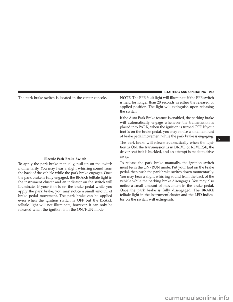
The park brake switch is located in the center console.
To apply the park brake manually, pull up on the switch
momentarily. You may hear a slight whirring sound from
the back of the vehicle while the park brake engages. Once
the park brake is fully engaged, the BRAKE telltale light in
the instrument cluster and an indicator on the switch will
illuminate. If your foot is on the brake pedal while you
apply the park brake, you may notice a small amount of
brake pedal movement. The park brake can be applied
even when the ignition switch is OFF but the BRAKE
telltale light will not illuminate, however, it can only be
released when the ignition is in the ON/RUN mode.NOTE:
The EPB fault light will illuminate if the EPB switch
is held for longer than 20 seconds in either the released or
applied position. The light will extinguish upon releasing
the switch.
If the Auto Park Brake feature is enabled, the parking brake
will automatically engage whenever the transmission is
placed into PARK, when the ignition is turned OFF. If your
foot is on the brake pedal, you may notice a small amount
of brake pedal movement while the park brake is engaging.
The park brake will release automatically when the igni-
tion is ON, the transmission is in DRIVE or REVERSE, the
driver seat belt is buckled, and an attempt is made to drive
away.
To release the park brake manually, the ignition switch
must be in the ON/RUN mode. Put your foot on the brake
pedal, then push the park brake switch down momentarily.
You may hear a slight whirring sound from the back of the
vehicle while the parking brake disengages. You may also
notice a small amount of movement in the brake pedal.
Once the park brake is fully disengaged, The BRAKE
telltale light in the instrument cluster and the LED indica-
tor on the switch will extinguish.
Electric Park Brake Switch
6
STARTING AND OPERATING 265
Page 268 of 615
NOTE:When parking on a hill, it is important to turn the
front wheels toward the curb on a downhill grade and
away from the curb on an uphill grade. Apply the park
brake before placing the gear selector in PARK, otherwise
the load on the transmission locking mechanism may make
it difficult to move the gear selector out of PARK. The
parking brake should always be applied whenever the
driver is not in the vehicle.
WARNING!
• Never use the PARK position as a substitute for the
parking brake. Always apply the parking brake fully
when parked to guard against vehicle movement and
possible injury or damage.
• When leaving the vehicle, always remove the key fob
from the ignition and lock your vehicle.
• Never leave children alone in a vehicle, or with
access to an unlocked vehicle. Allowing children to
be in a vehicle unattended is dangerous for a number
of reasons. A child or others could be seriously or
fatally injured. Children should be warned not to
touch the parking brake, brake pedal or the gear
selector.
(Continued)
WARNING! (Continued)
•Do not leave the key fob in or near the vehicle, or in
a location accessible to children, and do not leave a
vehicle equipped with Keyless Enter-N-Go in the
ACC or ON/RUN mode. A child could operate power
windows, other controls, or move the vehicle.
• Be sure the parking brake is fully disengaged before
driving; failure to do so can lead to brake failure and
a collision.
• Always fully apply the parking brake when leaving
your vehicle, or it may roll and cause damage or
injury. Also be certain to leave the transmission in
PARK. Failure to do so may allow the vehicle to roll
and cause damage or injury.
CAUTION!
If the Brake System Warning Light remains on with the
parking brake released, a brake system malfunction is
indicated. Have the brake system serviced by an au-
thorized dealer immediately.
266 STARTING AND OPERATING
Page 269 of 615
If exceptional circumstances should make it necessary to
engage the park brake while the vehicle is in motion,
maintain upward pressure on the electric park brake
switch for as long as engagement is desired. The BRAKE
telltale light will illuminate, and a continuous chime will
sound. The rear stop lamps will also be illuminated auto-
matically while the vehicle remains in motion.
To disengage the park brake while the vehicle is in motion,
release the switch. If the vehicle is brought to a complete
stop using the parking brake, when the vehicle reaches
approximately 3 mph, (5 km/h) the parking brake will
remain engaged.
WARNING!
Driving the vehicle with the parking brake engaged, or
repeated use of the parking brake to slow the vehicle
may cause serious damage to the brake system. Be sure
the parking brake is fully disengaged before driving;
failure to do so can lead to brake failure and a collision.
In the unlikely event of a malfunction of the Electric Park
Brake system, a yellow EPB fault light will illuminate. This
may be accompanied by the BRAKE telltale light flashing. In this event, urgent service of the electric park brake
system is required. Do not rely on the parking brake to
hold the vehicle stationary.
Auto Park Brake
The electric park brake can be programmed to be applied
automatically whenever the vehicle is at a standstill and
the automatic transmission is placed in PARK, whenever
the ignition is turned “OFF”. Auto Park Brake is enabled
and disabled by customer selection through the customer
programmable features section of the Uconnect Settings.
Any single auto park brake application can be bypassed by
pushing the EPB switch to the release position while the
transmission is placed in PARK.
SafeHold
SafeHold is a safety feature of the Electric Park Brake
System that will engage the park brake automatically if the
vehicle is left unsecured while the ignition is in RUN.
For automatic transmissions, the park brake will automati-
cally engage if all of the following conditions are met:
•
The vehicle is at a standstill.
• There is no attempt to depress the brake pedal or
accelerator pedal.
6
STARTING AND OPERATING 267
Page 282 of 615
Shift Positions
For additional information on the appropriate use of each
4WD system mode position, see the information below:
NEUTRAL
This range disengages the driveline from the powertrain. It
is to be used for flat towing behind another vehicle. Refer
to “Recreational Towing” in “Starting And Operating” for
further information.
WARNING!
You or others could be injured or killed if you leave the
vehicle unattended with the power transfer unit in the
NEUTRAL (N) position without first fully engaging
the parking brake. The NEUTRAL (N) position disen-
gages both the front and rear driveshafts from the
powertrain and will allow the vehicle to roll, even if
the transmission is in PARK. The parking brake
should always be applied when the driver is not in the
vehicle.
4WD LOW
This range is for low speed four-wheel drive. It provides an
additional gear reduction which allows for increased
torque to be delivered to both the front and rear wheels
while providing maximum pulling power for loose, slip-
pery road surfaces only. Do not exceed 25 mph (40 km/h).
NOTE:Refer to “Selec-Terrain – If Equipped” for further
information on the various positions and their intended
usages.
Shifting Procedures
Shifting Into 4X4 LOW
With the vehicle at speeds of 0 to 3 mph (0 to 5 km/h), the
ignition in the ON mode and the engine running, shift the
transmission into NEUTRAL, and push the “4WD LOW”
button once. The “4WD LOW” indicator light in the
instrument cluster will begin to flash and remain on solid
when the shift is complete.
280 STARTING AND OPERATING