lights JEEP CHEROKEE 2017 KL / 5.G Owner's Guide
[x] Cancel search | Manufacturer: JEEP, Model Year: 2017, Model line: CHEROKEE, Model: JEEP CHEROKEE 2017 KL / 5.GPages: 615, PDF Size: 5.72 MB
Page 235 of 615
Enhanced Accident Response System
In the event of an impact, if the communication network
remains intact, and the power remains intact, depending
on the nature of the event, the ORC will determine whether
to have the Enhanced Accident Response System perform
the following functions:
•Cut off fuel to the engine.
• Flash hazard lights as long as the battery has power or
until the hazard light button is pressed. The hazard
lights can be deactivated by pressing the hazard light
button.
• Turn on the interior lights, which remain on as long as
the battery has power.
• Unlock the power door locks.
Enhanced Accident Response System Reset
Procedure
In order to reset the Enhanced Accident Response System
functions after an event, the ignition switch must be
changed from ignition START or ON/RUN to ignition OFF.
Carefully check the vehicle for fuel leaks in the engine compartment and on the ground near the engine compart-
ment and fuel tank before resetting the system and starting
the engine.
Maintaining Your Air Bag System
WARNING!
•
Modifications to any part of the air bag system could
cause it to fail when you need it. You could be
injured if the air bag system is not there to protect
you. Do not modify the components or wiring, in-
cluding adding any kind of badges or stickers to the
steering wheel hub trim cover or the upper right side
of the instrument panel. Do not modify the front
bumper, vehicle body structure, or add aftermarket
side steps or running boards.
• It is dangerous to try to repair any part of the air bag
system yourself. Be sure to tell anyone who works on
your vehicle that it has an air bag system.
• Do not attempt to modify any part of your air bag
system. The air bag may inflate accidentally or may
not function properly if modifications are made.
Take your vehicle to an authorized dealer for any air
bag system service. If your seat, including your trim
(Continued)
5
SAFETY 233
Page 257 of 615
WARNING!(Continued)
•NEVER place any objects under the floor mat (e.g.,
towels, keys, etc.). These objects could change the
position of the floor mat and may cause interference
with the accelerator, brake, or clutch pedals.
• If the vehicle carpet has been removed and re-
installed, always properly attach carpet to the floor
and check the floor mat fasteners are secure to the
vehicle carpet. Fully depress each pedal to check for
interference with the accelerator, brake, or clutch
pedals then re-install the floor mats.
• It is recommended to only use mild soap and water
to clean your floor mats. After cleaning, always check
your floor mat has been properly installed and is
secured to your vehicle using the floor mat fasteners
by lightly pulling mat.
Periodic Safety Checks You Should Make Outside
The Vehicle
Tires
Examine tires for excessive tread wear and uneven wear
patterns. Check for stones, nails, glass, or other objects
lodged in the tread or sidewall. Inspect the tread for cuts
and cracks. Inspect sidewalls for cuts, cracks, and bulges.
Check the wheel nuts for tightness. Check the tires (includ-
ing spare) for proper cold inflation pressure.
Lights
Have someone observe the operation of brake lights and
exterior lights while you work the controls. Check turn signal
and high beam indicator lights on the instrument panel.
Door Latches
Check for proper closing, latching, and locking.
Fluid Leaks
Check area under vehicle after overnight parking for fuel,
engine coolant, oil, or other fluid leaks. Also, if gasoline
fumes are detected or if fuel, power steering fluid (if
equipped), or brake fluid leaks are suspected. The cause
should be located and corrected immediately.
5
SAFETY 255
Page 286 of 615
NOTE:
•It may also be necessary to drive slowly steering back
and forth to complete engagement and disengagement
of the E-Locker.
• When engaging Rear E-Locker, the indicator lights in the
instrument cluster and on the REAR LOCK button will
begin to flash. When the shift is complete the REAR
LOCK indicator lights will remain on.
• When disengaging Rear E-Locker, the indicator lights in
the instrument cluster and on the REAR LOCK button
will begin to flash. When the shift is complete the REAR
LOCK indicator lights will remain off.
•
Shifting into or out of Rear E-Locker is possible with the
vehicle completely stopped; however, difficulty may occur
due to the mating clutch teeth not being properly aligned.
Several attempts may be required for clutch teeth align-
ment and shift completion to occur. The preferred method
is for the vehicle to be rolling, below 15 MPH (24 km/h),
while including right and left steering maneuvers to allow
for the clutch teeth to align.
• The Rear E-Locker System must be disengaged prior to
taking the vehicle out of 4WD LOW range. If 4WD LOW
shift conditions/interlocks are not met, a message will flash from the instrument cluster display with instruc-
tions on how to complete the requested shift.
SELEC-TERRAIN
Description
Selec-Terrain combines the capabilities of the vehicle con-
trol systems, along with driver input, to provide the best
performance for all terrains.
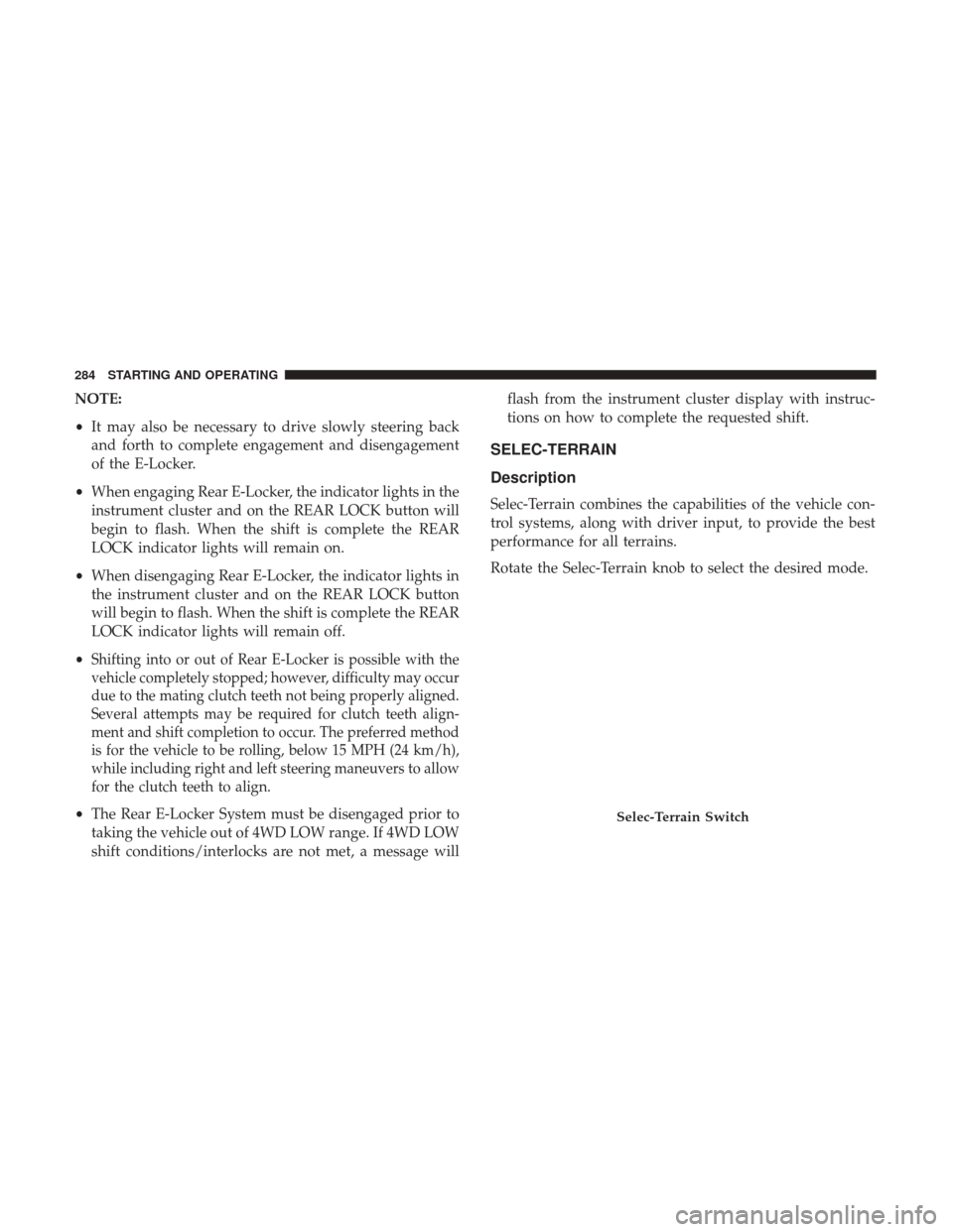
Rotate the Selec-Terrain knob to select the desired mode.
Selec-Terrain Switch
284 STARTING AND OPERATING
Page 304 of 615
To increase the distance setting, push the Distance Setting
— Increase button and release. Each time the button is
pushed, the distance setting increases by one bar (longer).
To decrease the distance setting, push the Distance Setting
— Decrease button and release. Each time the button is
pushed, the distance setting decreases by one bar (shorter).
If there is no vehicle ahead, the vehicle will maintain the set
speed. If a slower moving vehicle is detected in the same
lane, the instrument cluster display will show the “Sensed
Vehicle Indicator” icon, and the system will adjust the
vehicle speed automatically to maintain the distance set-
ting, regardless of the set speed.
The vehicle will then maintain the set distance until:
•The vehicle ahead accelerates to a speed above the set
speed.
• The vehicle ahead moves out of your lane or view of the
sensor.
• The distance setting is changed.
• The system disengages. (Refer to the information on
ACC Activation). The maximum braking applied by ACC is limited; how-
ever, the driver can always apply the brakes manually, if
necessary.
NOTE:
The brake lights will illuminate whenever the ACC
system applies the brakes.
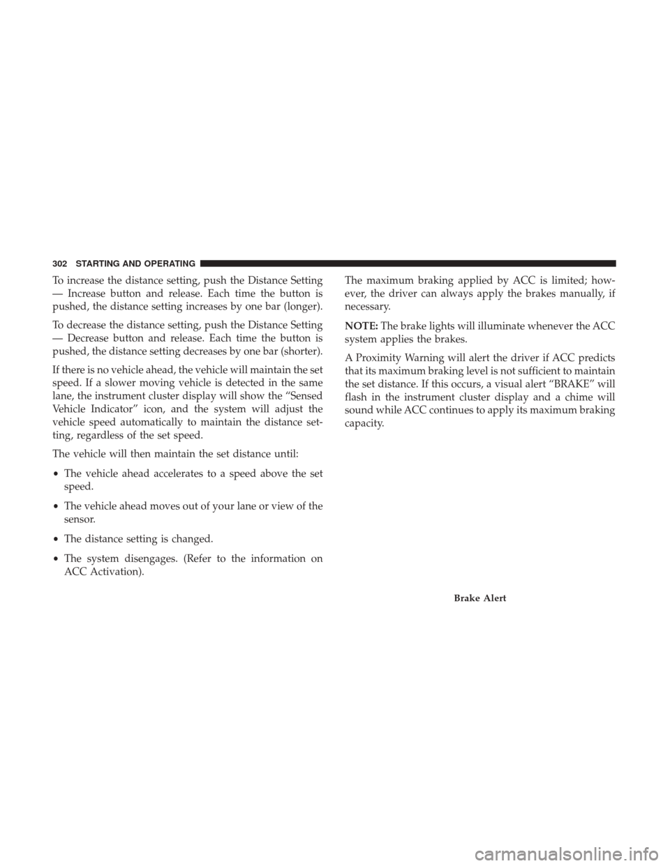
A Proximity Warning will alert the driver if ACC predicts
that its maximum braking level is not sufficient to maintain
the set distance. If this occurs, a visual alert “BRAKE” will
flash in the instrument cluster display and a chime will
sound while ACC continues to apply its maximum braking
capacity.
Brake Alert
302 STARTING AND OPERATING
Page 378 of 615
Towing Requirements — Trailer Lights And Wiring
Whenever you pull a trailer, regardless of the trailer size,
stoplights and turn signals on the trailer are required for
motoring safety.
The Trailer Tow Package may include a four- and seven-pin
wiring harness. Use a factory approved trailer harness and
connector.
NOTE:Do not cut or splice wiring into the vehicles wiring
harness.
The electrical connections are all complete to the vehicle
but you must mate the harness to a trailer connector. Refer
to the following illustrations.
Four-Pin Connector
1 — Female Pins 4 — Park
2 — Male Pin 5 — Left Stop/Turn
3 — Ground 6 — Right Stop/Turn
376 STARTING AND OPERATING
Page 385 of 615
7. After the shift is completed and the NEUTRAL (N) lightstays on, release the NEUTRAL (N) button.
8. Start the engine.
9. Release the parking brake.
10. Shift the transmission into REVERSE.
11. Release the brake pedal for five seconds and ensure that there is no vehicle movement.
12. Shift the transmission to NEUTRAL. 13. Apply the parking brake.
14. Shift the transmission into PARK, turn the engine OFF,
and remove the key fob.
15. Attach the vehicle to the tow vehicle using a suitable tow bar.
16. Turn the ignition to the ON/RUN mode, but do not start the engine.
17. Press and hold the brake pedal.
18. Release the parking brake.
19. Turn the ignition OFF, remove the key fob, and release the brake pedal.
NOTE:
• Steps 1 through 5 are requirements that must be met
before pushing the NEUTRAL (N) button, and must
continue to be met until the shift has been completed. If
any of these requirements are not met before pushing
the NEUTRAL (N) button or are no longer met during
the shift, then the NEUTRAL (N) indicator light will
flash continuously until all requirements are met or until
the NEUTRAL (N) button is released.
Neutral Switch
6
STARTING AND OPERATING 383
Page 386 of 615
•The ignition must be in the ON/RUN mode for a shift to
take place and for the position indicator lights to be
operable. If the ignition is not in the ON/RUN mode, the
shift will not take place and no position indicator lights
will be on or flashing.
• A flashing NEUTRAL (N) position indicator light indi-
cates that shift requirements have not been met.
Shifting Out Of NEUTRAL (N)
Use the following procedure to prepare your vehicle for
normal usage.
1. Bring the vehicle to a complete stop, leaving it con- nected to the tow vehicle.
2. Apply the parking brake.
3. Turn the ignition to the ON/RUN mode, but do not start the engine.
4. Press and hold the brake pedal.
5. Shift the transmission into NEUTRAL.
6. Using a ballpoint pen or similar object, push and hold the recessed power transfer unit NEUTRAL (N) button
(located by the selector switch) for one second. 7. When the NEUTRAL (N) indicator light turns off,
release the NEUTRAL (N) button.
8. After the NEUTRAL (N) button has been released, the power transfer unit will shift to the position indicated
by the selector switch.
NOTE: When shifting the power transfer unit out of
NEUTRAL (N), the engine should remain OFF to avoid
gear clash.
9. Shift the transmission into PARK.
Neutral Switch
384 STARTING AND OPERATING
Page 387 of 615
10. Release the brake pedal.
11. Disconnect vehicle from the tow vehicle.
12. Start the engine.
13. Press and hold the brake pedal.
14. Release the parking brake.
15. Shift the transmission into DRIVE, release the brakepedal, and check that the vehicle operates normally.
16. Re-enable the Auto Park Brake feature, if desired.
NOTE:
• Steps 1 through 5 are requirements that must be met
before pushing the NEUTRAL (N) button, and must
continue to be met until the shift has been completed. If
any of these requirements are not met before pushing
the NEUTRAL (N) button or are no longer met during
the shift, the NEUTRAL (N) indicator light will flash
continuously until all requirements are met or until the
NEUTRAL (N) button is released.
• The ignition must be in the ON/RUN mode for a shift to
take place and for the position indicator lights to be operable. If the ignition is not in the ON/RUN mode, the
shift will not take place and no position indicator lights
will be on or flashing.
• A flashing NEUTRAL (N) position indicator light indi-
cates that shift requirements have not been met.
DRIVING TIPS
On-Road Driving Tips
Utility vehicles have higher ground clearance and a nar-
rower track to make them capable of performing in a wide
variety of off-road applications. Specific design character-
istics give them a higher center of gravity than conven-
tional passenger cars.
An advantage of the higher ground clearance is a better
view of the road, allowing you to anticipate problems.
They are not designed for cornering at the same speeds as
conventional passenger cars any more than low-slung
sports cars are designed to perform satisfactorily in off-
road conditions. Avoid sharp turns or abrupt maneuvers.
As with other vehicles of this type, failure to operate this
vehicle correctly may result in loss of control or vehicle
rollover.6
STARTING AND OPERATING 385
Page 400 of 615
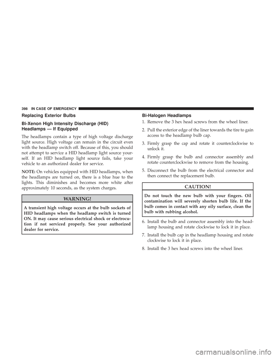
Replacing Exterior Bulbs
Bi-Xenon High Intensity Discharge (HID)
Headlamps — If Equipped
The headlamps contain a type of high voltage discharge
light source. High voltage can remain in the circuit even
with the headlamp switch off. Because of this, you should
not attempt to service a HID headlamp light source your-
self. If an HID headlamp light source fails, take your
vehicle to an authorized dealer for service.
NOTE:On vehicles equipped with HID headlamps, when
the headlamps are turned on, there is a blue hue to the
lights. This diminishes and becomes more white after
approximately 10 seconds, as the system charges.
WARNING!
A transient high voltage occurs at the bulb sockets of
HID headlamps when the headlamp switch is turned
ON. It may cause serious electrical shock or electrocu-
tion if not serviced properly. See your authorized
dealer for service.
Bi-Halogen Headlamps
1. Remove the 3 hex head screws from the wheel liner.
2. Pull the exterior edge of the liner towards the tire to gain access to the headlamp bulb cap.
3.
Firmly grasp the cap and rotate it counterclockwise to
unlock it.
4. Firmly grasp the bulb and connector assembly and rotate counterclockwise to remove from the housing.
5. Disconnect the bulb from the electrical connector and then connect the replacement bulb.
CAUTION!
Do not touch the new bulb with your fingers. Oil
contamination will severely shorten bulb life. If the
bulb comes in contact with any oily surface, clean the
bulb with rubbing alcohol.
6. Install the bulb and connector assembly into the head- lamp housing and rotate clockwise to lock it in place.
7. Install the bulb cap in the headlamp housing and rotate clockwise to lock it in place.
8. Install the 3 hex head screws into the wheel liner.
398 IN CASE OF EMERGENCY
Page 409 of 615
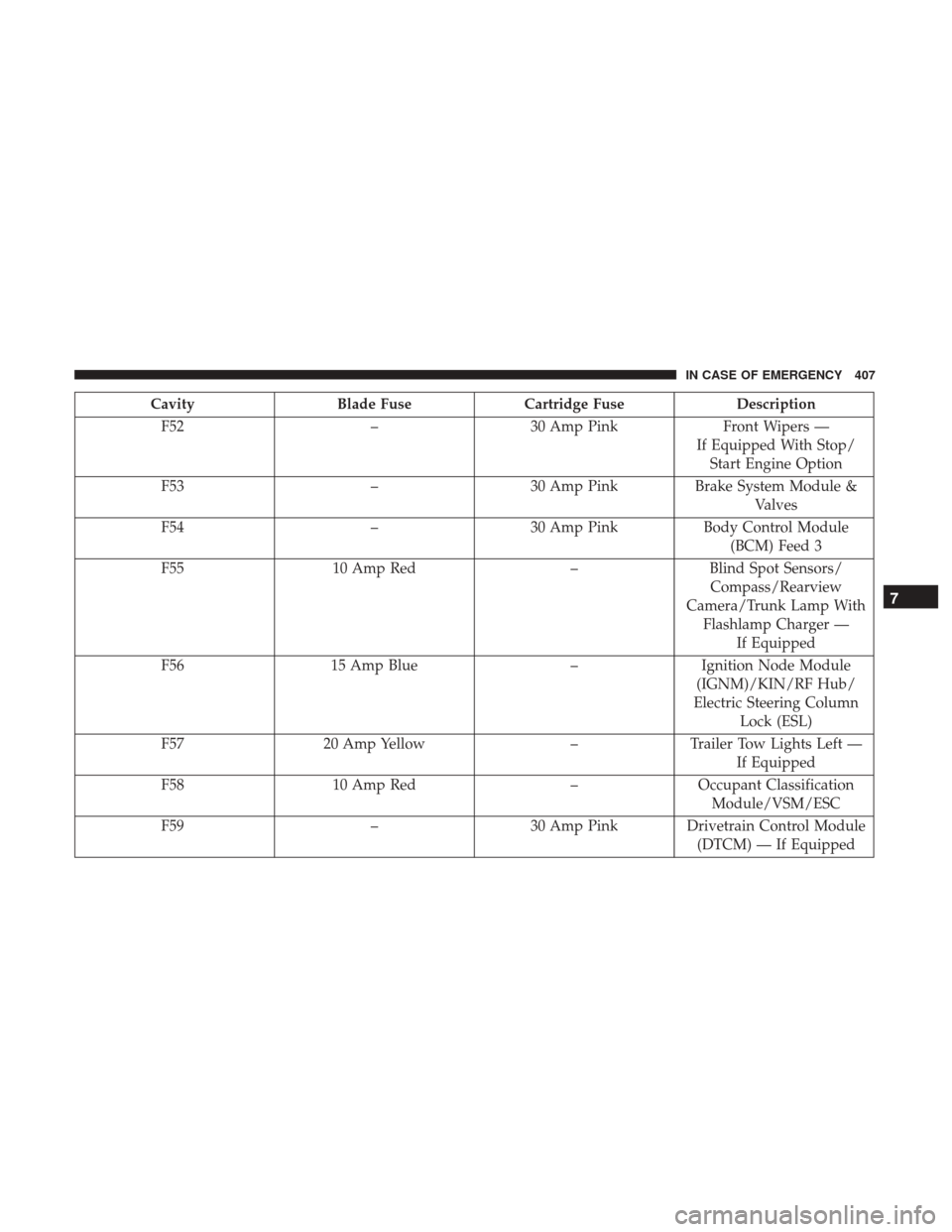
CavityBlade Fuse Cartridge Fuse Description
F52 –30 Amp Pink Front Wipers —
If Equipped With Stop/ Start Engine Option
F53 –30 Amp Pink Brake System Module &
Valves
F54 –30 Amp Pink Body Control Module
(BCM) Feed 3
F55 10 Amp Red –Blind Spot Sensors/
Compass/Rearview
Camera/Trunk Lamp With Flashlamp Charger — If Equipped
F56 15 Amp Blue –Ignition Node Module
(IGNM)/KIN/RF Hub/
Electric Steering Column Lock (ESL)
F57 20 Amp Yellow –Trailer Tow Lights Left —
If Equipped
F58 10 Amp Red –Occupant Classification
Module/VSM/ESC
F59 –30 Amp Pink Drivetrain Control Module
(DTCM) — If Equipped
7
IN CASE OF EMERGENCY 407