service JEEP CHEROKEE 2017 KL / 5.G Repair Manual
[x] Cancel search | Manufacturer: JEEP, Model Year: 2017, Model line: CHEROKEE, Model: JEEP CHEROKEE 2017 KL / 5.GPages: 615, PDF Size: 5.72 MB
Page 396 of 615
WARNING!(Continued)
•The 9-1-1 Call system is embedded into the vehicle’s
electrical system. Do not add aftermarket electrical
equipment to the vehicle’s electrical system. This
may prevent your vehicle from sending a signal to
initiate an emergency call. To avoid interference that
can cause the 9-1-1 Call system to fail, never add
aftermarket equipment (e.g., two-way mobile radio,
CB radio, data recorder, etc.) to your vehicle’s electri-
cal system or modify the antennas on your vehicle. IF
YOUR VEHICLE LOSES BATTERY POWER FOR
ANY REASON (INCLUDING DURING OR AFTER
AN ACCIDENT), THE UCONNECT FEATURES,
APPS AND SERVICES, AMONG OTHERS, WILL
NOT OPERATE.
• Modifications to any part of the 9-1-1 Call system
could cause the air bag system to fail when you need
it. You could be injured if the air bag system is not
there to help protect you. 9-1-1 Call System Limitations
Vehicles sold in Canada and Mexico
DO NOThave 9-1-1
Call system capabilities.
9-1-1 or other emergency line operators in Canada and
Mexico may not answer or respond to 9-1-1 system calls.
If the 9-1-1 Call system detects a malfunction, any of the
following may occur at the time the malfunction is de-
tected, and at the beginning of each ignition cycle:
• The Rearview Mirror light located between the ASSIST
and 9-1-1 buttons will continuously be illuminated red.
• The Device Screen will display the following message
“Vehicle device requires service. Please contact your
dealer.”
• An In-Vehicle Audio message will state “Vehicle device
requires service. Please contact your dealer.”
394 IN CASE OF EMERGENCY
Page 397 of 615
WARNING!
•Ignoring the Rearview Mirror light could mean you
will not have 9-1-1 Call services. If the Rearview
Mirror light is illuminated, have an authorized
dealer service the 9-1-1 Call system immediately.
• The Occupant Restraint Control module turns on the
air bag Warning Light on the instrument panel if a
malfunction in any part of the system is detected. If
the Air Bag Warning Light is illuminated, have an
authorized dealer service the Occupant Restraint
Control system immediately.
Even if the 9-1-1 Call system is fully functional, factors
beyond FCA US LLC’s control may prevent or stop the
9-1-1 Call system operation. These include, but are not
limited to, the following factors:
• Delayed accessories mode is active.
• The ignition is in the OFF position.
• The vehicle’s electrical systems are not intact.
• The 9-1-1 Call system software and/or hardware are
damaged during a crash. •
The vehicle battery loses power or becomes discon-
nected during a vehicle crash.
• 1X(voice/data) or 3G(data) network and/or Global Po-
sitioning Satellite signals are unavailable or obstructed.
• Equipment malfunction at the 9-1-1 operator facility.
• Operator error by the 9-1-1 operator.
• 1X(voice/data) or 3G(data) network congestion.
• Weather.
• Buildings, structures, geographic terrain, or tunnels.
WARNING!
ALWAYS obey traffic laws and pay attention to the
road. Some Uconnect Access services, including 9-1-1
and Assist, will NOT work without an operable
1X(voice/data) or 3G(data) network connection.
7
IN CASE OF EMERGENCY 395
Page 399 of 615
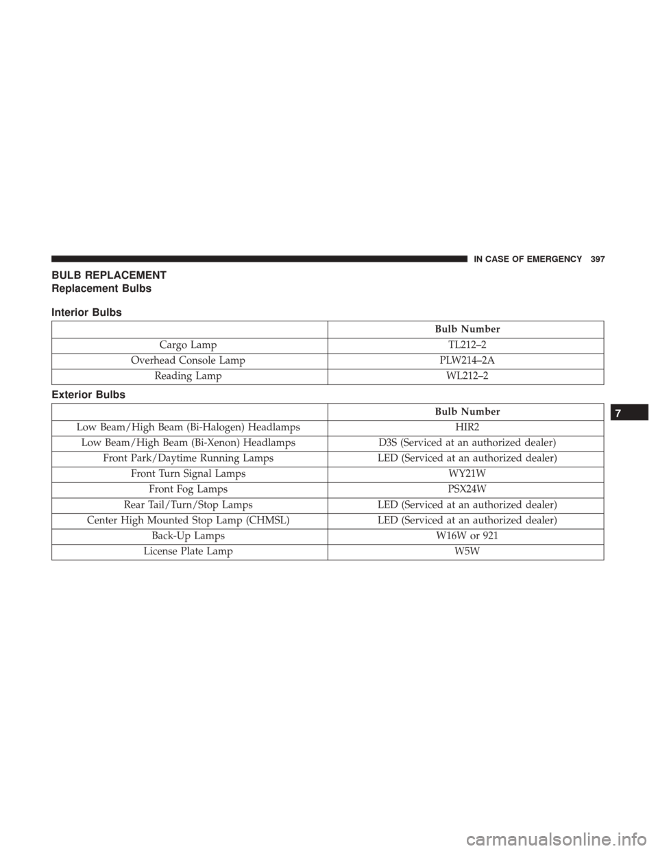
BULB REPLACEMENT
Replacement Bulbs
Interior Bulbs
Bulb Number
Cargo Lamp TL212–2
Overhead Console Lamp PLW214–2A
Reading Lamp WL212–2
Exterior Bulbs
Bulb Number
Low Beam/High Beam (Bi-Halogen) Headlamps HIR2
Low Beam/High Beam (Bi-Xenon) Headlamps D3S (Serviced at an authorized dealer)
Front Park/Daytime Running Lamps LED (Serviced at an authorized dealer)
Front Turn Signal Lamps WY21W
Front Fog Lamps PSX24W
Rear Tail/Turn/Stop Lamps LED (Serviced at an authorized dealer)
Center High Mounted Stop Lamp (CHMSL) LED (Serviced at an authorized dealer)
Back-Up Lamps W16W or 921
License Plate Lamp W5W7
IN CASE OF EMERGENCY 397
Page 400 of 615
Replacing Exterior Bulbs
Bi-Xenon High Intensity Discharge (HID)
Headlamps — If Equipped
The headlamps contain a type of high voltage discharge
light source. High voltage can remain in the circuit even
with the headlamp switch off. Because of this, you should
not attempt to service a HID headlamp light source your-
self. If an HID headlamp light source fails, take your
vehicle to an authorized dealer for service.
NOTE:On vehicles equipped with HID headlamps, when
the headlamps are turned on, there is a blue hue to the
lights. This diminishes and becomes more white after
approximately 10 seconds, as the system charges.
WARNING!
A transient high voltage occurs at the bulb sockets of
HID headlamps when the headlamp switch is turned
ON. It may cause serious electrical shock or electrocu-
tion if not serviced properly. See your authorized
dealer for service.
Bi-Halogen Headlamps
1. Remove the 3 hex head screws from the wheel liner.
2. Pull the exterior edge of the liner towards the tire to gain access to the headlamp bulb cap.
3.
Firmly grasp the cap and rotate it counterclockwise to
unlock it.
4. Firmly grasp the bulb and connector assembly and rotate counterclockwise to remove from the housing.
5. Disconnect the bulb from the electrical connector and then connect the replacement bulb.
CAUTION!
Do not touch the new bulb with your fingers. Oil
contamination will severely shorten bulb life. If the
bulb comes in contact with any oily surface, clean the
bulb with rubbing alcohol.
6. Install the bulb and connector assembly into the head- lamp housing and rotate clockwise to lock it in place.
7. Install the bulb cap in the headlamp housing and rotate clockwise to lock it in place.
8. Install the 3 hex head screws into the wheel liner.
398 IN CASE OF EMERGENCY
Page 402 of 615
6. Pull the bulb to remove it from the socket.
7. Replace the bulb and install the socket.
8. Reconnect the electrical connector.
9. Reinstall the tail lamp housing and screws.
10. Close the liftgate.
Liftgate Mounted Back-up Lamp
1. Open the liftgate.
2. Use a fiber stick or flat blade screw driver to pry thelower trim from the liftgate.
3. Once the trim is loose, pull it back exposing the trim panel.
4. Using a fiber stick or flat blade screw driver, open the trim panel exposing the back of the liftgate lamp.
5. Disconnect the electrical connector.
6.
Twist the socket counterclockwise and remove from lamp.
7. Pull the bulb to remove it from the socket.
8. Replace the bulb, reinstall the socket.
9. Connect the electrical connector. 10. Reinstall the trim panel and the lower trim.
11. Close the liftgate.
License Plate Lamp
1. Using a small screwdriver, press inward the locking tab
on the side of the lamp assembly and pull down on the
lamp assembly for removal.
2. Pull bulb from socket, replace, and reinstall the lamp assembly into place ensuring the locking tab is secure.
FUSES
WARNING!
•When replacing a blown fuse, always use an appropri-
ate replacement fuse with the same amp rating as the
original fuse. Never replace a fuse with another fuse of
higher amp rating. Never replace a blown fuse with
metal wires or any other material. Failure to use proper
fuses may result in serious personal injury, fire and/or
property damage.
•Before replacing a fuse, make sure that the ignition is
off and that all the other services are switched off
and/or disengaged.
(Continued)
400 IN CASE OF EMERGENCY
Page 416 of 615
JACKING AND TIRE CHANGING
WARNING!
•Do not attempt to change a tire on the side of the
vehicle close to moving traffic. Pull far enough off
the road to avoid the danger of being hit when
operating the jack or changing the wheel.
• Being under a jacked-up vehicle is dangerous. The
vehicle could slip off the jack and fall on you. You
could be crushed. Never put any part of your body
under a vehicle that is on a jack. If you need to get
under a raised vehicle, take it to a service center
where it can be raised on a lift.
• Never start or run the engine while the vehicle is on
a jack.
• The jack is designed to be used as a tool for changing
tires only. The jack should not be used to lift the
vehicle for service purposes. The vehicle should be
jacked on a firm level surface only. Avoid ice or
slippery areas.
Jack Location/Spare Tire Stowage
The jack, wheel chocks and spare tire are stowed under the
load floor behind the rear seat.
1. Open the liftgate.
2. Lift the access cover using the load floor handle.
3. Remove the hook from the stowed position on the back side of the load floor and place the hook over the top
body flange and weather seal. This will hold the load
floor up while obtaining the jack and spare tire.
Load Floor Handle
414 IN CASE OF EMERGENCY
Page 419 of 615
Jacking Instructions
WARNING!
Carefully follow these tire changing warnings to help
prevent personal injury or damage to your vehicle:
•
Always park on a firm, level surface as far from the
edge of the roadway as possible before raising the
vehicle.
• Turn on the Hazard Warning flasher.
•
Chock the wheel diagonally opposite the wheel to be
raised.
•Set the parking brake firmly and set the transmission
in PARK.
•Never start or run the engine with the vehicle on a
jack.
•Do not let anyone sit in the vehicle when it is on a jack.
•Do not get under the vehicle when it is on a jack. If you
need to get under a raised vehicle, take it to a service
center where it can be raised on a lift.
•Only use the jack in the positions indicated and for
lifting this vehicle during a tire change.
•If working on or near a roadway, be extremely careful
of motor traffic.
(Continued)
WARNING! (Continued)
•To assure that spare tires, flat or inflated, are securely
stowed, spares must be stowed with the valve stem
facing the ground.
Jack Warning Label
7
IN CASE OF EMERGENCY 417
Page 423 of 615
9. Install the wheel bolts with the threaded end of thewheel bolt toward the wheel. Lightly tighten the wheel
bolts.
WARNING!
To avoid the risk of forcing the vehicle off the jack, do
not tighten the wheel nuts fully until the vehicle has
been lowered. Failure to follow this warning may
result in serious injury.
10. Lower the vehicle to the ground by turning the jack handle counterclockwise.
11. Finish tightening the wheel bolts. Push down on the wrench while at the end of the handle for increased
leverage. Tighten the wheel bolts in a star pattern until
each wheel bolt has been tightened twice. Refer to
“Torque Specifications” in “Technical Specifications”
for the proper lug bolt torque. If in doubt about the
correct tightness, have them checked with a torque
wrench by your authorized dealer or at a service
station. 12. Securely stow the jack, tools, chocks and flat tire.
Assembled Jack
7
IN CASE OF EMERGENCY 421
Page 424 of 615
WARNING!
A loose tire or jack thrown forward in a collision or
hard stop could endanger the occupants of the vehicle.
Always stow the jack parts and the spare tire in the
places provided. Have the deflated (flat) tire repaired
or replaced immediately.
Road Tire Installation
1. Mount the road tire on the axle.
2. Install the remaining wheel bolts with the threaded endof the wheel bolt toward the wheel. Lightly tighten the
wheel bolts.
WARNING!
To avoid the risk of forcing the vehicle off the jack, do
not tighten the wheel nuts fully until the vehicle has
been lowered. Failure to follow this warning may
result in serious injury.
3. Lower the vehicle to the ground by turning the jack handle counterclockwise.
4. Finish tightening the wheel bolts. Push down on the wrench while at the end of the handle for increased
leverage. Tighten the wheel bolts in a star pattern until
each wheel bolt has been tightened twice. Refer to
“Torque Specifications” in “Technical Specifications” for
the proper lug bolt torque. If in doubt about the correct
tightness, have them checked with a torque wrench by
your authorized dealer or service station.
Stowed Tire, Jack And Chock
422 IN CASE OF EMERGENCY
Page 425 of 615
5. Lower the jack until it is free. Remove the wheel chocks.Reassemble the lug wrench to the jack assembly and
stow it in the spare tire area. Secure the assembly using
the means provided. Release the parking brake before
driving the vehicle.
6. After 25 miles (40 km) check the wheel bolt torque with a torque wrench to ensure that all wheel bolts are
properly seated against the wheel.
TIRE SERVICE KIT — IF EQUIPPED
Small punctures up to 1/4 inch (6 mm) in the tire tread can
be sealed with Tire Service Kit. Foreign objects (e.g., screws
or nails) should not be removed from the tire. Tire Service
Kit can be used in outside temperatures down to approxi-
mately -4°F (-20°C).
This kit will provide a temporary tire seal, allowing you to
drive your vehicle up to 100 miles (160 km) with a
maximum speed of 55 mph (90 km/h).
Tire Service Kit Storage
The Tire Service Kit is stowed under the load floor behind
the rear seat.
1. Open the liftgate.
2. Lift the access cover using the load floor handle.
Load Floor Handle
7
IN CASE OF EMERGENCY 423