key JEEP CHEROKEE 2018 Owner handbook (in English)
[x] Cancel search | Manufacturer: JEEP, Model Year: 2018, Model line: CHEROKEE, Model: JEEP CHEROKEE 2018Pages: 312, PDF Size: 4.91 MB
Page 24 of 312
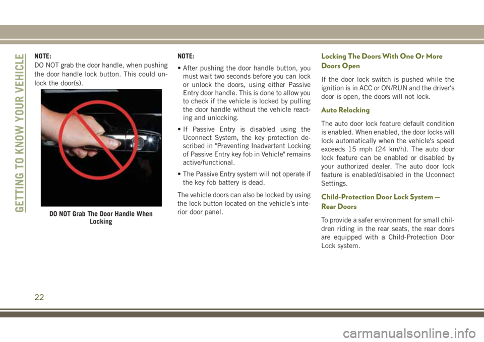
NOTE:
DO NOT grab the door handle, when pushing
the door handle lock button. This could un-
lock the door(s).NOTE:
• After pushing the door handle button, you
must wait two seconds before you can lock
or unlock the doors, using either Passive
Entry door handle. This is done to allow you
to check if the vehicle is locked by pulling
the door handle without the vehicle react-
ing and unlocking.
• If Passive Entry is disabled using the Uconnect System, the key protection de-
scribed in "Preventing Inadvertent Locking
of Passive Entry key fob in Vehicle" remains
active/functional.
• The Passive Entry system will not operate if the key fob battery is dead.
The vehicle doors can also be locked by using
the lock button located on the vehicle’s inte-
rior door panel.Locking The Doors With One Or More
Doors Open
If the door lock switch is pushed while the
ignition is in ACC or ON/RUN and the driver's
door is open, the doors will not lock.
Auto Relocking
The auto door lock feature default condition
is enabled. When enabled, the door locks will
lock automatically when the vehicle's speed
exceeds 15 mph (24 km/h). The auto door
lock feature can be enabled or disabled by
your authorized dealer. The auto door lock
feature is enabled/disabled in the Uconnect
Settings.
Child-Protection Door Lock System —
Rear Doors
To provide a safer environment for small chil-
dren riding in the rear seats, the rear doors
are equipped with a Child-Protection Door
Lock system.DO NOT Grab The Door Handle When LockingGETTING TO KNOW YOUR VEHICLE
22
Page 25 of 312
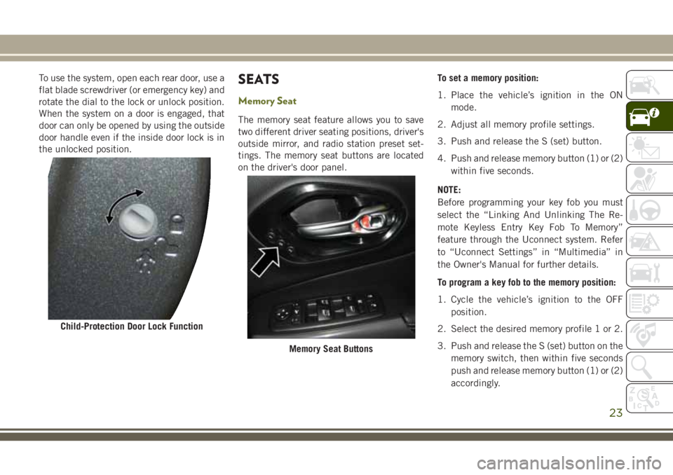
To use the system, open each rear door, use a
flat blade screwdriver (or emergency key) and
rotate the dial to the lock or unlock position.
When the system on a door is engaged, that
door can only be opened by using the outside
door handle even if the inside door lock is in
the unlocked position.SEATS
Memory Seat
The memory seat feature allows you to save
two different driver seating positions, driver's
outside mirror, and radio station preset set-
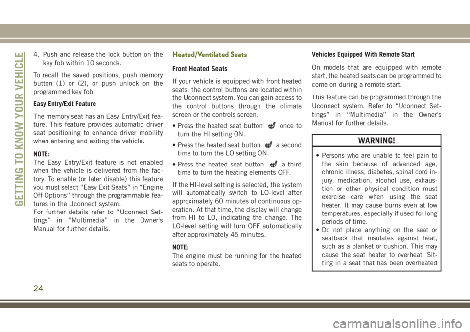
tings. The memory seat buttons are located
on the driver's door panel.To set a memory position:
1. Place the vehicle’s ignition in the ON
mode.
2. Adjust all memory profile settings.
3. Push and release the S (set) button.
4. Push and release memory button (1) or (2) within five seconds.
NOTE:
Before programming your key fob you must
select the “Linking And Unlinking The Re-
mote Keyless Entry Key Fob To Memory”
feature through the Uconnect system. Refer
to “Uconnect Settings” in “Multimedia” in
the Owner's Manual for further details.
To program a key fob to the memory position:
1. Cycle the vehicle’s ignition to the OFF position.
2. Select the desired memory profile 1 or 2.
3. Push and release the S (set) button on the memory switch, then within five seconds
push and release memory button (1) or (2)
accordingly.
Child-Protection Door Lock Function
Memory Seat Buttons
23
Page 26 of 312
4. Push and release the lock button on thekey fob within 10 seconds.
To recall the saved positions, push memory
button (1) or (2), or push unlock on the
programmed key fob.
Easy Entry/Exit Feature
The memory seat has an Easy Entry/Exit fea-
ture. This feature provides automatic driver
seat positioning to enhance driver mobility
when entering and exiting the vehicle.
NOTE:
The Easy Entry/Exit feature is not enabled
when the vehicle is delivered from the fac-
tory. To enable (or later disable) this feature
you must select “Easy Exit Seats” in “Engine
Off Options” through the programmable fea-
tures in the Uconnect system.
For further details refer to “Uconnect Set-
tings” in “Multimedia” in the Owner's
Manual for further details.Heated/Ventilated Seats
Front Heated Seats
If your vehicle is equipped with front heated
seats, the control buttons are located within
the Uconnect system. You can gain access to
the control buttons through the climate
screen or the controls screen.
• Press the heated seat button
once to
turn the HI setting ON.
• Press the heated seat button
a second
time to turn the LO setting ON.
• Press the heated seat button
a third
time to turn the heating elements OFF.
If the HI-level setting is selected, the system
will automatically switch to LO-level after
approximately 60 minutes of continuous op-
eration. At that time, the display will change
from HI to LO, indicating the change. The
LO-level setting will turn OFF automatically
after approximately 45 minutes.
NOTE:
The engine must be running for the heated
seats to operate. Vehicles Equipped With Remote Start
On models that are equipped with remote
start, the heated seats can be programmed to
come on during a remote start.
This feature can be programmed through the
Uconnect system. Refer to “Uconnect Set-
tings” in “Multimedia” in the Owner’s
Manual for further details.
WARNING!
• Persons who are unable to feel pain to
the skin because of advanced age,
chronic illness, diabetes, spinal cord in-
jury, medication, alcohol use, exhaus-
tion or other physical condition must
exercise care when using the seat
heater. It may cause burns even at low
temperatures, especially if used for long
periods of time.
• Do not place anything on the seat or
seatback that insulates against heat,
such as a blanket or cushion. This may
cause the seat heater to overheat. Sit-
ting in a seat that has been overheated
GETTING TO KNOW YOUR VEHICLE
24
Page 46 of 312
Outside Air Intake
Make sure the air intake, located directly in
front of the windshield, is free of obstruc-
tions, such as leaves. Leaves collected in the
air intake may reduce airflow, and if they
enter the plenum, they could plug the water
drains. In Winter months, make sure the air
intake is clear of ice, slush, and snow.
Cabin Air Filter
The climate control system filters out dust
and pollen from the air. Contact an autho-
rized dealer to service your cabin air filter,
and to have it replaced when needed.
WINDOWS
Power Window Controls
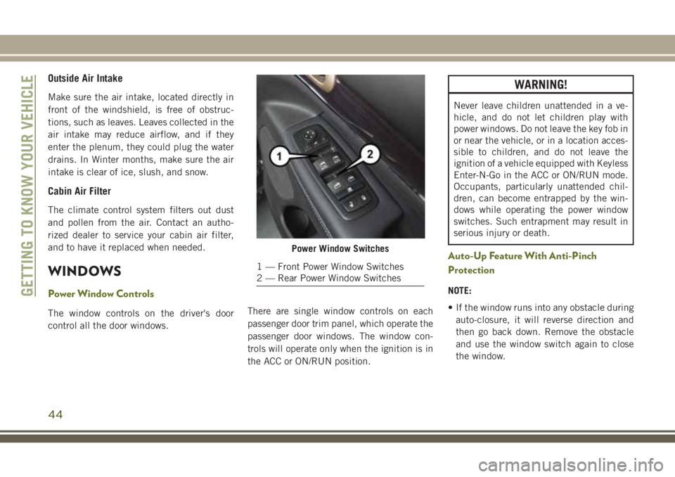
The window controls on the driver's door
control all the door windows.There are single window controls on each
passenger door trim panel, which operate the
passenger door windows. The window con-
trols will operate only when the ignition is in
the ACC or ON/RUN position.
WARNING!
Never leave children unattended in a ve-
hicle, and do not let children play with
power windows. Do not leave the key fob in
or near the vehicle, or in a location acces-
sible to children, and do not leave the
ignition of a vehicle equipped with Keyless
Enter-N-Go in the ACC or ON/RUN mode.
Occupants, particularly unattended chil-
dren, can become entrapped by the win-
dows while operating the power window
switches. Such entrapment may result in
serious injury or death.
Auto-Up Feature With Anti-Pinch
Protection
NOTE:
• If the window runs into any obstacle during
auto-closure, it will reverse direction and
then go back down. Remove the obstacle
and use the window switch again to close
the window.
Power Window Switches
1 — Front Power Window Switches
2 — Rear Power Window Switches
GETTING TO KNOW YOUR VEHICLE
44
Page 49 of 312
Manual Open
To open the shade, push and hold the switch
rearward. The shade will open and stop auto-
matically at the half-open position.
Push and hold the shade switch rearward
again and the shade will open automatically
to the full-open position.
Express Close
Push the switch forward and release it within
one-half second and the shade will close
automatically from any position.
Manual Close
To close the shade, push and hold the switch
in the forward position.
Pinch Protection Feature
This feature will detect an obstruction in the
opening of the sunroof during Express Close
operation. If an obstruction in the path of the
sunroof is detected, the sunroof will auto-
matically retract. Remove the obstruction if
this occurs. Next, push the switch forward
and release to Express Close.NOTE:
If three consecutive sunroof close attempts
result in Pinch Protect reversals, the fourth
close attempt will be a Manual Close move-
ment with Pinch Protect disabled.
WARNING!
• Do not let children play with the sunroof.
Never leave children unattended in a
vehicle, or with access to an unlocked
vehicle. Do not leave the key fob in or
near the vehicle, and do not leave the
ignition of a vehicle equipped with Key-
less Enter-N-Go in the ACC or ON/RUN
mode. Occupants, particularly unat-
tended children, can become entrapped
by the power sunroof while operating the
power sunroof switch. Such entrapment
may result in serious injury or death.
• In a collision, there is a greater risk of
being thrown from a vehicle with an
open sunroof. You could also be severely
injured or killed. Always fasten your seat
belt properly and make sure all passen-
gers are properly secured.
WARNING!
• Do not allow small children to operatethe sunroof. Never allow your fingers,
other body parts, or any object to project
through the sunroof opening. Injury may
result.
Sunroof Maintenance
Use only a non-abrasive cleaner and a soft
cloth to clean the glass panel.
HOOD
Opening The Hood
Two latches must be released to open the
hood.
1. Pull the hood release lever located under the driver’s side of the instrument panel.
47
Page 50 of 312
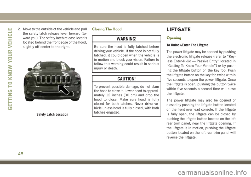
2. Move to the outside of the vehicle and pullthe safety latch release lever forward (to-
ward you). The safety latch release lever is
located behind the front edge of the hood,
slightly off-center to the right.Closing The Hood
WARNING!
Be sure the hood is fully latched before
driving your vehicle. If the hood is not fully
latched, it could open when the vehicle is
in motion and block your vision. Failure to
follow this warning could result in serious
injury or death.
CAUTION!
To prevent possible damage, do not slam
the hood to close it. Lower hood to approxi-
mately 12 inches (30 cm) and drop the
hood to close. Make sure hood is fully
closed for both latches. Never drive ve-
hicle unless hood is fully closed, with both
latches engaged.
LIFTGATE
Opening
To Unlock/Enter The Liftgate
The power liftgate may be opened by pushing
the electronic liftgate release (refer to “Key-
less Enter-N-Go — Passive Entry” located in
“Getting To Know Your Vehicle”) or by push-
ing the liftgate button on the key fob. Push
the liftgate button on the key fob twice within
five seconds to open the power liftgate. Once
the liftgate is open, pushing the button twice
within five seconds a second time will close
the liftgate.
The power liftgate may also be opened or
closed by pushing the liftgate button located
on the front overhead console. If the liftgate
is fully open, the liftgate can be closed by
pushing the liftgate button located on the left
rear trim panel, near the liftgate opening. If
the liftgate is in motion, pushing the liftgate
button located on the left rear trim panel will
reverse the liftgate.
Safety Latch Location
GETTING TO KNOW YOUR VEHICLE
48
Page 51 of 312
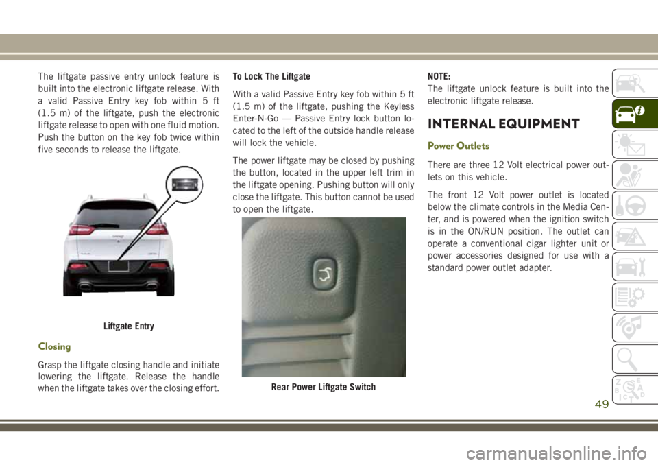
The liftgate passive entry unlock feature is
built into the electronic liftgate release. With
a valid Passive Entry key fob within 5 ft
(1.5 m) of the liftgate, push the electronic
liftgate release to open with one fluid motion.
Push the button on the key fob twice within
five seconds to release the liftgate.
Closing
Grasp the liftgate closing handle and initiate
lowering the liftgate. Release the handle
when the liftgate takes over the closing effort.To Lock The Liftgate
With a valid Passive Entry key fob within 5 ft
(1.5 m) of the liftgate, pushing the Keyless
Enter-N-Go — Passive Entry lock button lo-
cated to the left of the outside handle release
will lock the vehicle.
The power liftgate may be closed by pushing
the button, located in the upper left trim in
the liftgate opening. Pushing button will only
close the liftgate. This button cannot be used
to open the liftgate.
NOTE:
The liftgate unlock feature is built into the
electronic liftgate release.
INTERNAL EQUIPMENT
Power Outlets
There are three 12 Volt electrical power out-
lets on this vehicle.
The front 12 Volt power outlet is located
below the climate controls in the Media Cen-
ter, and is powered when the ignition switch
is in the ON/RUN position. The outlet can
operate a conventional cigar lighter unit or
power accessories designed for use with a
standard power outlet adapter.
Liftgate Entry
Rear Power Liftgate Switch
49
Page 87 of 312
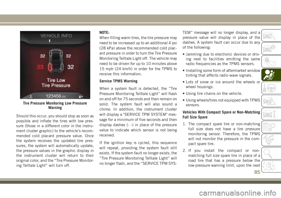
Should this occur, you should stop as soon as
possible and inflate the tires with low pres-
sure (those in a different color in the instru-
ment cluster graphic) to the vehicle’s recom-
mended cold placard pressure value. Once
the system receives the updated tire pres-
sures, the system will automatically update,
the pressure values in the graphic display in
the instrument cluster will return to their
original color, and the “Tire Pressure Monitor-
ing Telltale Light” will turn off.NOTE:
When filling warm tires, the tire pressure may
need to be increased up to an additional 4 psi
(28 kPa) above the recommended cold plac-
ard pressure in order to turn the Tire Pressure
Monitoring Telltale Light off. The vehicle may
need to be driven for up to 10 minutes above
15 mph (24 km/h) in order for the TPMS to
receive this information.
Service TPMS Warning
When a system fault is detected, the “Tire
Pressure Monitoring Telltale Light” will flash
on and off for 75 seconds and then remain on
solid. The system fault will also sound a
chime. In addition, the instrument cluster
will display a "SERVICE TPM SYSTEM" mes-
sage for a minimum of five seconds and then
display dashes (- -) in place of the pressure
value to indicate which sensor is not being
received.
If the ignition key is cycled, this sequence
will repeat, providing the system fault still
exists. If the system fault no longer exists, the
“Tire Pressure Monitoring Telltale Light” will
no longer flash, and the “SERVICE TPM SYS-
TEM” message will no longer display, and a
pressure value will display in place of the
dashes. A system fault can occur due to any
of the following:
• Jamming due to electronic devices or driv-
ing next to facilities emitting the same
radio frequencies as the TPMS sensors.
• Installing some form of aftermarket window tinting that affects radio wave signals.
• Lots of snow or ice around the wheels or wheel housings.
• Using tire chains on the vehicle.
• Using wheels/tires not equipped with TPMS sensors.
Vehicles With Compact Spare or Non-Matching
Full Size Spare
1. The compact spare tire or non-matching full size does not have a tire pressure
monitoring sensor. Therefore, the TPMS
will not monitor the pressure in the com-
pact spare tire.
2. If you install the compact or non- matching full size spare tire in place of a
road tire that has a pressure below the
low-pressure warning limit, upon the next
Tire Pressure Monitoring Low Pressure Warning
85
Page 88 of 312
ignition key cycle, the “TPMS Telltale
Light” will remain on and a chime will
sound. In addition, the graphic in the
instrument cluster will still display a dif-
ferent color pressure value.
3. After driving the vehicle for up to 10 min- utes above 15 mph (24 km/h), the “TPMS
Telltale Light” will flash on and off for
75 seconds and then remain on solid. In
addition, the instrument cluster will dis-
play a “Service Tire Pressure System”
message for five seconds and then display
dashes (- -) in place of the pressure value.
4. For each subsequent ignition key cycle, a chime will sound, the “TPMS Telltale
Light” will flash on and off for 75 seconds
and then remain on solid, and the instru-
ment cluster will display a “SERVICE
TPM SYSTEM” message for five seconds
and then display dashes (- -) in place of
the pressure value.
5. Once you repair or replace the original road tire and reinstall it on the vehicle in
place of the compact spare or non-
matching full size, the TPMS will update
automatically. In addition, the “TPMS Telltale Light” will turn off and the
graphic in the instrument cluster will dis-
play a new pressure value instead of
dashes (- -), as long as no tire pressure is
below the low-pressure warning limit in
any of the four active road tires. The
vehicle may need to be driven for up to
10 minutes above 15 mph (24 km/h) in
order for the TPMS to receive this
information.
TPMS Deactivation — If Equipped
The TPMS can be deactivated if replacing all
four wheel and tire assemblies (road tires)
with wheel and tire assemblies that do not
have TPMS Sensors, such as when installing
winter wheel and tire assemblies on your
vehicle.
To deactivate the TPMS, first replace all four
wheel and tire assemblies (road tires) with
tires not equipped with Tire Pressure Moni-
toring (TPM) Sensors. Then, drive the vehicle
for 10 minutes above 15 mph (24 km/h). The
TPMS will chime, the "TPM Telltale Light"
will flash on and off for 75 seconds and then remain on. The instrument cluster will dis-
play the “SERVICE TPM SYSTEM” message
and then display dashes (--) in place of the
pressure values.
Beginning with the next ignition cycle, the
TPMS will no longer chime or display the
“SERVICE TPM SYSTEM” message in the
instrument cluster but dashes (--) will remain
in place of the pressure values.
To reactivate the TPMS, replace all four
wheel and tire assemblies (road tires) with
tires equipped with TPM sensors. Then, drive
the vehicle for up to 10 minutes above
15 mph (24 km/h). The TPMS will chime, the
"TPM Telltale Light" will flash on and off for
75 seconds and then turn off. The instrument
cluster will display the “SERVICE TPM SYS-
TEM” message and then display pressure
values in place of the dashes. On the next
ignition cycle the "SERVICE TPM SYSTEM"
message will no longer be displayed as long
as no system fault exists.
SAFETY
86
Page 105 of 312
Your vehicle may also be designed to perform
any of these other functions in response to
the Enhanced Accident Response System:
• Turn off the Fuel Filter Heater, Turn off theHVAC Blower Motor, Close the HVAC Circu-
lation Door
• Cut off battery power to the: – Engine
– Electric Motor (if equipped)
– Electric power steering
– Brake booster
– Electric park brake
– Automatic transmission gear selector
– Horn
– Front wiper
– Headlamp washer pump NOTE:
After an accident, remember to cycle the
ignition to the STOP (OFF/LOCK) position
and remove the key from the ignition switch
to avoid draining the battery. Carefully check
the vehicle for fuel leaks in the engine com-
partment and on the ground near the engine
compartment and fuel tank before resetting
the system and starting the engine. If there
are no fuel leaks or damage to the vehicle
electrical devices (e.g. headlights) after an
accident, reset the system by following the
procedure described below.
Enhanced Accident Response System Reset
Procedure
In order to reset the Enhanced Accident Re-
sponse System functions after an event, the
ignition switch must be changed from igni-
tion START or ON/RUN to ignition OFF. Care-
fully check the vehicle for fuel leaks in the
engine compartment and on the ground near
the engine compartment and fuel tank before
resetting the system and starting the engine.
Maintaining Your Air Bag System
WARNING!
•Modifications to any part of the air bag
system could cause it to fail when you
need it. You could be injured if the air bag
system is not there to protect you. Do not
modify the components or wiring, includ-
ing adding any kind of badges or stickers
to the steering wheel hub trim cover or the
upper right side of the instrument panel.
Do not modify the front bumper, vehicle
body structure, or add aftermarket side
steps or running boards.
• It is dangerous to try to repair any part of
the air bag system yourself. Be sure to
tell anyone who works on your vehicle
that it has an air bag system.
• Do not attempt to modify any part of your
air bag system. The air bag may inflate
accidentally or may not function prop-
erly if modifications are made. Take your
vehicle to an authorized dealer for any
air bag system service. If your seat, in-
cluding your trim cover and cushion,
needs to be serviced in any way (includ-
103