sensor JEEP CHEROKEE 2018 Owner handbook (in English)
[x] Cancel search | Manufacturer: JEEP, Model Year: 2018, Model line: CHEROKEE, Model: JEEP CHEROKEE 2018Pages: 312, PDF Size: 4.91 MB
Page 88 of 312
ignition key cycle, the “TPMS Telltale
Light” will remain on and a chime will
sound. In addition, the graphic in the
instrument cluster will still display a dif-
ferent color pressure value.
3. After driving the vehicle for up to 10 min- utes above 15 mph (24 km/h), the “TPMS
Telltale Light” will flash on and off for
75 seconds and then remain on solid. In
addition, the instrument cluster will dis-
play a “Service Tire Pressure System”
message for five seconds and then display
dashes (- -) in place of the pressure value.
4. For each subsequent ignition key cycle, a chime will sound, the “TPMS Telltale
Light” will flash on and off for 75 seconds
and then remain on solid, and the instru-
ment cluster will display a “SERVICE
TPM SYSTEM” message for five seconds
and then display dashes (- -) in place of
the pressure value.
5. Once you repair or replace the original road tire and reinstall it on the vehicle in
place of the compact spare or non-
matching full size, the TPMS will update
automatically. In addition, the “TPMS Telltale Light” will turn off and the
graphic in the instrument cluster will dis-
play a new pressure value instead of
dashes (- -), as long as no tire pressure is
below the low-pressure warning limit in
any of the four active road tires. The
vehicle may need to be driven for up to
10 minutes above 15 mph (24 km/h) in
order for the TPMS to receive this
information.
TPMS Deactivation — If Equipped
The TPMS can be deactivated if replacing all
four wheel and tire assemblies (road tires)
with wheel and tire assemblies that do not
have TPMS Sensors, such as when installing
winter wheel and tire assemblies on your
vehicle.
To deactivate the TPMS, first replace all four
wheel and tire assemblies (road tires) with
tires not equipped with Tire Pressure Moni-
toring (TPM) Sensors. Then, drive the vehicle
for 10 minutes above 15 mph (24 km/h). The
TPMS will chime, the "TPM Telltale Light"
will flash on and off for 75 seconds and then remain on. The instrument cluster will dis-
play the “SERVICE TPM SYSTEM” message
and then display dashes (--) in place of the
pressure values.
Beginning with the next ignition cycle, the
TPMS will no longer chime or display the
“SERVICE TPM SYSTEM” message in the
instrument cluster but dashes (--) will remain
in place of the pressure values.
To reactivate the TPMS, replace all four
wheel and tire assemblies (road tires) with
tires equipped with TPM sensors. Then, drive
the vehicle for up to 10 minutes above
15 mph (24 km/h). The TPMS will chime, the
"TPM Telltale Light" will flash on and off for
75 seconds and then turn off. The instrument
cluster will display the “SERVICE TPM SYS-
TEM” message and then display pressure
values in place of the dashes. On the next
ignition cycle the "SERVICE TPM SYSTEM"
message will no longer be displayed as long
as no system fault exists.
SAFETY
86
Page 97 of 312
WARNING!
the seat belt or children who are using
booster seats. The locked mode is only
used to install rear-facing or forward-
facing child restraints that have a har-
ness for restraining the child.
Supplemental Restraint Systems (SRS)
Some of the safety features described in this
section may be standard equipment on some
models, or may be optional equipment on
others. If you are not sure, ask your autho-
rized dealer.
The air bag system must be ready to protect
you in a collision. The Occupant Restraint
Controller (ORC) monitors the internal cir-
cuits and interconnecting wiring associated
with the electrical Air Bag System Compo-
nents. Your vehicle may be equipped with the
following Air Bag System Components:
Air Bag System Components
• Occupant Restraint Controller (ORC)
• Air Bag Warning Light
• Steering Wheel and Column• Instrument Panel
• Knee Impact Bolsters
• Driver and Front Passenger Air Bags
• Seat Belt Buckle Switch
• Supplemental Side Air Bags
• Supplemental Knee Air Bags
• Front and Side Impact Sensors
• Seat Belt Pretensioners
Air Bag Warning Light
The ORC monitors the readiness of the
electronic parts of the air bag system when-
ever the ignition switch is in the START or
ON/RUN position. If the ignition switch is in
the OFF position or in the ACC position, the
air bag system is not on and the air bags will
not inflate.
The ORC contains a backup power supply
system that may deploy the air bag system
even if the battery loses power or it becomes
disconnected prior to deployment.
The ORC turns on the Air Bag Warning Light
in the instrument panel for approximately
four to eight seconds for a self-check when the ignition switch is first in the ON/RUN
position. After the self-check, the Air Bag
Warning Light will turn off. If the ORC detects
a malfunction in any part of the system, it
turns on the Air Bag Warning Light, either
momentarily or continuously. A single chime
will sound to alert you if the light comes on
again after initial startup.
The ORC also includes diagnostics that will
illuminate the instrument panel Air Bag
Warning Light if a malfunction is detected
that could affect the air bag system. The
diagnostics also record the nature of the
malfunction. While the air bag system is
designed to be maintenance free, if any of the
following occurs, have an authorized dealer
service the air bag system immediately.
• The Air Bag Warning Light does not come
on during the four to eight seconds when
the ignition switch is first in the ON/RUN
position.
• The Air Bag Warning Light remains on after the four to eight-second interval.
• The Air Bag Warning Light comes on inter- mittently or remains on while driving.
95
Page 99 of 312
WARNING!
• Being too close to the steering wheel orinstrument panel during front air bag
deployment could cause serious injury,
including death. Air bags need room to
inflate. Sit back, comfortably extending
your arms to reach the steering wheel or
instrument panel.
• Never place a rear-facing child restraint
in front of an air bag. A deploying pas-
senger front air bag can cause death or
serious injury to a child 12 years or
younger, including a child in a rear-
facing child restraint.
• Only use a rear-facing child restraint in
the rear seat of a vehicle with a rear seat.
Driver And Passenger Front Air Bag Features
The front air bag system is designed to inflate
based on the severity and type of collision as
determined by the Occupant Restraint Con-
troller (ORC), which may receive information
from the front impact sensors (if equipped) or
other system components. The driver front air
bag system has a single stage air bag. The
passenger front air bag system has a multi- stage front air bag. The first stage inflator is
triggered immediately during an impact that
requires air bag deployment. For the multi-
stage air bag, a low energy output is used in
less severe collisions. A higher energy output
is used for more severe collisions.
This vehicle may be equipped with a driver
and/or front passenger seat belt buckle
switch that detects whether the driver or front
passenger seat belt is buckled. The seat belt
buckle switch may adjust the inflation rate of
the passenger multistage Front Air Bag.
WARNING!
• No objects should be placed over or near
the air bag on the instrument panel or
steering wheel because any such objects
could cause harm if the vehicle is in a
collision severe enough to cause the air
bag to inflate.
• Do not put anything on or around the air
bag covers or attempt to open them
manually. You may damage the air bags
and you could be injured because the air
bags may no longer be functional. The
WARNING!
protective covers for the air bag cushions
are designed to open only when the air
bags are inflating.
• Relying on the air bags alone could lead
to more severe injuries in a collision. The
air bags work with your seat belt to
restrain you properly. In some collisions,
air bags won’t deploy at all. Always wear
your seat belts even though you have air
bags.
Front Air Bag Operation
Front Air Bags are designed to provide addi-
tional protection by supplementing the seat
belts. Front air bags are not expected to
reduce the risk of injury in rear, side, or
rollover collisions. The front air bags will not
deploy in all frontal collisions, including
some that may produce substantial vehicle
damage — for example, some pole collisions,
truck underrides, and angle offset collisions.
97
Page 100 of 312
On the other hand, depending on the type
and location of impact, front air bags may
deploy in crashes with little vehicle front-end
damage but that produce a severe initial
deceleration.
Because air bag sensors measure vehicle
deceleration over time, vehicle speed and
damage by themselves are not good indica-
tors of whether or not an air bag should have
deployed.
Seat belts are necessary for your protection in
all collisions, and also are needed to help
keep you in position, away from an inflating
air bag.
When the ORC detects a collision requiring
the front air bags, it signals the inflator units.
A large quantity of non-toxic gas is generated
to inflate the front air bags.
The steering wheel hub trim cover and the
upper passenger side of the instrument panel
separate and fold out of the way as the air
bags inflate to their full size. The front air
bags fully inflate in less time than it takes to
blink your eyes. The front air bags then
quickly deflate while helping to restrain the
driver and front passenger.Knee Impact Bolsters
The Knee Impact Bolsters help protect the
knees of the driver and front passenger, and
position the front occupants for improved
interaction with the front air bags.
WARNING!
• Do not drill, cut, or tamper with the kneeimpact bolsters in any way.
• Do not mount any accessories to the
knee impact bolsters such as alarm
lights, stereos, citizen band radios, etc.
Supplemental Driver Knee Air Bag
This vehicle is equipped with a Supplemental
Driver Knee Air Bag mounted in the instru-
ment panel below the steering column. The
Supplemental Driver Knee Air Bag provides
enhanced protection during a frontal impact
by working together with the seat belts, pre-
tensioners, and front air bags.
Supplemental Side Air Bags
Supplemental Seat-Mounted Side Air Bags
(SABs) (if equipped)
Your vehicle may be equipped with Supple-
mental Seat-Mounted Side Air Bags (SABs).
If your vehicle is equipped with Supplemen-
tal Seat-Mounted Side Air Bags (SABs),
please refer to the information below.
Supplemental Seat-Mounted Side Air Bags
(SABs) are located in the outboard side of the
front seats. The SABs are marked with “SRS
AIRBAG” or “AIRBAG” on a label or on the
seat trim on the outboard side of the seats.
SAFETY
98
Page 102 of 312
with enough force to injure occupants if they
are not belted and seated properly, or if items
are positioned in the area where the SABICs
inflate. Children are at an even greater risk of
injury from a deploying air bag.
The SABICs (if equipped with SABICs) may
help reduce the risk of partial or complete
ejection of vehicle occupants through side
windows in certain side impact events.
WARNING!
• Do not mount equipment, or stack lug-gage or other cargo up high enough to
block the deployment of the SABICs.
The trim covering above the side win-
dows where the SABIC and its deploy-
ment path are located should remain
free from any obstructions.
• In order for the SABICs to work as in-
tended, do not install any accessory
items in your vehicle which could alter
the roof. Do not add an aftermarket
sunroof to your vehicle. Do not add roof
racks that require permanent attach-
ments (bolts or screws) for installation
WARNING!
on the vehicle roof. Do not drill into the
roof of the vehicle for any reason.
Side Impacts
The Side Air Bags are designed to activate in
certain side impacts. The Occupant Restraint
Controller (ORC) determines whether the de-
ployment of the Side Air Bags in a particular
impact event is appropriate, based on the
severity and type of collision. The side impact
sensors aid the ORC in determining the ap-
propriate response to impact events. The
system is calibrated to deploy the Side Air
Bags on the impact side of the vehicle during
impacts that require Side Air Bag occupant
protection. In side impacts, the Side Air Bags
deploy independently; a left side impact de-
ploys the left Side Air Bags only and a right-
side impact deploys the right Side Air Bags
only. Vehicle damage by itself is not a good
indicator of whether or not Side Air Bags
should have deployed
The Side Air Bags will not deploy in all side
collisions, including some collisions at cer-
tain angles, or some side collisions that do not impact the area of the passenger com-
partment. The Side Air Bags may deploy
during angled or offset frontal collisions
where the front air bags deploy.
Side Air Bags are a supplement to the seat
belt restraint system. Side Air Bags deploy in
less time than it takes to blink your eyes.
WARNING!
• Occupants, including children, who are
up against or very close to Side Air Bags
can be seriously injured or killed. Occu-
pants, including children, should never
lean on or sleep against the door, side
windows, or area where the side air bags
inflate, even if they are in an infant or
child restraint.
• Seat belts (and child restraints where
appropriate) are necessary for your pro-
tection in all collisions. They also help
keep you in position, away from an in-
flating Side Air Bag. To get the best
protection from the Side Air Bags, occu-
pants must wear their seat belts properly
and sit upright with their backs against
SAFETY
100
Page 103 of 312
WARNING!
the seats. Children must be properly
restrained in a child restraint or booster
seat that is appropriate for the size of the
child.
WARNING!
• Side Air Bags need room to inflate. Donot lean against the door or window. Sit
upright in the center of the seat.
• Being too close to the Side Air Bags
during deployment could cause you to
be severely injured or killed.
• Relying on the Side Air Bags alone could
lead to more severe injuries in a colli-
sion. The Side Air Bags work with your
seat belt to restrain you properly. In
some collisions, Side Air Bags won’t
deploy at all. Always wear your seat belt
even though you have Side Air Bags.
NOTE:
Air bag covers may not be obvious in the
interior trim, but they will open during air bag
deployment. Rollover Events — If Equipped With Rollover
Sensing
Side Air Bags are designed to activate in
certain rollover events. The Occupant Re-
straint Controller (ORC) determines whether
the deployment of the Side Air Bags in a
particular rollover event is appropriate, based
on the severity and type of collision. Vehicle
damage by itself is not a good indicator of
whether or not Side Air Bags should have
deployed.
The Side Air Bags will not deploy in all
rollover events. The rollover sensing-system
determines if a rollover event may be in
progress and whether deployment is appro-
priate. A slower-developing event may deploy
the seat belt pretensioners on both sides of
the vehicle. A faster-developing event may
deploy the seat belt pretensioners as well as
the Side Air Bags on both sides of the vehicle.
The rollover sensing-system may also deploy
the seat belt pretensioners, with or without
the Side Air Bags, on both sides of the vehicle
if the vehicle experiences a near rollover
event.
The SABICs may help reduce the risk of
partial or complete ejection of vehicle occu-
pants through side windows in certain roll-
over or side impact events.
Air Bag System Components
NOTE:
The Occupant Restraint Controller (ORC)
monitors the internal circuits and intercon-
necting wiring associated with electrical Air
Bag System Components listed below:
• Occupant Restraint Controller (ORC)
• Air Bag Warning Light
• Steering Wheel and Column
• Instrument Panel
• Knee Impact Bolsters
• Driver and Front Passenger Air Bags
• Seat Belt Buckle Switch
• Supplemental Side Air Bags
• Supplemental Knee Air Bags
• Front and Side Impact Sensors
• Seat Belt Pretensioners
101
Page 122 of 312
Deactivation.................145
Setting The Following Distance ......145
Changing Modes ..............146
PARKSENSE REAR PARK
ASSIST ...................147
ParkSense Sensors .............147
Enabling And Disabling ParkSense . . .147
Instrument Cluster Display —
Warning ....................147
ParkSense System Usage Precautions . .148
PARKSENSE FRONT AND REAR
PARKASSIST...............149
ParkSense Sensors .............149
Enabling And Disabling ParkSense . . .149
Engagement/Disengagement .......150
Operation With A Trailer ..........150
General Warnings ..............150
PARKSENSE ACTIVE
PARKASSIST ..............150
Enabling And Disabling ParkSense
Active Park Assist .............150
LANESENSE................151
LaneSense Operation ............151
Turning LaneSense On Or Off .......152
LaneSense Warning Message .......152
Changing LaneSense Status ........154
PARKVIEW REAR BACK-UP
CAMERA..................154
Symbols And Messages On
The Display ..................154
REFUELING THE VEHICLE .....155
TRAILER TOWING ...........156
Trailer Towing Weights (Maximum Trailer
Weight Ratings)...............156
RECREATIONAL TOWING (BEHIND
MOTORHOME, ETC.) ..........157
Towing This Vehicle Behind Another
Vehicle................... .157
Recreational Towing — Front-Wheel
Drive (FWD) Models ............158
Recreational Towing — 4x4 Models . . .158
STARTING AND OPERATING
120
Page 145 of 312
Accelerating For Passing
Press the accelerator as you would normally.
When the pedal is released, the vehicle will
return to the set speed.
Deactivation
A soft tap on the brake pedal, pushing the
CANC button, or normal brake pressure while
slowing the vehicle will deactivate the Speed
Control without erasing the set speed from
memory.
Pushing the on/off button or turning the igni-
tion switch OFF erases the set speed from
memory.
ADAPTIVE CRUISE
CONTROL (ACC)
If your vehicle is equipped with Adaptive
Cruise Control, the controls operate exactly
the same as the Speed Control with only a
couple of differences. With this option, you
can set a specified distance you would like to
maintain between you and the vehicle in front
of you.If the ACC sensor detects a vehicle ahead,
ACC will apply limited braking or acceleration
automatically to maintain a preset following
distance, while matching the speed of the
vehicle ahead.If the sensor does not detect a vehicle ahead
of you, ACC will maintain a fixed set speed.
Activation
Push and release the Adaptive Cruise Control
(ACC) on/off button.
“ACC READY” will appear in the instrument
cluster display to indicate the ACC is on.
Setting A Desired ACC Speed
When the vehicle reaches the speed desired,
push the SET
(+)button or the SET (-)button
and release. The instrument cluster display
will show the set speed.
If the system is set when the vehicle speed is
below 19 mph (30 km/h), the set speed shall
be defaulted to 19 mph (30 km/h). If the
system is set when the vehicle speed is above
19 mph (30 km/h), the set speed shall be the
current speed of the vehicle.
NOTE:
ACC cannot be set if there is a stationary
vehicle in front of your vehicle in close prox-
imity.
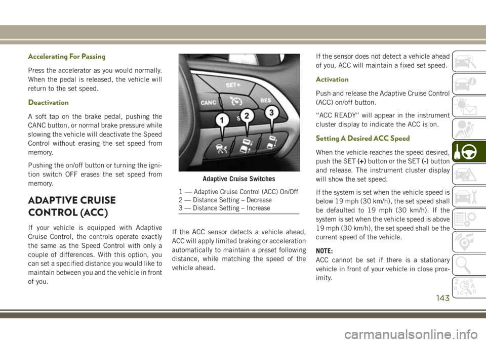
Adaptive Cruise Switches
1—Adaptive Cruise Control (ACC) On/Off
2 — Distance Setting – Decrease
3 — Distance Setting – Increase
143
Page 149 of 312
WARNING!
• When entering a turn lane or highway offramp; when driving on roads that are
winding, icy, snow-covered, slippery, or
have steep uphill or downhill slopes.
• When towing a trailer up or down steep
slopes.
• When circumstances do not allow safe
driving at a constant speed.
The Cruise Control system has two control
modes:
•
Adaptive Cruise Control mode for main-
taining an appropriate distance between
vehicles.
• Normal (Fixed Speed) Cruise Control
mode for cruising at a constant preset
speed. For additional information, refer
to “Normal (Fixed Speed) Cruise Control
Mode” in your Owner’s Manual for fur-
ther information.
Normal (Fixed Speed) Cruise Control will not
react to preceding vehicles. Always be aware
of the mode selected. You can change the
mode by using the Cruise Control buttons.
The two control modes function differently.
Always confirm which mode is selected.
PARKSENSE REAR PARK
ASSIST
ParkSense Sensors
The four ParkSense sensors, located in the
rear fascia/bumper, monitor the area behind
the vehicle that is within the sensors’ field of
view. The sensors can detect obstacles from
approximately 12 inches (30 cm) up to
79 inches (200 cm) from the rear fascia/
bumper in the horizontal direction, depend-
ing on the location, type and orientation of
the obstacle.
Enabling And Disabling ParkSense
ParkSense can be enabled and disabled with
the ParkSense switch, located on the switch
panel below the Uconnect display.
When the ParkSense switch is pushed to
disable the system, the instrument cluster
display will show the “PARKSENSE OFF”
message for approximately five seconds. Re-
fer to “Instrument Cluster Display” in “Get-
ting To Know Your Instrument Panel” in your Owner’s Manual for further information.
When the gear selector is moved to REVERSE
and the system is disabled, the instrument
cluster display will show the “PARKSENSE
OFF” message for as long as the vehicle is in
REVERSE.
The ParkSense switch LED will be on when
ParkSense is disabled or requires service.
The ParkSense switch LED will be off when
the system is enabled. If the ParkSense
switch is pushed, and requires service, the
ParkSense switch LED will blink momen-
tarily, and then the LED will be on.
Instrument Cluster Display — Warning
The ParkSense Warning screen will only be
displayed if Sound and Display is selected
from the Customer - Programmable Features
section of the Uconnect System. Refer to
"Uconnect Settings” in “Multimedia” in your
Owner's Manual for further information.
147
Page 150 of 312
The ParkSense Warning screen is located
within the instrument cluster display. It pro-
vides visual warnings to indicate the distance
between the rear fascia/bumper and the de-
tected obstacle. Refer to “Instrument Cluster
Display” in your Owner's Manual for further
information.
ParkSense System Usage Precautions
• Ensure that the rear bumper is free of snow,ice, mud, dirt and debris to keep the
ParkSense system operating properly.
• Jackhammers, large trucks, and other vi- brations could affect the performance of
ParkSense.
• When you turn ParkSense off, the instru- ment cluster display will read
“PARKSENSE OFF”. Furthermore, once
you turn ParkSense off, it remains off until
you turn it on again, even if you cycle the
ignition.
• When you move the gear selector to the REVERSE position and ParkSense is
turned off, the instrument cluster display
will show a “PARKSENSE OFF” message
for as long as the vehicle is in REVERSE. • ParkSense, when on, will reduce the vol-
ume of the radio when it is sounding a tone.
• Clean the ParkSense sensors regularly, tak- ing care not to scratch or damage them.
The sensors must not be covered with ice,
snow, slush, mud, dirt or debris. Failure to
do so can result in the system not working
properly. The ParkSense system might not
detect an obstacle behind the fascia/
bumper, or it could provide a false indica-
tion that an obstacle is behind the fascia/
bumper.
• Use the ParkSense switch to turn the ParkSense system OFF if objects such as
bicycle carriers, etc. are placed within
12 inches (30 cm) from the rear fascia/
bumper. Failure to do so can result in the
system misinterpreting a close object as a
sensor problem, causing the “PARKSENSE
UNAVAILABLE SERVICE REQUIRED”
message to be displayed in the instrument
cluster display.
• ParkSense should be disabled when the liftgate is in the open position and the
vehicle is in REVERSE. An open liftgate
could provide a false indication that an
obstacle is behind the vehicle.
WARNING!
• Drivers must be careful when backing up
even when using ParkSense. Always
check carefully behind your vehicle,
look behind you, and be sure to check
for pedestrians, animals, other vehicles,
obstructions, and blind spots before
backing up. You are responsible for
safety and must continue to pay atten-
tion to your surroundings. Failure to do
so can result in serious injury or death.
• Before using ParkSense, it is strongly
recommended that the ball mount and
hitch ball assembly is disconnected
from the vehicle when the vehicle is not
used for towing. Failure to do so can
result in injury or damage to vehicles or
obstacles because the hitch ball will be
much closer to the obstacle than the
rear fascia when the loudspeaker sounds
the continuous tone. Also, the sensors
could detect the ball mount and hitch
ball assembly, depending on its size and
shape, giving a false indication that an
obstacle is behind the vehicle.
STARTING AND OPERATING
148