sensor JEEP CHEROKEE 2018 Owner handbook (in English)
[x] Cancel search | Manufacturer: JEEP, Model Year: 2018, Model line: CHEROKEE, Model: JEEP CHEROKEE 2018Pages: 312, PDF Size: 4.91 MB
Page 63 of 312
vehicle placard or tire inflation pressure la-
bel. (If your vehicle has tires of a different
size than the size indicated on the vehicle
placard or tire inflation pressure label, you
should determine the proper tire inflation
pressure for those tires.)
As an added safety feature, your vehicle has
been equipped with a tire pressure monitor-
ing system (TPMS) that illuminates a low tire
pressure telltale when one or more of your
tires is significantly under-inflated. Accord-
ingly, when the low tire pressure telltale illu-
minates, you should stop and check your tires
as soon as possible, and inflate them to the
proper pressure. Driving on a significantly
under-inflated tire causes the tire to overheat
and can lead to tire failure. Under-inflation
also reduces fuel efficiency and tire tread
life, and may affect the vehicle’s handling
and stopping ability.
Please note that the TPMS is not a substitute
for proper tire maintenance, and it is the
driver’s responsibility to maintain correct tire
pressure, even if under-inflation has not
reached the level to trigger illumination of the
TPMS low tire pressure telltale.Your vehicle has also been equipped with a
TPMS malfunction indicator to indicate when
the system is not operating properly. The
TPMS malfunction indicator is combined
with the low tire pressure telltale. When the
system detects a malfunction, the telltale will
flash for approximately one minute and then
remain continuously illuminated. This se-
quence will continue upon subsequent ve-
hicle start-ups as long as the malfunction
exists. When the malfunction indicator is
illuminated, the system may not be able to
detect or signal low tire pressure as intended.
TPMS malfunctions may occur for a variety of
reasons, including the installation of replace-
ment or alternate tires or wheels on the ve-
hicle that prevent the TPMS from functioning
properly. Always check the TPMS malfunc-
tion telltale after replacing one or more tires
or wheels on your vehicle to ensure that the
replacement or alternate tires and wheels
allow the TPMS to continue to function prop-
erly.CAUTION!
The TPMS has been optimized for the
original equipment tires and wheels.
TPMS pressures and warning have been
established for the tire size equipped on
your vehicle. Undesirable system opera-
tion or sensor damage may result when
using replacement equipment that is not
of the same size, type, and/or style. After-
market wheels can cause sensor damage.
Using aftermarket tire sealants may cause
the Tire Pressure Monitoring System
(TPMS) sensor to become inoperable. Af-
ter using an aftermarket tire sealant it is
recommended that you take your vehicle to
your authorized dealer to have your sensor
function checked.
— Anti-Lock Brake (ABS) Warning
Light
This light monitors the Anti-Lock Brake Sys-
tem (ABS). The light will turn on when the
ignition is placed in the ON/RUN or ACC/ON/
RUN position and may stay on for as long as
four seconds.
61
Page 65 of 312
— Loose Fuel Filler Cap Warning Light
— If Equipped
This warning light will illuminate when the
fuel filler cap is loose. Properly close the filler
cap to disengage the light. If the light does
not turn off, please see an authorized dealer.
Yellow Indicator Lights
— Glow Plug Light — If Equipped
This vehicle will inhibit engine cranking when
the ambient temperature is less than –22° F
(–30° C) and the oil temperature sensor read-
ing indicates an engine block heater has not
been used. The Glow Plug light will flash
during in cold weather for up to ten seconds.
If equipped with a block heater harness the
message "Plug In Engine Heater", will be
displayed in the instrument cluster when the
ambient temperature is below 5°F (-15° C) at
the time the engine is shut off as a reminder
to avoid possible crank delays at the next cold
start.
— Low Diesel Exhaust Fluid (DEF) Indi-
cator Light — If Equipped
The Low Diesel Exhaust Fluid (DEF) Indicator
will illuminate if the vehicle is low on Diesel
Exhaust Fluid (DEF). Refer to “Starting And
Operating” for further information.
— Forward Collision Warning Off Indi-
cator Light — If Equipped
This light indicates that Forward Collision
Warning is off.
— 4WD Low Indicator Light —
If Equipped
This light alerts the driver that the vehicle is
in the four-wheel drive LOW mode. The front
and rear driveshafts are mechanically locked
together forcing the front and rear wheels to
rotate at the same speed. Low range provides
a greater gear reduction ratio to provide in-
creased torque at the wheels.
Refer to “Four-Wheel Drive Operation — If
Equipped” in “Starting And Operating” for
further information on four-wheel drive op-
eration and proper use.
— NEUTRAL Indicator Light —
If Equipped
This light alerts the driver that the 4WD
power transfer case is in the NEUTRAL mode
and the front and rear driveshafts are disen-
gaged from the powertrain.
— Rear Fog Indicator — If Equipped
This indicator light will illuminate when the
rear fog lights are on.
— Rear Axle Lock Indicator Light
This light indicates when the rear axle lock
has been activated.
Green Indicator Lights
— Adaptive Cruise Control (ACC) Set
With Target Vehicle Light — If Equipped
This will display when the ACC is set and a
target vehicle is detected. Refer to “Adaptive
Cruise Control (ACC)” in “Starting And Oper-
ating” for further information.
63
Page 74 of 312
ESC uses sensors in the vehicle to determine
the vehicle path intended by the driver and
compares it to the actual path of the vehicle.
When the actual path does not match the
intended path, ESC applies the brake of the
appropriate wheel to assist in counteracting
the oversteer or understeer condition.
• Oversteer — when the vehicle is turningmore than appropriate for the steering
wheel position.
• Understeer — when the vehicle is turning less than appropriate for the steering wheel
position.
The “ESC Activation/Malfunction Indicator
Light” located in the instrument cluster will
start to flash as soon as the ESC system
becomes active. The “ESC Activation/
Malfunction Indicator Light” also flashes
when the TCS is active. If the “ESC
Activation/Malfunction Indicator Light” be-
gins to flash during acceleration, ease up on
the accelerator and apply as little throttle as
possible. Be sure to adapt your speed and
driving to the prevailing road conditions.WARNING!
• Electronic Stability Control (ESC) can- not prevent the natural laws of physics
from acting on the vehicle, nor can it
increase the traction afforded by prevail-
ing road conditions. ESC cannot prevent
accidents, including those resulting
from excessive speed in turns, driving on
very slippery surfaces, or hydroplaning.
ESC also cannot prevent accidents re-
sulting from loss of vehicle control due
to inappropriate driver input for the con-
ditions. Only a safe, attentive, and skill-
ful driver can prevent accidents. The
capabilities of an ESC equipped vehicle
must never be exploited in a reckless or
dangerous manner which could jeopar-
dize the user’s safety or the safety of
others.
• Vehicle modifications, or failure to prop-
erly maintain your vehicle, may change
the handling characteristics of your ve-
hicle, and may negatively affect the per-
formance of the ESC system. Changes to
the steering system, suspension, brak-
WARNING!
ing system, tire type and size or wheel
size may adversely affect ESC perfor-
mance. Improperly inflated and un-
evenly worn tires may also degrade ESC
performance. Any vehicle modification
or poor vehicle maintenance that re-
duces the effectiveness of the ESC sys-
tem can increase the risk of loss of
vehicle control, vehicle rollover, per-
sonal injury and death.
ESC Operating Modes
NOTE:
Depending upon model and mode of opera-
tion, the ESC system may have multiple op-
erating modes.
ESC On
This is the normal operating mode for the
ESC. Whenever the vehicle is started, the
ESC system will be in this mode. This mode
SAFETY
72
Page 77 of 312
maneuvers; it cannot prevent wheel lift due to
other factors, such as road conditions, leav-
ing the roadway, or striking objects or other
vehicles.
NOTE:
ERM is disabled anytime the ESC is in “Full
Off” mode (if equipped). Refer to “Electronic
Stability Control (ESC)” in this section for a
complete explanation of the available ESC
modes.
WARNING!
Many factors, such as vehicle loading,
road conditions and driving conditions,
influence the chance that wheel lift or
rollover may occur. ERM cannot prevent all
wheel lift or roll overs, especially those
that involve leaving the roadway or striking
objects or other vehicles. The capabilities
of an ERM-equipped vehicle must never
be exploited in a reckless or dangerous
manner which could jeopardize the user's
safety or the safety of others.
Trailer Sway Control (TSC)
TSC uses sensors in the vehicle to recognize
an excessively swaying trailer and will take
the appropriate actions to attempt to stop the
sway. TSC will become active automatically
once an excessively swaying trailer is recog-
nized.
NOTE:
TSC cannot stop all trailers from swaying.
Always use caution when towing a trailer and
follow the trailer tongue weight recommenda-
tions. Refer to “Trailer Towing” in “Starting
And Operating” for further information.
When TSC is functioning, the “ESC
Activation/Malfunction Indicator Light” will
flash, the engine power may be reduced and
you may feel the brakes being applied to
individual wheels to attempt to stop the
trailer from swaying. TSC is disabled when
the ESC system is in the “Partial Off” or “Full
Off” modes.WARNING!
If TSC activates while driving, slow the
vehicle down, stop at the nearest safe
location, and adjust the trailer load to
eliminate trailer sway.
Ready Alert Braking (RAB)
Ready Alert Braking may reduce the time
required to reach full braking during emer-
gency braking situations. It anticipates when
an emergency braking situation may occur by
monitoring how fast the throttle is released by
the driver. The EBC will prepare the brake
system for a panic stop.
Rain Brake Support (RBS)
Rain Brake Support may improve braking
performance in wet conditions. It will periodi-
cally apply a small amount of brake pressure
to remove any water buildup on the front
brake rotors. It functions when the wind-
shield wipers are in LO or HI speed. When
Rain Brake Support is active, there is no
notification to the driver and no driver inter-
action is required.
75
Page 81 of 312
• Vehicle speed exceeds 20 mph (32 km/h)but remains below 40 mph (64 km/h).
• Vehicle is shifted to PARK.
Disabling SSC
SSC will deactivate and be disabled if any of
the following conditions occur:
• The driver pushes the SSC switch.
• The driveline is shifted out of 4WD Low Range.
• The parking brake is applied.
• Driver door opens.
• The vehicle is driven greater than 20 mph (32 km/h) for greater than 70 seconds.
• The vehicle is driven greater than 40 mph (64 km/h) (SSC exits immediately).
Feedback To The Driver:
The instrument cluster has an SSC icon and
the SSC switch has an LED which offer feed-
back to the driver about the state SSC is in. • The cluster icon and switch lamp will illu-
minate and remain on solid when SSC is
enabled or activated. This is the normal
operating condition for SSC.
• The cluster icon and switch lamp will flash for several seconds then extinguish when
the driver pushes the SSC switch but en-
able conditions are not met.
• The cluster icon and switch lamp will flash for several seconds then extinguish when
SSC disables due to excess speed.
• The cluster icon and switch lamp will flash then extinguish when SSC deactivates due
to overheated brakes.
WARNING!
SSC is only intended to assist the driver in
controlling vehicle speed when driving in
off road conditions. The driver must re-
main attentive to the driving conditions
and is responsible for maintaining a safe
vehicle speed.
AUXILIARY DRIVING
SYSTEMS
Blind Spot Monitoring
The Blind Spot Monitoring (BSM) system
uses two radar-based sensors, located inside
the rear bumper fascia, to detect highway
licensable vehicles (automobiles, trucks, mo-
torcycles etc.) that enter the blind spot zones
from the rear/front/side of the vehicle.
The BSM detection zone covers approxi-
mately one lane width on both sides of the
vehicle 12 ft (3.8 m). The zone length starts
at the outside rear view mirror and extends
approximately 10 ft (3 m) beyond the rear
bumper of the vehicle. The BSM system
monitors the detection zones on both sides of
the vehicle when the vehicle speed reaches
approximately 6 mph (10 km/h) or higher and
will alert the driver of vehicles in these areas.
79
Page 82 of 312
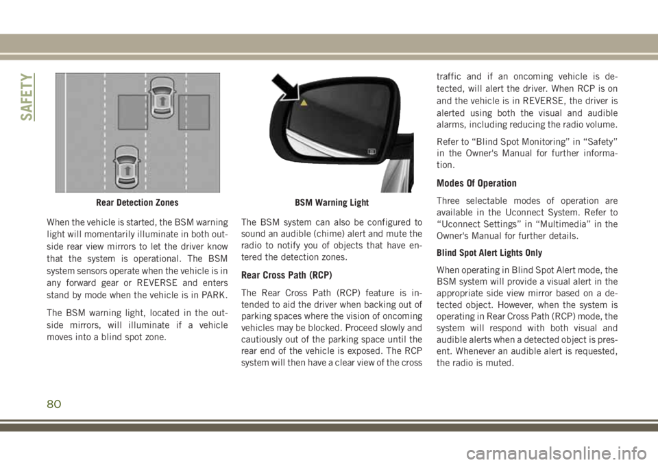
When the vehicle is started, the BSM warning
light will momentarily illuminate in both out-
side rear view mirrors to let the driver know
that the system is operational. The BSM
system sensors operate when the vehicle is in
any forward gear or REVERSE and enters
stand by mode when the vehicle is in PARK.
The BSM warning light, located in the out-
side mirrors, will illuminate if a vehicle
moves into a blind spot zone.The BSM system can also be configured to
sound an audible (chime) alert and mute the
radio to notify you of objects that have en-
tered the detection zones.
Rear Cross Path (RCP)
The Rear Cross Path (RCP) feature is in-
tended to aid the driver when backing out of
parking spaces where the vision of oncoming
vehicles may be blocked. Proceed slowly and
cautiously out of the parking space until the
rear end of the vehicle is exposed. The RCP
system will then have a clear view of the cross traffic and if an oncoming vehicle is de-
tected, will alert the driver. When RCP is on
and the vehicle is in REVERSE, the driver is
alerted using both the visual and audible
alarms, including reducing the radio volume.
Refer to “Blind Spot Monitoring” in “Safety”
in the Owner's Manual for further informa-
tion.
Modes Of Operation
Three selectable modes of operation are
available in the Uconnect System. Refer to
“Uconnect Settings” in “Multimedia” in the
Owner's Manual for further details.
Blind Spot Alert Lights Only
When operating in Blind Spot Alert mode, the
BSM system will provide a visual alert in the
appropriate side view mirror based on a de-
tected object. However, when the system is
operating in Rear Cross Path (RCP) mode, the
system will respond with both visual and
audible alerts when a detected object is pres-
ent. Whenever an audible alert is requested,
the radio is muted.Rear Detection ZonesBSM Warning Light
SAFETY
80
Page 83 of 312
Blind Spot Alert Lights/Chime
When operating in Blind Spot Alert Lights/
Chime mode, the BSM system will provide a
visual alert in the appropriate side view mirror
based on a detected object. If the turn signal
is then activated, and it corresponds to an
alert present on that side of the vehicle, an
audible chime will also be sounded. When-
ever a turn signal and detected object are
present on the same side at the same time,
both the visual and audible alerts will be
issued. In addition to the audible alert, the
radio (if on) will also be muted.
NOTE:
Whenever an audible alert is requested by the
BSM system, the radio is also muted.
When the system is in RCP, the system shall
respond with both visual and audible alerts
when a detected object is present. Whenever
an audible alert is requested, the radio is also
muted. Turn/hazard signal status is ignored;
the RCP state always requests the chime.Blind Spot Alert Off
When the BSM system is turned off, there will
be no visual or audible alerts from either the
BSM or RCP systems.
NOTE:
The BSM system will store the current oper-
ating mode when the vehicle is shut off. Each
time the vehicle is started the previously
stored mode will be recalled and used.
Forward Collision Warning (FCW)
The Forward Collision Warning (FCW) system
provides the driver with audible and visual
warnings within the instrument cluster display
to warn the driver when it detects a potential
frontal collision. The warnings are intended to
provide the driver with enough time to react,
avoid or mitigate the potential collision.
NOTE:
FCW monitors the information from the for-
ward looking sensors, as well as the Elec-
tronic Brake Controller (EBC), to calculate
the probability of a forward collision. When
the system determines that a forward colli-
sion is probable, the driver will be provided
with audible and visual warnings.Turning FCW On Or Off
The FCW button is located on the switch
panel below the Uconnect display.
• To turn the FCW system off, push the for-
ward collision button once to turn the sys-
tem OFF.
• To turn the FCW system back on, push the forward collision button again to turn the
system on.
NOTE:
• The default status of FCW is “on”, this allows the system to warn you of a possible
collision with the vehicle in front of you.
• Changing the FCW status to “off” prevents the system from warning you of a possible
collision with the vehicle in front of you. If
FCW is set to off, “FCW OFF” will appear in
the instrument cluster display.
Changing FCW Status
The FCW feature has two settings and can be
changed within the Uconnect System
Screen:
• Far
• Near
81
Page 85 of 312
The TPMS will warn the driver of a low tire
pressure if the tire pressure falls below the
low-pressure warning limit for any reason,
including low temperature effects and natu-
ral pressure loss through the tire.
The TPMS will continue to warn the driver of
low tire pressure as long as the condition
exists, and will not turn off until the tire
pressure is at or above the recommended
cold placard pressure. Once the low tire pres-
sure warning (Tire Pressure Monitoring Tell-
tale Light) illuminates, you must increase the
tire pressure to the recommended cold plac-
ard pressure in order for the “Tire Pressure
Monitoring Telltale Light” to turn off.
NOTE:
When filling warm tires, the tire pressure may
need to be increased up to an additional 4 psi
(28 kPa) above the recommended cold plac-
ard pressure in order to turn the Tire Pressure
Monitoring Telltale Light off.
The system will automatically update and the
“Tire Pressure Monitoring Telltale Light” will
turn off once the system receives the updatedtire pressures. The vehicle may need to be
driven for up to 10 minutes above 15 mph
(24 km/h) in order for the TPMS to receive
this information.
For example, your vehicle may have a recom-
mended cold (parked for more than three
hours) placard pressure of 33 psi (227 kPa).
If the ambient temperature is 68°F (20°C)
and the measured tire pressure is 28 psi
(193 kPa), a temperature drop to 20°F (-7°C)
will decrease the tire pressure to approxi-
mately 24 psi (165 kPa). This tire pressure is
low enough to turn ON the “Tire Pressure
Monitoring Telltale Light.” Driving the vehicle
may cause the tire pressure to rise to approxi-
mately 28 psi (193 kPa), but the “Tire Pres-
sure Monitoring Telltale Light” will still be on.
In this situation, the “Tire Pressure Monitor-
ing Telltale Light” will turn off only after the
tires are inflated to the vehicle’s recom-
mended cold placard pressure value.
NOTE:
When filling warm tires, the tire pressure may
need to be increased up to an additional 4 psi
(28 kPa) above the recommended cold plac-
ard pressure in order to turn the Tire Pressure
Monitoring Telltale Light off.
CAUTION!
• The TPMS has been optimized for the
original equipment tires and wheels.
TPMS pressures and warning have been
established for the tire size equipped on
your vehicle. Undesirable system opera-
tion or sensor damage may result when
using replacement equipment that is not
of the same size, type, and/or style. The
TPM sensor is not designed for use on
aftermarket wheels, and may contribute
to a poor overall system performance.
Customers are encouraged to use OEM
wheels to assure TPMS feature opera-
tion.
• Using aftermarket tire sealants may
cause the Tire Pressure Monitoring Sys-
tem (TPMS) sensor to become inoper-
able. After using an aftermarket tire
83
Page 86 of 312
CAUTION!
sealant it is recommended that you take
your vehicle to an authorized dealer to
have your sensor function checked.
• After inspecting or adjusting the tire
pressure always reinstall the valve stem
cap. This will prevent moisture and dirt
from entering the valve stem, which
could damage the TPMS sensor.
NOTE:
• The TPMS is not intended to replace nor- mal tire care and maintenance, or to pro-
vide warning of a tire failure or condition.
• The TPMS should not be used as a tire pressure gauge while adjusting your tire
pressure.
• Driving on a significantly underinflated tire causes the tire to overheat and can lead to
tire failure. Underinflation also reduces
fuel efficiency and tire tread life, and may
affect the vehicle’s handling and stopping
ability.
• The TPMS is not a substitute for proper tire maintenance, and it is the driver’s respon-
sibility to maintain correct tire pressure using an accurate tire pressure gauge, even
if underinflation has not reached the level
to trigger illumination of the “Tire Pressure
Monitoring Telltale Light”.
• Seasonal temperature changes will affect tire pressure, and the TPMS will monitor
the actual tire pressure in the tire.
Premium System
The Tire Pressure Monitor System (TPMS)
uses wireless technology with wheel rim
mounted electronic sensors to monitor tire
pressure levels. Sensors, mounted to each
wheel as part of the valve stem, transmit tire
pressure readings to the receiver module.
NOTE:
It is particularly important for you to check
the tire pressure in all of the tires on your
vehicle monthly and to maintain the proper
pressure.
The TPMS consists of the following compo-
nents:
• Receiver module
• Four tire pressure monitoring sensors • Various tire pressure monitoring system
messages, which display in the instrument
cluster
• Tire Pressure Monitoring System Warning Light
Tire Pressure Monitoring Low Pressure Warnings
The “Tire Pressure Monitoring
Telltale Light” will illuminate in
the instrument cluster and a
chime will sound when tire pres-
sure is low in one or more of the
four active road tires. In addition, the instru-
ment cluster will display a "Tire Low" mes-
sage for a minimum of five seconds and a
graphic showing the pressure values of each
tire with the low tire pressure values in a
different color.
SAFETY
84
Page 87 of 312
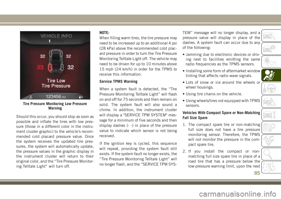
Should this occur, you should stop as soon as
possible and inflate the tires with low pres-
sure (those in a different color in the instru-
ment cluster graphic) to the vehicle’s recom-
mended cold placard pressure value. Once
the system receives the updated tire pres-
sures, the system will automatically update,
the pressure values in the graphic display in
the instrument cluster will return to their
original color, and the “Tire Pressure Monitor-
ing Telltale Light” will turn off.NOTE:
When filling warm tires, the tire pressure may
need to be increased up to an additional 4 psi
(28 kPa) above the recommended cold plac-
ard pressure in order to turn the Tire Pressure
Monitoring Telltale Light off. The vehicle may
need to be driven for up to 10 minutes above
15 mph (24 km/h) in order for the TPMS to
receive this information.
Service TPMS Warning
When a system fault is detected, the “Tire
Pressure Monitoring Telltale Light” will flash
on and off for 75 seconds and then remain on
solid. The system fault will also sound a
chime. In addition, the instrument cluster
will display a "SERVICE TPM SYSTEM" mes-
sage for a minimum of five seconds and then
display dashes (- -) in place of the pressure
value to indicate which sensor is not being
received.
If the ignition key is cycled, this sequence
will repeat, providing the system fault still
exists. If the system fault no longer exists, the
“Tire Pressure Monitoring Telltale Light” will
no longer flash, and the “SERVICE TPM SYS-
TEM” message will no longer display, and a
pressure value will display in place of the
dashes. A system fault can occur due to any
of the following:
• Jamming due to electronic devices or driv-
ing next to facilities emitting the same
radio frequencies as the TPMS sensors.
• Installing some form of aftermarket window tinting that affects radio wave signals.
• Lots of snow or ice around the wheels or wheel housings.
• Using tire chains on the vehicle.
• Using wheels/tires not equipped with TPMS sensors.
Vehicles With Compact Spare or Non-Matching
Full Size Spare
1. The compact spare tire or non-matching full size does not have a tire pressure
monitoring sensor. Therefore, the TPMS
will not monitor the pressure in the com-
pact spare tire.
2. If you install the compact or non- matching full size spare tire in place of a
road tire that has a pressure below the
low-pressure warning limit, upon the next
Tire Pressure Monitoring Low Pressure Warning
85