JEEP CHEROKEE 2018 Owner handbook (in English)
Manufacturer: JEEP, Model Year: 2018, Model line: CHEROKEE, Model: JEEP CHEROKEE 2018Pages: 312, PDF Size: 4.91 MB
Page 51 of 312
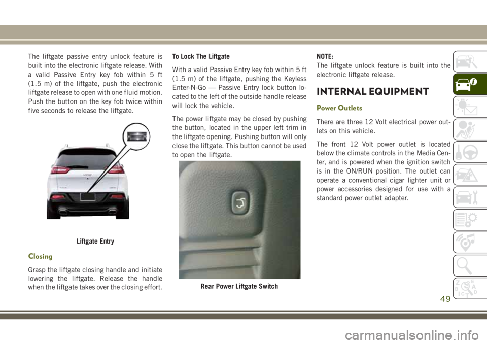
The liftgate passive entry unlock feature is
built into the electronic liftgate release. With
a valid Passive Entry key fob within 5 ft
(1.5 m) of the liftgate, push the electronic
liftgate release to open with one fluid motion.
Push the button on the key fob twice within
five seconds to release the liftgate.
Closing
Grasp the liftgate closing handle and initiate
lowering the liftgate. Release the handle
when the liftgate takes over the closing effort.To Lock The Liftgate
With a valid Passive Entry key fob within 5 ft
(1.5 m) of the liftgate, pushing the Keyless
Enter-N-Go — Passive Entry lock button lo-
cated to the left of the outside handle release
will lock the vehicle.
The power liftgate may be closed by pushing
the button, located in the upper left trim in
the liftgate opening. Pushing button will only
close the liftgate. This button cannot be used
to open the liftgate.
NOTE:
The liftgate unlock feature is built into the
electronic liftgate release.
INTERNAL EQUIPMENT
Power Outlets
There are three 12 Volt electrical power out-
lets on this vehicle.
The front 12 Volt power outlet is located
below the climate controls in the Media Cen-
ter, and is powered when the ignition switch
is in the ON/RUN position. The outlet can
operate a conventional cigar lighter unit or
power accessories designed for use with a
standard power outlet adapter.
Liftgate Entry
Rear Power Liftgate Switch
49
Page 52 of 312
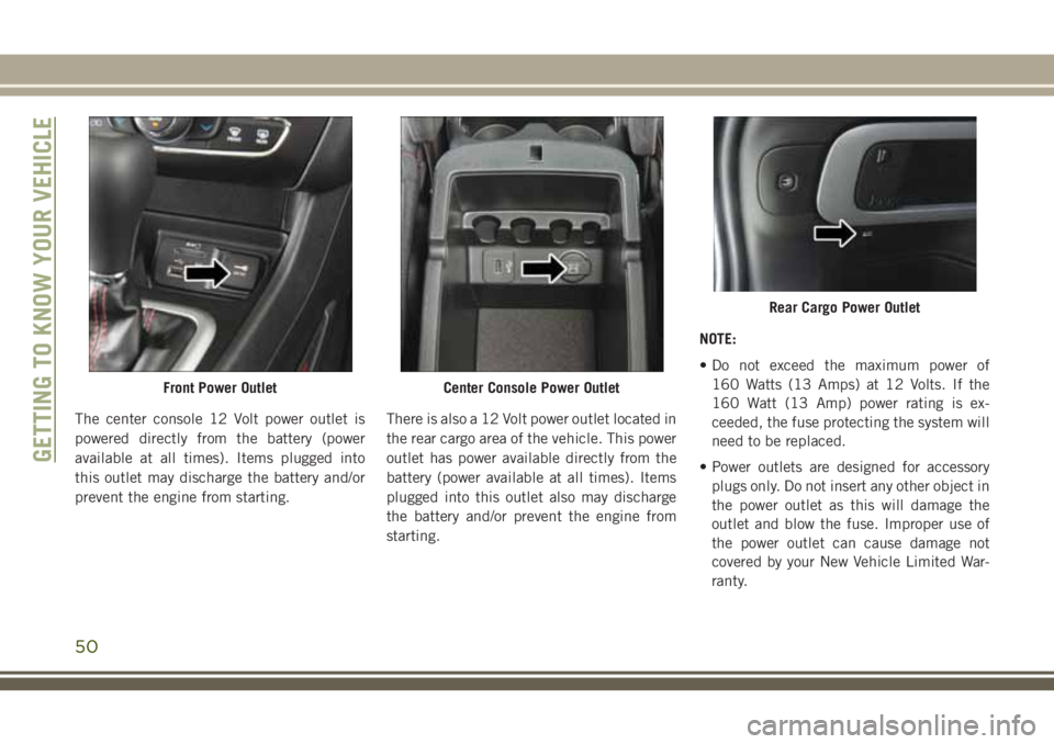
The center console 12 Volt power outlet is
powered directly from the battery (power
available at all times). Items plugged into
this outlet may discharge the battery and/or
prevent the engine from starting.There is also a 12 Volt power outlet located in
the rear cargo area of the vehicle. This power
outlet has power available directly from the
battery (power available at all times). Items
plugged into this outlet also may discharge
the battery and/or prevent the engine from
starting. NOTE:
• Do not exceed the maximum power of
160 Watts (13 Amps) at 12 Volts. If the
160 Watt (13 Amp) power rating is ex-
ceeded, the fuse protecting the system will
need to be replaced.
• Power outlets are designed for accessory plugs only. Do not insert any other object in
the power outlet as this will damage the
outlet and blow the fuse. Improper use of
the power outlet can cause damage not
covered by your New Vehicle Limited War-
ranty.
Front Power OutletCenter Console Power Outlet
Rear Cargo Power Outlet
GETTING TO KNOW YOUR VEHICLE
50
Page 53 of 312
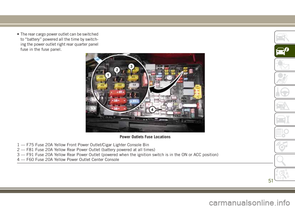
• The rear cargo power outlet can be switchedto “battery” powered all the time by switch-
ing the power outlet right rear quarter panel
fuse in the fuse panel.
Power Outlets Fuse Locations
1 — F75 Fuse 20A Yellow Front Power Outlet/Cigar Lighter Console Bin
2 — F81 Fuse 20A Yellow Rear Power Outlet (battery powered at all times)
3 — F91 Fuse 20A Yellow Rear Power Outlet (powered when the ignition switch is in the ON or ACC position)
4 — F60 Fuse 20A Yellow Power Outlet Center Console
51
Page 54 of 312
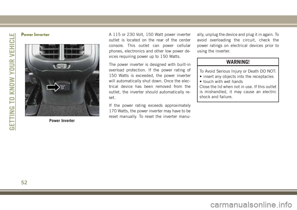
Power InverterA 115 or 230 Volt, 150 Watt power inverter
outlet is located on the rear of the center
console. This outlet can power cellular
phones, electronics and other low power de-
vices requiring power up to 150 Watts.
The power inverter is designed with built-in
overload protection. If the power rating of
150 Watts is exceeded, the power inverter
will automatically shut down. Once the elec-
trical device has been removed from the
outlet, the inverter should automatically re-
set.
If the power rating exceeds approximately
170 Watts, the power inverter may have to be
reset manually. To reset the inverter manu-ally, unplug the device and plug it in again. To
avoid overloading the circuit, check the
power ratings on electrical devices prior to
using the inverter.
WARNING!
To Avoid Serious Injury or Death DO NOT:
• insert any objects into the receptacles
• touch with wet hands
Close the lid when not in use. If this outlet
is mishandled, it may cause an electric
shock and failure.
Power Inverter
GETTING TO KNOW YOUR VEHICLE
52
Page 55 of 312
GETTING TO KNOW YOUR INSTRUMENT PANEL
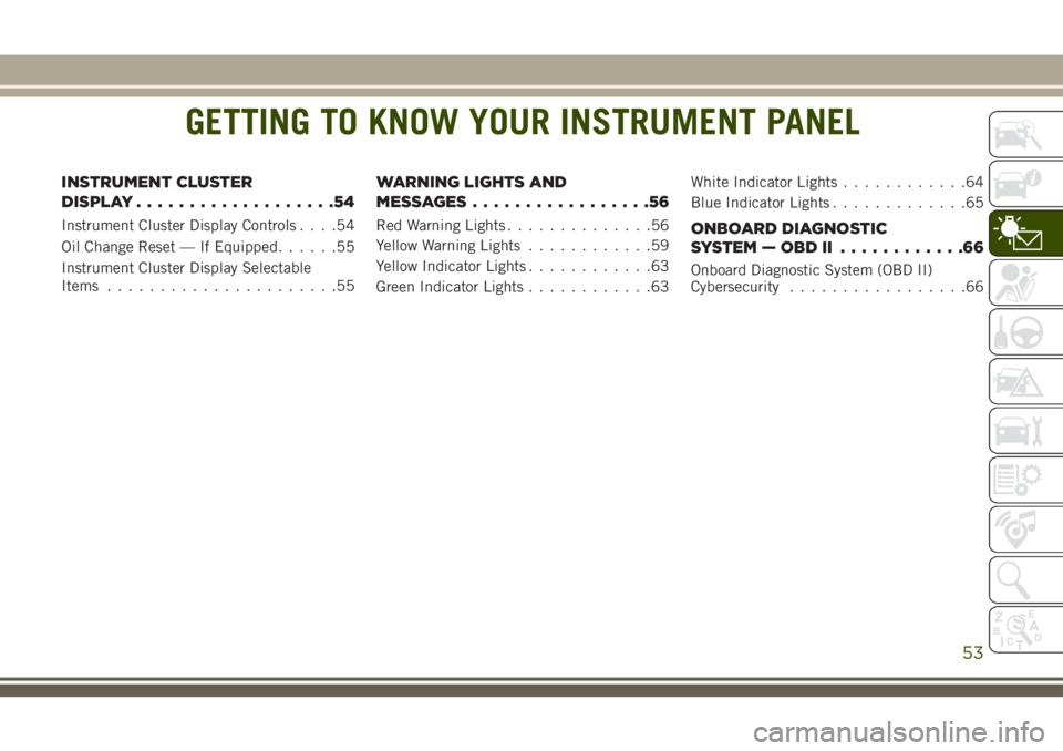
INSTRUMENT CLUSTER
DISPLAY...................54
Instrument Cluster Display Controls ....54
Oil Change Reset — If Equipped ......55
Instrument Cluster Display Selectable
Items ......................55
WARNING LIGHTS AND
MESSAGES.................56
Red Warning Lights ..............56
Yellow Warning Lights ............59
Yellow Indicator Lights ............63
Green Indicator Lights ............63 White Indicator Lights
............64
Blue Indicator Lights .............65ONBOARD DIAGNOSTIC
SYSTEM—OBDII ............66
Onboard Diagnostic System (OBD II)
Cybersecurity.................66
GETTING TO KNOW YOUR INSTRUMENT PANEL
53
Page 56 of 312
INSTRUMENT CLUSTER
DISPLAY
Your vehicle may be equipped with an instru-
ment cluster display, which offers useful in-
formation to the driver. With the ignition in
the STOP/OFF mode, opening/closing of a
door will activate the display for viewing, and
display the total miles, or kilometers, in the
odometer. Your instrument cluster display is
designed to display important information
about your vehicle’s systems and features.
Using a driver interactive display located on
the instrument panel, your instrument clus-
ter display can show you how systems are
working and give you warnings when they
aren’t. The steering wheel mounted controls
allow you to scroll through and enter the main
menus and submenus. You can access the
specific information you want and make se-
lections and adjustments.
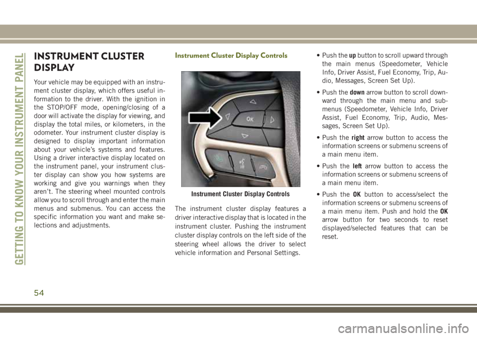
Instrument Cluster Display Controls
The instrument cluster display features a
driver interactive display that is located in the
instrument cluster. Pushing the instrument
cluster display controls on the left side of the
steering wheel allows the driver to select
vehicle information and Personal Settings.• Push the
upbutton to scroll upward through
the main menus (Speedometer, Vehicle
Info, Driver Assist, Fuel Economy, Trip, Au-
dio, Messages, Screen Set Up).
• Push the downarrow button to scroll down-
ward through the main menu and sub-
menus (Speedometer, Vehicle Info, Driver
Assist, Fuel Economy, Trip, Audio, Mes-
sages, Screen Set Up).
• Push the rightarrow button to access the
information screens or submenu screens of
a main menu item.
• Push the leftarrow button to access the
information screens or submenu screens of
a main menu item.
• Push the OKbutton to access/select the
information screens or submenu screens of
a main menu item. Push and hold the OK
arrow button for two seconds to reset
displayed/selected features that can be
reset.
Instrument Cluster Display Controls
GETTING TO KNOW YOUR INSTRUMENT PANEL
54
Page 57 of 312
Oil Change Reset — If Equipped
Your vehicle is equipped with an engine oil
change indicator system. The “Oil Change
Required” message will display in the instru-
ment cluster display for five seconds after a
single chime has sounded to indicate the
next scheduled oil change interval. The en-
gine oil change indicator system is duty cycle
based, which means the engine oil change
interval may fluctuate, dependent upon your
personal driving style.
Unless reset, this message will continue to
display each time you cycle the ignition to the
ON/RUN position. To turn off the message
temporarily, push and release theOKbutton.
To reset the oil change indicator system (after
performing the scheduled maintenance), re-
fer to the following procedure.
Oil Life Reset
1. Without pushing the brake pedal, push and release the ENGINE START/STOP
button and place the ignition to the ON/
RUN position (do not start the engine). 2. Navigate to "Oil Life" submenu in "Vehicle
Info" in the instrument cluster display.
3. Push and hold the OKbutton until the
gauge resets to 100%.
Secondary Method For Oil Change Reset Proce-
dure
1. Without pushing the brake pedal, push and release the ENGINE START/STOP
button and place the ignition to the ON/
RUN position (do not start the engine).
2. Fully press the accelerator pedal, slowly, three times within ten seconds.
3. Without pushing the brake pedal, push and release the ENGINE START/STOP
button once to return the ignition to the
OFF/LOCK position.
NOTE:
If the indicator message illuminates when
you start the vehicle, the oil change indicator
system did not reset. If necessary, repeat this
procedure.
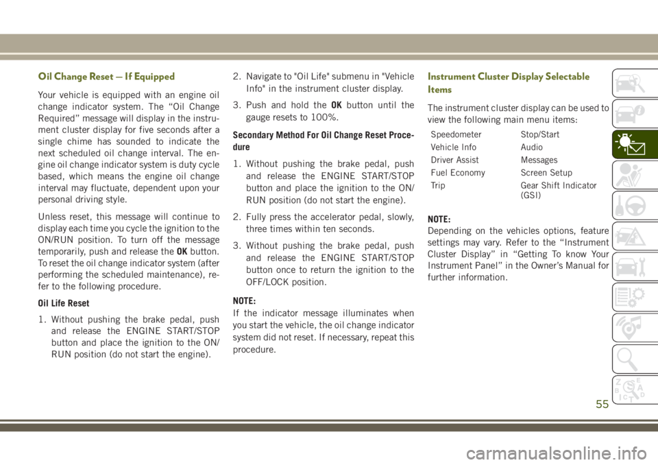
Instrument Cluster Display Selectable
Items
The instrument cluster display can be used to
view the following main menu items:
Speedometer Stop/Start
Vehicle Info Audio
Driver Assist Messages
Fuel Economy Screen Setup
Trip Gear Shift Indicator (GSI)
NOTE:
Depending on the vehicles options, feature
settings may vary. Refer to the “Instrument
Cluster Display” in “Getting To know Your
Instrument Panel” in the Owner’s Manual for
further information.
55
Page 58 of 312
WARNING LIGHTS AND
MESSAGES
The warning/indicator lights will illuminate in
the instrument panel together with a dedi-
cated message and/or acoustic signal when
applicable. These indications are indicative
and precautionary and as such must not be
considered as exhaustive and/or alternative
to the information contained in the Owner’s
Manual, which you are advised to read care-
fully in all cases. Always refer to the informa-
tion in this chapter in the event of a failure
indication. All active telltales will display first
if applicable. The system check menu may
appear different based upon equipment op-
tions and current vehicle status. Some tell-
tales are optional and may not appear.
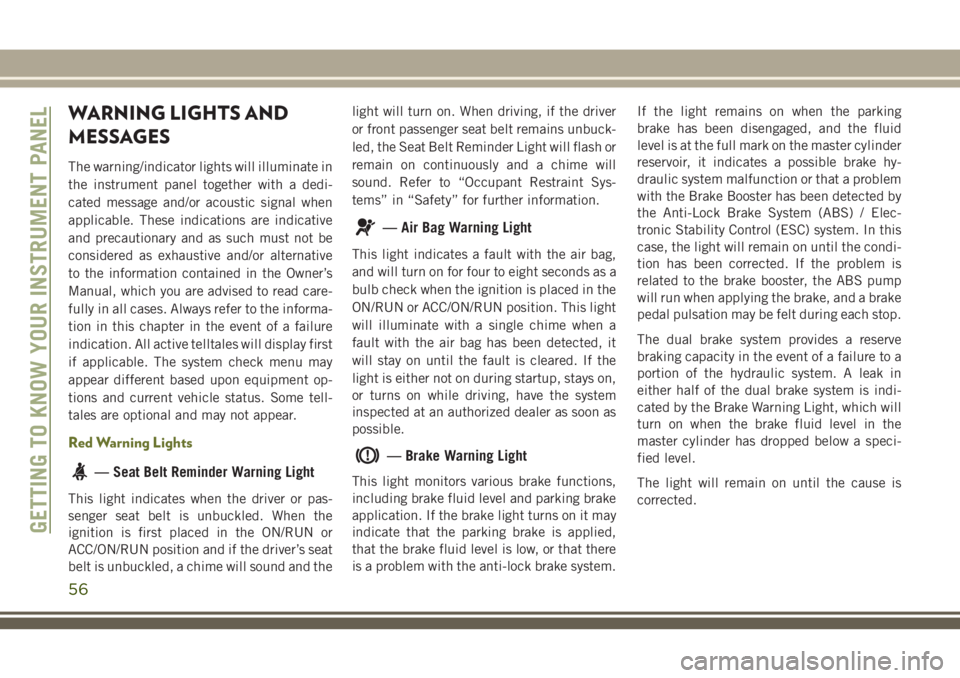
Red Warning Lights
— Seat Belt Reminder Warning Light
This light indicates when the driver or pas-
senger seat belt is unbuckled. When the
ignition is first placed in the ON/RUN or
ACC/ON/RUN position and if the driver’s seat
belt is unbuckled, a chime will sound and thelight will turn on. When driving, if the driver
or front passenger seat belt remains unbuck-
led, the Seat Belt Reminder Light will flash or
remain on continuously and a chime will
sound. Refer to “Occupant Restraint Sys-
tems” in “Safety” for further information.
— Air Bag Warning Light
This light indicates a fault with the air bag,
and will turn on for four to eight seconds as a
bulb check when the ignition is placed in the
ON/RUN or ACC/ON/RUN position. This light
will illuminate with a single chime when a
fault with the air bag has been detected, it
will stay on until the fault is cleared. If the
light is either not on during startup, stays on,
or turns on while driving, have the system
inspected at an authorized dealer as soon as
possible.
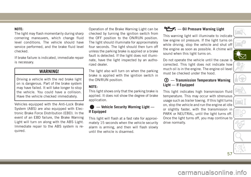
— Brake Warning Light
This light monitors various brake functions,
including brake fluid level and parking brake
application. If the brake light turns on it may
indicate that the parking brake is applied,
that the brake fluid level is low, or that there
is a problem with the anti-lock brake system.
If the light remains on when the parking
brake has been disengaged, and the fluid
level is at the full mark on the master cylinder
reservoir, it indicates a possible brake hy-
draulic system malfunction or that a problem
with the Brake Booster has been detected by
the Anti-Lock Brake System (ABS) / Elec-
tronic Stability Control (ESC) system. In this
case, the light will remain on until the condi-
tion has been corrected. If the problem is
related to the brake booster, the ABS pump
will run when applying the brake, and a brake
pedal pulsation may be felt during each stop.
The dual brake system provides a reserve
braking capacity in the event of a failure to a
portion of the hydraulic system. A leak in
either half of the dual brake system is indi-
cated by the Brake Warning Light, which will
turn on when the brake fluid level in the
master cylinder has dropped below a speci-
fied level.
The light will remain on until the cause is
corrected.
GETTING TO KNOW YOUR INSTRUMENT PANEL
56
Page 59 of 312
NOTE:
The light may flash momentarily during sharp
cornering maneuvers, which change fluid
level conditions. The vehicle should have
service performed, and the brake fluid level
checked.
If brake failure is indicated, immediate repair
is necessary.
WARNING!
Driving a vehicle with the red brake light
on is dangerous. Part of the brake system
may have failed. It will take longer to stop
the vehicle. You could have a collision.
Have the vehicle checked immediately.
Vehicles equipped with the Anti-Lock Brake
System (ABS) are also equipped with Elec-
tronic Brake Force Distribution (EBD). In the
event of an EBD failure, the Brake Warning
Light will turn on along with the ABS Light.
Immediate repair to the ABS system is re-
quired. Operation of the Brake Warning Light can be
checked by turning the ignition switch from
the OFF position to the ON/RUN position.
The light should illuminate for approximately
four seconds. The light should then turn off
unless the parking brake is applied or a brake
fault is detected. If the light does not illumi-
nate, have the light inspected by an autho-
rized dealer.
The light also will turn on when the parking
brake is applied with the ignition switch in
the ON/RUN position.
NOTE:
This light shows only that the parking brake is
applied. It does not show the degree of brake
application.
— Vehicle Security Warning Light —
If Equipped
This light will flash at a fast rate for approxi-
mately 15 seconds when the vehicle security
alarm is arming, and then will flash slowly
until the vehicle is disarmed.
— Oil Pressure Warning Light
This warning light will illuminate to indicate
low engine oil pressure. If the light turns on
while driving, stop the vehicle and shut off
the engine as soon as possible. A chime will
sound when this light turns on.
Do not operate the vehicle until the cause is
corrected. This light does not indicate how
much oil is in the engine. The engine oil level
must be checked under the hood.
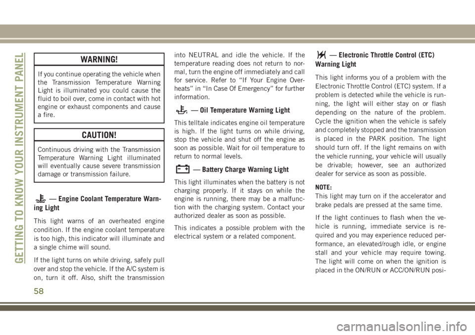
— Transmission Temperature Warning
Light — If Equipped
This light indicates high transmission fluid
temperature. This may occur with strenuous
usage such as trailer towing. If this light turns
on, stop the vehicle and run the engine at idle
or slightly faster, with the transmission in
PARK or NEUTRAL, until the light turns off.
Once the light turns off, you may continue to
drive normally.
57
Page 60 of 312
WARNING!
If you continue operating the vehicle when
the Transmission Temperature Warning
Light is illuminated you could cause the
fluid to boil over, come in contact with hot
engine or exhaust components and cause
a fire.
CAUTION!
Continuous driving with the Transmission
Temperature Warning Light illuminated
will eventually cause severe transmission
damage or transmission failure.
— Engine Coolant Temperature Warn-
ing Light
This light warns of an overheated engine
condition. If the engine coolant temperature
is too high, this indicator will illuminate and
a single chime will sound.
If the light turns on while driving, safely pull
over and stop the vehicle. If the A/C system is
on, turn it off. Also, shift the transmission into NEUTRAL and idle the vehicle. If the
temperature reading does not return to nor-
mal, turn the engine off immediately and call
for service. Refer to “If Your Engine Over-
heats” in “In Case Of Emergency” for further
information.
— Oil Temperature Warning Light
This telltale indicates engine oil temperature
is high. If the light turns on while driving,
stop the vehicle and shut off the engine as
soon as possible. Wait for oil temperature to
return to normal levels.
— Battery Charge Warning Light
This light illuminates when the battery is not
charging properly. If it stays on while the
engine is running, there may be a malfunc-
tion with the charging system. Contact your
authorized dealer as soon as possible.
This indicates a possible problem with the
electrical system or a related component.
— Electronic Throttle Control (ETC)
Warning Light
This light informs you of a problem with the
Electronic Throttle Control (ETC) system. If a
problem is detected while the vehicle is run-
ning, the light will either stay on or flash
depending on the nature of the problem.
Cycle the ignition when the vehicle is safely
and completely stopped and the transmission
is placed in the PARK position. The light
should turn off. If the light remains on with
the vehicle running, your vehicle will usually
be drivable; however, see an authorized
dealer for service as soon as possible.
NOTE:
This light may turn on if the accelerator and
brake pedals are pressed at the same time.
If the light continues to flash when the ve-
hicle is running, immediate service is re-
quired and you may experience reduced per-
formance, an elevated/rough idle, or engine
stall and your vehicle may require towing.
The light will come on when the ignition is
placed in the ON/RUN or ACC/ON/RUN posi-
GETTING TO KNOW YOUR INSTRUMENT PANEL
58