engine JEEP CHEROKEE 2019 Owner handbook (in English)
[x] Cancel search | Manufacturer: JEEP, Model Year: 2019, Model line: CHEROKEE, Model: JEEP CHEROKEE 2019Pages: 344, PDF Size: 6.35 MB
Page 33 of 344
STEERING WHEEL
Tilt/Telescoping Steering Column
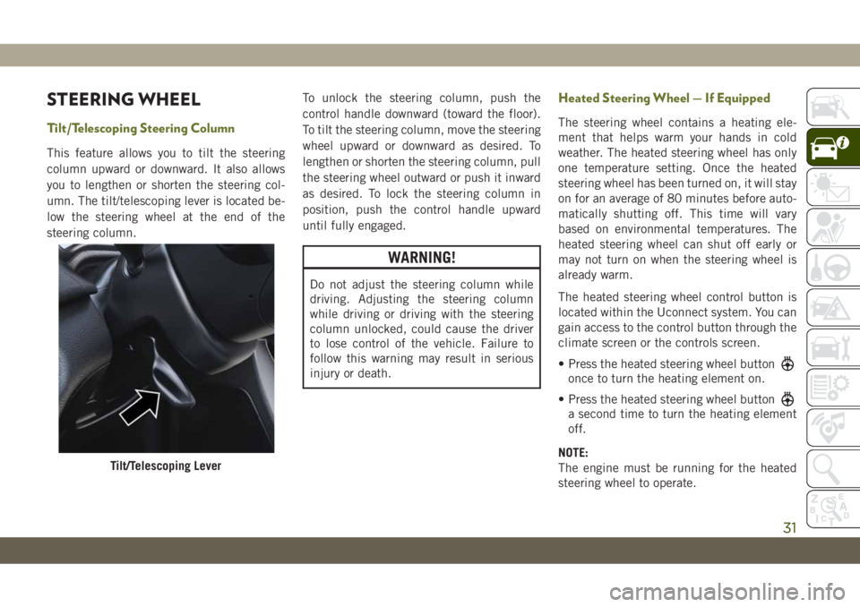
This feature allows you to tilt the steering
column upward or downward. It also allows
you to lengthen or shorten the steering col-
umn. The tilt/telescoping lever is located be-
low the steering wheel at the end of the
steering column.To unlock the steering column, push the
control handle downward (toward the floor).
To tilt the steering column, move the steering
wheel upward or downward as desired. To
lengthen or shorten the steering column, pull
the steering wheel outward or push it inward
as desired. To lock the steering column in
position, push the control handle upward
until fully engaged.
WARNING!
Do not adjust the steering column while
driving. Adjusting the steering column
while driving or driving with the steering
column unlocked, could cause the driver
to lose control of the vehicle. Failure to
follow this warning may result in serious
injury or death.
Heated Steering Wheel — If Equipped
The steering wheel contains a heating ele-
ment that helps warm your hands in cold
weather. The heated steering wheel has only
one temperature setting. Once the heated
steering wheel has been turned on, it will stay
on for an average of 80 minutes before auto-
matically shutting off. This time will vary
based on environmental temperatures. The
heated steering wheel can shut off early or
may not turn on when the steering wheel is
already warm.
The heated steering wheel control button is
located within the Uconnect system. You can
gain access to the control button through the
climate screen or the controls screen.
• Press the heated steering wheel button
once to turn the heating element on.
• Press the heated steering wheel button
a second time to turn the heating element
off.
NOTE:
The engine must be running for the heated
steering wheel to operate.
Tilt/Telescoping Lever
31
Page 35 of 344
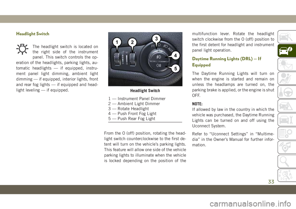
Headlight Switch
The headlight switch is located on
the right side of the instrument
panel. This switch controls the op-
eration of the headlights, parking lights, au-
tomatic headlights — if equipped, instru-
ment panel light dimming, ambient light
dimming — if equipped, interior lights, front
and rear fog lights — if equipped and head-
light leveling — if equipped.
From the O (off) position, rotating the head-
light switch counterclockwise to the first de-
tent will turn on the vehicle’s parking lights.
This feature will allow one side of the vehicle
parking lights to illuminate when the vehicle
is locked depending on the position of themultifunction lever. Rotate the headlight
switch clockwise from the O (off) position to
the first detent for headlight and instrument
panel light operation.
Daytime Running Lights (DRL) — If
Equipped
The Daytime Running Lights will turn on
when the engine is started and remain on
unless the headlamps are turned on, the
parking brake is applied, or the engine is shut
OFF.
NOTE:
If allowed by law in the country in which the
vehicle was purchased, the Daytime Running
Lights can be turned on and off using the
Uconnect System.
Refer to “Uconnect Settings” in “Multime-
dia” in the Owner’s Manual for further infor-
mation.
Headlight Switch
1 — Instrument Panel Dimmer
2 — Ambient Light Dimmer
3 — Rotate Headlight
4 — Push Front Fog Light
5 — Push Rear Fog Light
33
Page 36 of 344
High/Low Beam Switch
Push the multifunction lever, located on the
left side of the steering wheel, away from you
to switch the headlights to high beam. Pull
the multifunction lever toward you to switch
the headlights back to low beam.
Automatic High Beam Headlamp Control
— If Equipped
The Automatic High Beam Headlamp Control
system provides increased forward lighting at
night by automating high beam control
through the use of a digital camera mounted
on the inside rearview mirror. This camera
detects vehicle specific light and automati-
cally switches from high beams to low beams
until the approaching vehicle is out of view.NOTE:
• The multifunction lever must be in the high
beam position in order to activate the Au-
tomatic High Beams.
• The Automatic High Beam Headlamp Con-
trol can be turned on or off using the
Uconnect System. Refer to “Uconnect Set-
tings” in “Multimedia” in your Owner’s
Manual for further information.
When set to AUTO, the system automatically
turns the headlights on or off based on am-
bient light levels.
Flash-To-Pass
You can signal another vehicle with your
headlights by lightly pulling the multifunc-
tion lever toward you. This will cause the high
beam headlights to turn on, and remain on,
until the lever is released.
Automatic Headlights — If Equipped
This system automatically turns the head-
lights on or off according to ambient light
levels. To turn the system on, rotate the
headlight switch clockwise to the last detent
(AUTO position) for automatic headlight op-
eration. When the system is on, the headlight
time delay feature is also on. This means the
headlights will stay on for up to 90 seconds
after you place the ignition into the OFF
position. To turn the automatic system off,
move the headlight switch out of the AUTO
position.
NOTE:
The engine must be running before the head-
lights will come on in the automatic mode.
Parking Lights
To operate the parking lights, the ignition
must be in the OFF position. Turn the head-
light switch to the “P” position. Then move
the multifunction lever up or down to turn on
the left or right side parking lights.
GETTING TO KNOW YOUR VEHICLE
34
Page 50 of 344
(button on the touchscreen greyed out) if
conditions exist that could create fogging on
the inside of the windshield.
Automatic Temperature Control (ATC) —
If Equipped
Automatic Operation
1. Push the AUTO button on the faceplate,
or the AUTO button on the touchscreen on
the Automatic Temperature Control (ATC)
Panel.
2. Next, adjust the temperature you would
like the system to maintain by adjusting
the driver and passenger temperature
control buttons. Once the desired tem-
perature is displayed, the system will
achieve and automatically maintain that
comfort level.
3. When the system is set up for your comfort
level, it is not necessary to change the
settings. You will experience the greatest
efficiency by simply allowing the system
to function automatically.NOTE:
• It is not necessary to move the temperature
settings for cold or hot vehicles. The system
automatically adjusts the temperature,
mode, and blower speed to provide comfort
as quickly as possible.
• The temperature can be displayed in U.S.
or Metric units by selecting the US/Metric
customer-programmable feature. Refer to
the “Uconnect Settings” in “Multimedia”
in your Owner’s Manual for further
information.
To provide you with maximum comfort in the
Automatic mode during cold start-ups, the
blower fan will remain on low until the engine
warms up. The blower will increase in speed
and transition into Auto mode.
Manual Operation Override
This system offers a full complement of
manual override features. The AUTO symbol
in the front ATC display will be turned off
when the system is being used in the manual
mode.
Operating Tips
Summer Operation
The engine cooling system must be protected
with a high-quality antifreeze coolant to pro-
vide proper corrosion protection and to pro-
tect against engine overheating. OAT coolant
(conforming to MS.90032) is recommended.
Winter Operation
To ensure the best possible heater and de-
froster performance, make sure the engine
cooling system is functioning properly and
the proper amount, type, and concentration
of coolant is used. Use of the Air Recircula-
tion mode during Winter months is not rec-
ommended, because it may cause window
fogging.
Vacation/Storage
Before you store your vehicle, or keep it out of
service (i.e., vacation) for two weeks or more,
run the air conditioning system at idle for
about five minutes, in fresh air with the
blower setting on high. This will ensure ad-
GETTING TO KNOW YOUR VEHICLE
48
Page 56 of 344
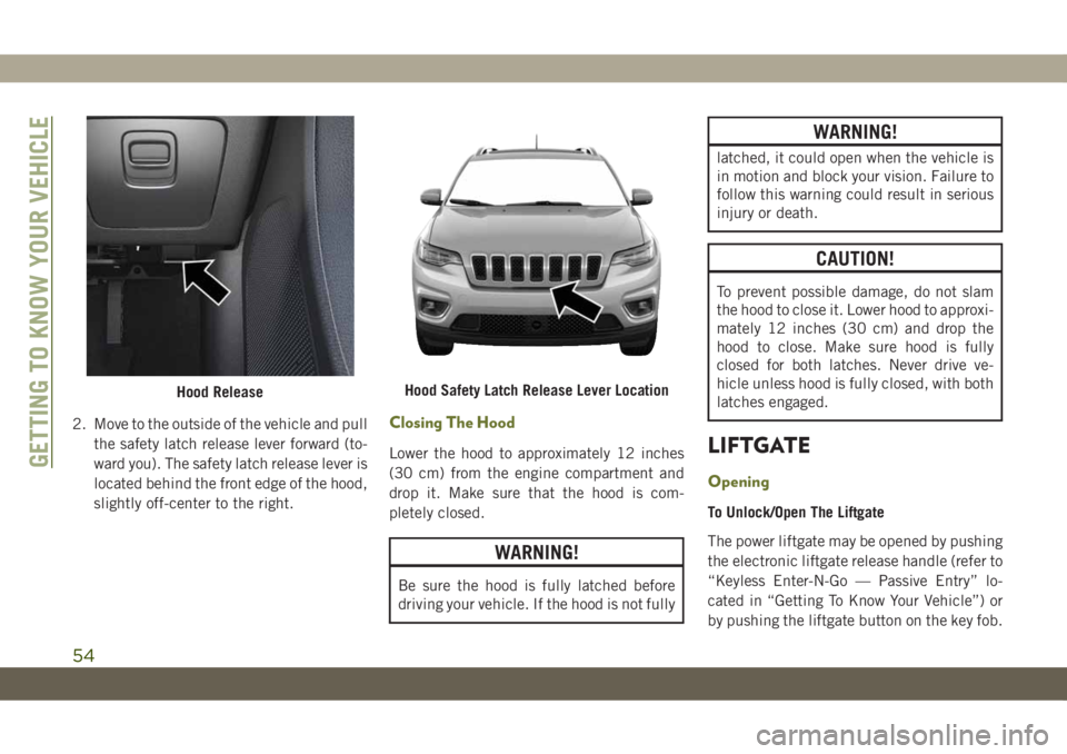
2. Move to the outside of the vehicle and pull
the safety latch release lever forward (to-
ward you). The safety latch release lever is
located behind the front edge of the hood,
slightly off-center to the right.Closing The Hood
Lower the hood to approximately 12 inches
(30 cm) from the engine compartment and
drop it. Make sure that the hood is com-
pletely closed.
WARNING!
Be sure the hood is fully latched before
driving your vehicle. If the hood is not fully
WARNING!
latched, it could open when the vehicle is
in motion and block your vision. Failure to
follow this warning could result in serious
injury or death.
CAUTION!
To prevent possible damage, do not slam
the hood to close it. Lower hood to approxi-
mately 12 inches (30 cm) and drop the
hood to close. Make sure hood is fully
closed for both latches. Never drive ve-
hicle unless hood is fully closed, with both
latches engaged.
LIFTGATE
Opening
To Unlock/Open The Liftgate
The power liftgate may be opened by pushing
the electronic liftgate release handle (refer to
“Keyless Enter-N-Go — Passive Entry” lo-
cated in “Getting To Know Your Vehicle”) or
by pushing the liftgate button on the key fob.
Hood ReleaseHood Safety Latch Release Lever Location
GETTING TO KNOW YOUR VEHICLE
54
Page 61 of 344
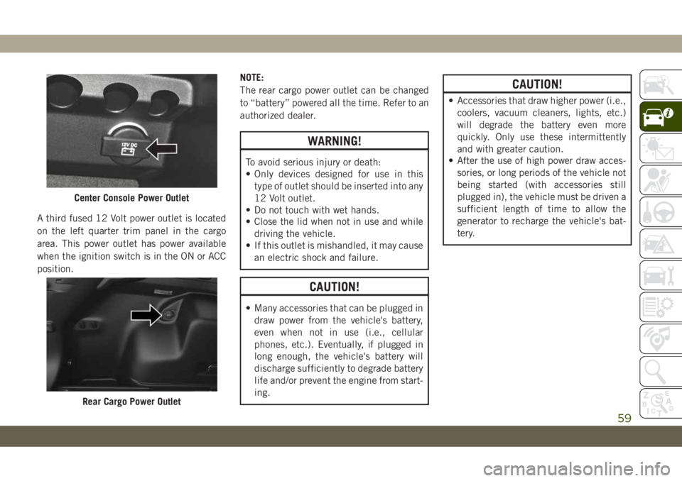
A third fused 12 Volt power outlet is located
on the left quarter trim panel in the cargo
area. This power outlet has power available
when the ignition switch is in the ON or ACC
position.NOTE:
The rear cargo power outlet can be changed
to “battery” powered all the time. Refer to an
authorized dealer.
WARNING!
To avoid serious injury or death:
• Only devices designed for use in this
type of outlet should be inserted into any
12 Volt outlet.
• Do not touch with wet hands.
• Close the lid when not in use and while
driving the vehicle.
• If this outlet is mishandled, it may cause
an electric shock and failure.
CAUTION!
• Many accessories that can be plugged in
draw power from the vehicle's battery,
even when not in use (i.e., cellular
phones, etc.). Eventually, if plugged in
long enough, the vehicle's battery will
discharge sufficiently to degrade battery
life and/or prevent the engine from start-
ing.
CAUTION!
• Accessories that draw higher power (i.e.,
coolers, vacuum cleaners, lights, etc.)
will degrade the battery even more
quickly. Only use these intermittently
and with greater caution.
• After the use of high power draw acces-
sories, or long periods of the vehicle not
being started (with accessories still
plugged in), the vehicle must be driven a
sufficient length of time to allow the
generator to recharge the vehicle's bat-
tery.
Center Console Power Outlet
Rear Cargo Power Outlet
59
Page 65 of 344
•Up Arrow Button
Push and release theuparrow button to
scroll upward through the main menu and
submenus.
•Down Arrow Button
Push and release thedownarrow button to
scroll downward through the main menu
and submenus.
•Right Arrow Button
Push and release therightarrow button to
access the information screens or submenu
screens of a main menu item.
•Left Arrow Button
Push and release theleftarrow button to
access the information screens or submenu
screens of a main menu item.
•OK Button
Push theOKbutton to access/select the
information screens or submenu screens of
a main menu item. Push and hold theOK
button to reset displayed/selected features
that can be reset.Instrument Cluster Display Selectable
Items
The instrument cluster display can be used to
view the following main menu items:
Speedometer Stop/Start
Vehicle Info Audio
Driver Assist Messages
Fuel Economy Screen Setup
Trip Gear Shift Indicator
(GSI)
NOTE:
Depending on the vehicles options, feature
settings may vary. Refer to the “Instrument
Cluster Display” in “Getting To know Your
Instrument Panel” in the Owner’s Manual for
further information.
Diesel Displays
When the appropriate conditions exist, the
following messages display in the instrument
cluster display:
• Exhaust Filter Nearing Full Safely Drive at
Consistent Speeds to Clear• Exhaust Filter Full – Power Reduced See
Dealer
• Exhaust System Service Required – See
Dealer
• Exhaust System – Filter XX% Full Service
Required See Dealer
• Exhaust System Regeneration in Process
Continue Driving
• Exhaust System – Regeneration Completed
Diesel Particulate Filter (DPF) Messages
This engine meets all required diesel engine
emissions standards. To achieve these emis-
sions standards, your vehicle is equipped
with a state-of-the-art engine and exhaust
system. These systems are seamlessly inte-
grated into your vehicle and managed by the
Powertrain Control Module (PCM). The PCM
manages engine combustion to allow the ex-
haust system’s catalyst to trap and burn Par-
ticulate Matter (PM) pollutants, with no input
or interaction on your part.
63
Page 66 of 344
WARNING!
A hot exhaust system can start a fire if you
park over materials that can burn. Such
materials might be grass or leaves coming
into contact with your exhaust system. Do
not park or operate your vehicle in areas
where your exhaust system can contact
anything that can burn.
CAUTION!
The engine may be switched off even if the
warning light is on: repeated interruptions
of the regeneration process could cause an
early deterioration of engine oil. For this
reason it is always advisable to wait for the
symbol to go off before turning off the
engine, following the instructions above.
Do not complete the DPF regeneration
process when the vehicle is stopped.
WARNING LIGHTS AND
MESSAGES
The warning/indicator lights will illuminate in
the instrument panel together with a dedi-
cated message and/or acoustic signal when
applicable. These indications are indicative
and precautionary and as such must not be
considered as exhaustive and/or alternative
to the information contained in the Owner’s
Manual, which you are advised to read care-
fully in all cases. Always refer to the informa-
tion in this chapter in the event of a failure
indication. All active telltales will display first
if applicable. The system check menu may
appear different based upon equipment op-
tions and current vehicle status. Some tell-
tales are optional and may not appear.
Red Warning Lights
— Seat Belt Reminder Warning Light
This warning light indicates when the driver
or passenger seat belt is unbuckled. When
the ignition is first placed in the ON/RUN or
ACC/ON/RUN position and if the driver’s seat
belt is unbuckled, a chime will sound and the
light will turn on. When driving, if the driver
or front passenger seat belt remains unbuck-
led, the Seat Belt Reminder Light will flash or
remain on continuously and a chime will
sound.
Refer to “Occupant Restraint Systems” in
“Safety” for further information.
— Air Bag Warning Light
This warning light will illuminate to indicate
a fault with the air bag, and will turn on for
four to eight seconds as a bulb check when
the ignition is placed in the ON/RUN or
ACC/ON/RUN position. This light will illumi-
nate with a single chime when a fault with the
air bag has been detected, it will stay on until
the fault is cleared. If the light is either not on
GETTING TO KNOW YOUR INSTRUMENT PANEL
64
Page 68 of 344
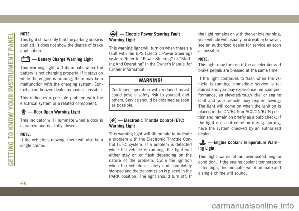
NOTE:
This light shows only that the parking brake is
applied. It does not show the degree of brake
application.
— Battery Charge Warning Light
This warning light will illuminate when the
battery is not charging properly. If it stays on
while the engine is running, there may be a
malfunction with the charging system. Con-
tact an authorized dealer as soon as possible.
This indicates a possible problem with the
electrical system or a related component.
— Door Open Warning Light
This indicator will illuminate when a door is
ajar/open and not fully closed.
NOTE:
If the vehicle is moving, there will also be a
single chime.
— Electric Power Steering Fault
Warning Light
This warning light will turn on when there's a
fault with the EPS (Electric Power Steering)
system. Refer to “Power Steering” in “Start-
ing And Operating” in the Owner’s Manual for
further information.
WARNING!
Continued operation with reduced assist
could pose a safety risk to yourself and
others. Service should be obtained as soon
as possible.
— Electronic Throttle Control (ETC)
Warning Light
This warning light will illuminate to indicate
a problem with the Electronic Throttle Con-
trol (ETC) system. If a problem is detected
while the vehicle is running, the light will
either stay on or flash depending on the
nature of the problem. Cycle the ignition
when the vehicle is safely and completely
stopped and the transmission is placed in the
PARK position. The light should turn off. Ifthe light remains on with the vehicle running,
your vehicle will usually be drivable; however,
see an authorized dealer for service as soon
as possible.
NOTE:
This light may turn on if the accelerator and
brake pedals are pressed at the same time.
If the light continues to flash when the ve-
hicle is running, immediate service is re-
quired and you may experience reduced per-
formance, an elevated/rough idle, or engine
stall and your vehicle may require towing.
The light will come on when the ignition is
placed in the ON/RUN or ACC/ON/RUN posi-
tion and remain on briefly as a bulb check. If
the light does not come on during starting,
have the system checked by an authorized
dealer.
— Engine Coolant Temperature Warn-
ing Light
This light warns of an overheated engine
condition. If the engine coolant temperature
is too high, this indicator will illuminate and
a single chime will sound.
GETTING TO KNOW YOUR INSTRUMENT PANEL
66
Page 69 of 344
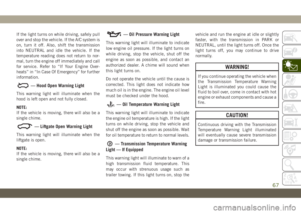
If the light turns on while driving, safely pull
over and stop the vehicle. If the A/C system is
on, turn it off. Also, shift the transmission
into NEUTRAL and idle the vehicle. If the
temperature reading does not return to nor-
mal, turn the engine off immediately and call
for service. Refer to “If Your Engine Over-
heats” in “In Case Of Emergency” for further
information.
— Hood Open Warning Light
This warning light will illuminate when the
hood is left open and not fully closed.
NOTE:
If the vehicle is moving, there will also be a
single chime.
— Liftgate Open Warning Light
This warning light will illuminate when the
liftgate is open.
NOTE:
If the vehicle is moving, there will also be a
single chime.
— Oil Pressure Warning Light
This warning light will illuminate to indicate
low engine oil pressure. If the light turns on
while driving, stop the vehicle, shut off the
engine as soon as possible, and contact an
authorized dealer. A chime will sound when
this light turns on.
Do not operate the vehicle until the cause is
corrected. This light does not indicate how
much oil is in the engine. The engine oil level
must be checked under the hood.
— Oil Temperature Warning Light
This warning light will illuminate to indicate
the engine oil temperature is high. If the light
turns on while driving, stop the vehicle and
shut off the engine as soon as possible. Wait
for oil temperature to return to normal levels.
— Transmission Temperature Warning
Light — If Equipped
This warning light will illuminate to warn of a
high transmission fluid temperature. This
may occur with strenuous usage such as
trailer towing. If this light turns on, stop thevehicle and run the engine at idle or slightly
faster, with the transmission in PARK or
NEUTRAL, until the light turns off. Once the
light turns off, you may continue to drive
normally.
WARNING!
If you continue operating the vehicle when
the Transmission Temperature Warning
Light is illuminated you could cause the
fluid to boil over, come in contact with hot
engine or exhaust components and cause a
fire.
CAUTION!
Continuous driving with the Transmission
Temperature Warning Light illuminated
will eventually cause severe transmission
damage or transmission failure.
67