engine JEEP CHEROKEE 2019 Owner handbook (in English)
[x] Cancel search | Manufacturer: JEEP, Model Year: 2019, Model line: CHEROKEE, Model: JEEP CHEROKEE 2019Pages: 344, PDF Size: 6.35 MB
Page 159 of 344
Refer to the “Stop/Start System” in the
“Starting And Operating” in your Owner’s
Manual.
Possible Reasons The Engine Does Not
Autostop
Prior to engine shut down, the system will
check many safety and comfort conditions to
see if they are fulfilled. Detailed information
about the operation of the Stop/Start system
may be viewed in the instrument cluster dis-
play Stop/Start Screen. In the following situ-
ations the engine will not stop:
• Driver’s seat belt is not buckled.
• Driver’s door is not closed.
• Battery temperature is too warm or cold.
• Battery charge is low.
• The vehicle is on a steep grade.
• Cabin heating or cooling is in process and
an acceptable cabin temperature has not
been achieved.
• HVAC is set to full defrost mode at a high
blower speed.
• HVAC set to MAX A/C.• Engine has not reached normal operating
temperature.
• The transmission is not in a forward or
reverse gear.
• Hood is open.
• Vehicle is in 4LO transfer case mode (if
equipped with 4WD).
• Brake pedal is not pressed with sufficient
pressure with vehicle in DRIVE position.
Other Factors Which Can Inhibit Autostop In-
clude:
• Accelerator pedal input.
• Engine temp too high.
• 5 mph threshold not achieved from previ-
ous AUTOSTOP.
• Steering angle beyond threshold.
• ACC is on and speed is set.
It may be possible for the vehicle to be driven
several times without the STOP/START sys-
tem going into a STOP/START READY state
under more extreme conditions of the items
listed above.
To Start The Engine While In Autostop
Mode
While in a forward gear, the engine will start
when the brake pedal is released or the
throttle pedal is depressed. The transmission
will automatically re-engage upon engine re-
start.
Conditions That Will Cause The Engine To Start
Automatically While In Autostop Mode:
• The transmission gear selector is moved out
of DRIVE except in the PARK position.
• To maintain cabin temperature comfort.
• HVAC is set to full defrost mode.
• HVAC system temperature or fan speed is
manually adjusted.
• Battery voltage drops too low.
• Low brake vacuum (e.g. after several brake
pedal applications).
• STOP/START OFF switch is pushed.
• A STOP/START system error occurs.
• 4WD system is put into 4LO mode (if
equipped with 4WD).
157
Page 160 of 344
Conditions That Force An Application Of The
Electric Park Brake While In Autostop Mode:
• The driver’s door is open and brake pedal
released.
• The driver’s door is open and the driver’s
seat belt is unbuckled.
• The engine hood has been opened.
• A STOP/START system error occurs.
If the Electric Park Brake is applied with the
engine off, the engine may require a manual
restart and the electric park brake may re-
quire a manual release (depress brake pedal
and push Electric Park Brake switch). Refer
to “Instrument Cluster Display” in “Getting
To Know Your Instrument Panel” in your Own-
er’s Manual.
To Manually Turn Off The Stop/Start
System
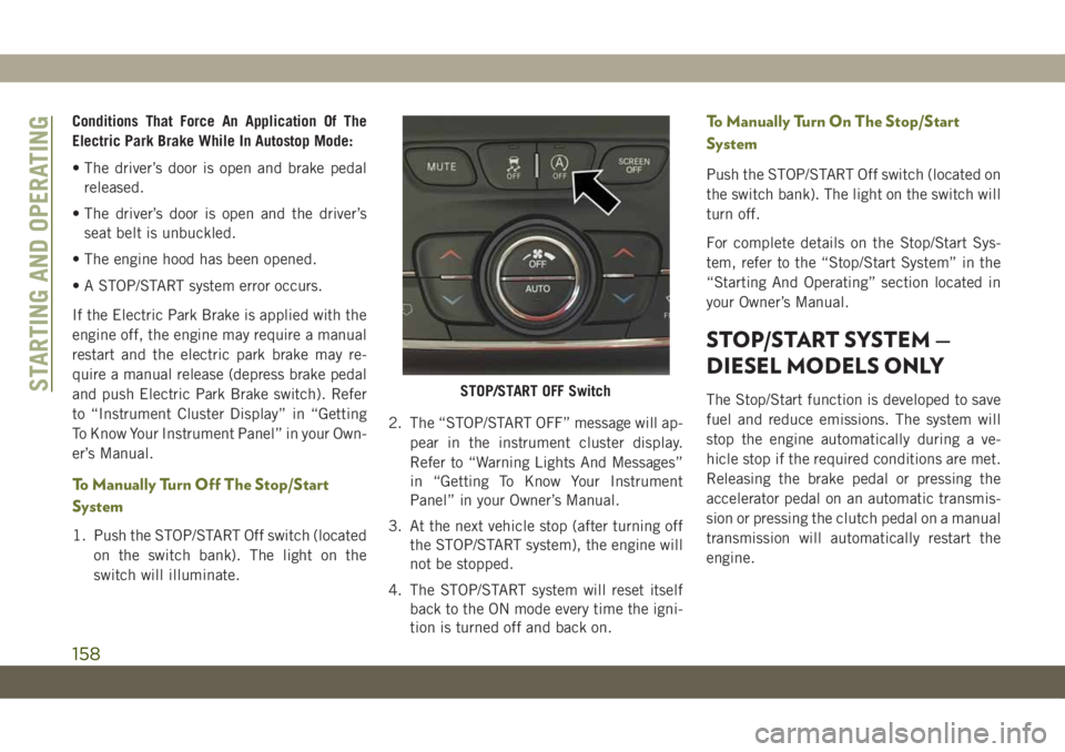
1. Push the STOP/START Off switch (located
on the switch bank). The light on the
switch will illuminate.2. The “STOP/START OFF” message will ap-
pear in the instrument cluster display.
Refer to “Warning Lights And Messages”
in “Getting To Know Your Instrument
Panel” in your Owner’s Manual.
3. At the next vehicle stop (after turning off
the STOP/START system), the engine will
not be stopped.
4. The STOP/START system will reset itself
back to the ON mode every time the igni-
tion is turned off and back on.
To Manually Turn On The Stop/Start
System
Push the STOP/START Off switch (located on
the switch bank). The light on the switch will
turn off.
For complete details on the Stop/Start Sys-
tem, refer to the “Stop/Start System” in the
“Starting And Operating” section located in
your Owner’s Manual.
STOP/START SYSTEM —
DIESEL MODELS ONLY
The Stop/Start function is developed to save
fuel and reduce emissions. The system will
stop the engine automatically during a ve-
hicle stop if the required conditions are met.
Releasing the brake pedal or pressing the
accelerator pedal on an automatic transmis-
sion or pressing the clutch pedal on a manual
transmission will automatically restart the
engine.STOP/START OFF SwitchSTARTING AND OPERATING
158
Page 161 of 344
Automatic Mode
The Stop/Start feature is enabled after every
normal customer engine start. It will remain
in STOP/START NOT READY until you drive
forward with a vehicle speed greater than
4 mph (7 km/h). At that time, the system will
go into STOP/START READY and if all other
conditions are met, can go into a STOP/
START AUTOSTOP ACTIVE “Autostop”
mode.
To Activate The Autostop Mode, The Following
Must Occur:
• The system must be in STOP/START
READY state. A STOP/START READY mes-
sage will be displayed in the instrument
cluster display within the Stop/Start sec-
tion. Refer to “Instrument Cluster Display”
in “Getting To Know Your Instrument
Panel” in your Owner’s information for fur-
ther details.
• The vehicle must be completely stopped.
• The gear selector must be in DRIVE and the
brake pedal depressed (automatic trans-
mission) or the gear selector must be in
NEUTRAL and the clutch pedal must be
fully released (manual transmission).The engine will shut down, the tachometer
will move to the zero position and the Stop/
Start telltale will illuminate indicating you
are in Autostop. While in Autostop, the Cli-
mate Controls system may automatically ad-
just airflow to maintain cabin comfort. Cus-
tomer settings will be maintained upon return
to an engine running condition.
Possible Reasons The Engine Does Not
Autostop
Prior to engine shut down, the system will
check many safety and comfort conditions to
see if they are fulfilled. Detailed information
about the operation of the Stop/Start system
may be viewed in the instrument cluster
Stop/Start Screen. In the following situations
the engine will not stop:
• Driver’s seat belt is not buckled.
• Driver’s door is not closed.
• Battery temperature is too warm or cold.
• The vehicle is on a steep grade.
• Cabin heating or cooling is in process and
an acceptable cabin temperature has not
been achieved.• HVAC is set to full defrost mode at a high
blower speed.
• Engine has not reached normal operating
temperature.
• Battery charge is low.
• The transmission is not in DRIVE (auto-
matic transmission) or NEUTRAL (manual
transmission).
• Hood is open.
• Vehicle is in 4LO transfer case mode.
• Exhaust system regeneration in process.
Other Factors Which Can Inhibit Autostop In-
clude:
• Fuel level.
• Accelerator pedal input (automatic trans-
mission only).
• Engine temperature too high.
It may be possible for the vehicle to be driven
several times without the STOP/START sys-
tem going into a STOP/START READY state
under more extreme conditions of the items
listed above.
159
Page 162 of 344
To Start The Engine While In Autostop
Mode
Automatic Transmission:
While in DRIVE, the engine will start when
the brake pedal is released or the throttle
pedal is depressed. The transmission will
automatically re-engage upon engine restart.
During this transition, the brakes will hold
the vehicle to avoid undesired vehicle move-
ment.
Manual Transmission:
When the gear selector is in NEUTRAL, the
engine will start when the clutch pedal is
pressed. The vehicle will go into STOP/
START SYSTEM NOT READY mode until the
vehicle speed is greater than 4 mph (7 km/h).
Conditions That Will Cause The Engine To Start
Automatically While In Autostop Mode:
• The transmission gear selector is moved
from DRIVE to REVERSE or NEUTRAL.
• To maintain cabin temperature comfort.
• HVAC is set to full defrost mode.
• Battery voltage drops too low.• Low brake vacuum (e.g. after several brake
pedal applications).
• STOP/START OFF switch is pushed.
• 4WD system is put into 4LO mode.
• The emissions system requires it.
• A STOP/START system error occurs.
• HVAC system temperature or fan speed is
manually adjusted.
Conditions That Force An Application Of The
Electric Park Brake While In Autostop Mode:
• The driver door is open and brake pedal
released.
• The driver door is open and the driver seat
belt is unbuckled.
• The engine hood has been opened.
• A STOP/START system error occurs.
If the Electric Park Brake is applied with the
engine off, the engine may require a manual
restart and the electric park brake may re-
quire a manual release (depress brake pedal
and push Electric Park Brake switch). Referto “Instrument Cluster Display” in “Getting
To Know Your Instrument Panel” in your Own-
er’s Manual for further information.To Manually Turn Off The Stop/Start
System
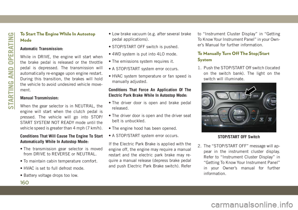
1. Push the STOP/START Off switch (located
on the switch bank). The light on the
switch will illuminate.
2. The “STOP/START OFF” message will ap-
pear in the instrument cluster display.
Refer to “Instrument Cluster Display” in
“Getting To Know Your Instrument Panel”
in your Owner’s manual for further
information.
STOP/START OFF Switch
STARTING AND OPERATING
160
Page 163 of 344
3. At the next vehicle stop (after turning off
the STOP/START system) the engine will
not be stopped.
4. If the STOP/START system is manually
turned off, the engine can only be started
and stopped by cycling the ignition
switch.
5. The STOP/START system will reset itself
back to an ON condition every time the
key is turned off and back on.
To Manually Turn On The Stop/Start
System
Push the STOP/START Off switch (located on
the switch bank). The light on the switch will
turn off.
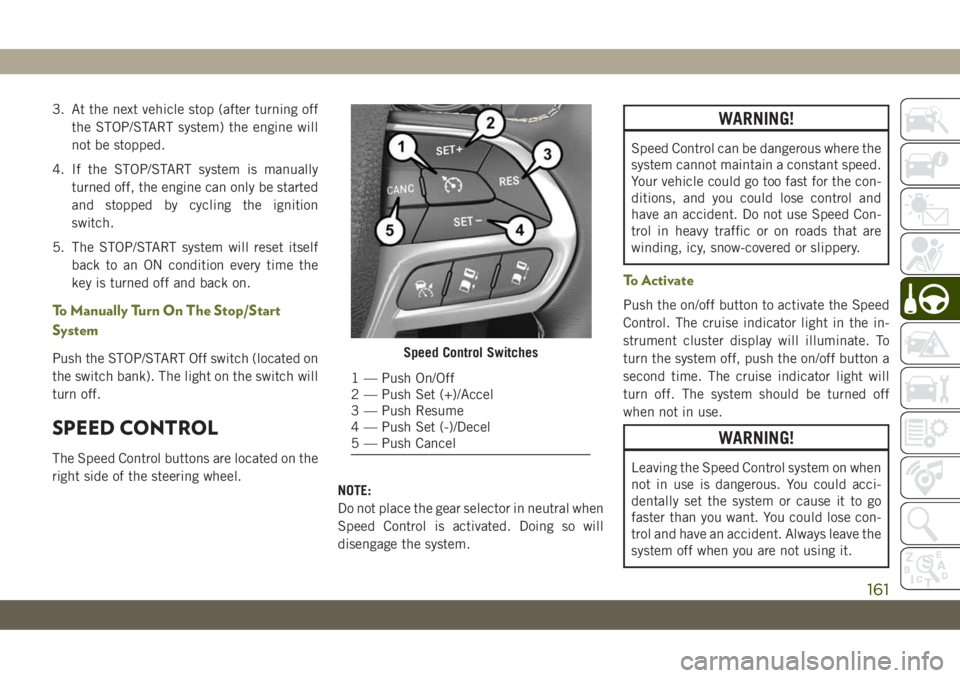
SPEED CONTROL
The Speed Control buttons are located on the
right side of the steering wheel.
NOTE:
Do not place the gear selector in neutral when
Speed Control is activated. Doing so will
disengage the system.
WARNING!
Speed Control can be dangerous where the
system cannot maintain a constant speed.
Your vehicle could go too fast for the con-
ditions, and you could lose control and
have an accident. Do not use Speed Con-
trol in heavy traffic or on roads that are
winding, icy, snow-covered or slippery.
To Activate
Push the on/off button to activate the Speed
Control. The cruise indicator light in the in-
strument cluster display will illuminate. To
turn the system off, push the on/off button a
second time. The cruise indicator light will
turn off. The system should be turned off
when not in use.
WARNING!
Leaving the Speed Control system on when
not in use is dangerous. You could acci-
dentally set the system or cause it to go
faster than you want. You could lose con-
trol and have an accident. Always leave the
system off when you are not using it.
Speed Control Switches
1 — Push On/Off
2 — Push Set (+)/Accel
3 — Push Resume
4 — Push Set (-)/Decel
5 — Push Cancel
161
Page 167 of 344
• If the button is continually pushed, the set
speed will continue to increase in 5 mph
increments until the button is released. The
increase in set speed is reflected in the
instrument cluster display.
Metric Speed (km/h)
• Pushing the SET(+)button once will result
in a 1 km/h increase in set speed. Each
subsequent tap of the button results in an
increase of 1 km/h.
• If the button is continually pushed, the set
speed will continue to increase in 10 km/h
increments until the button is released. The
increase in set speed is reflected in the
instrument cluster display.
To Decrease Speed
While ACC is set, the set speed can be de-
creased by pushing the SET(-)button.
The speed decrement shown is dependant on
the chosen speed unit of U.S. (mph) or Metric
(km/h):U.S. Speed (mph)
• Pushing the SET(-)button once will result
in a 1 mph decrease in set speed. Each
subsequent tap of the button results in a
decrease of 1 mph.
• If the button is continually pushed, the set
speed will continue to decrease in 5 mph
increments until the button is released. The
decrease in set speed is reflected in the
instrument cluster display.
Metric Speed (km/h)
• Pushing the SET(-)button once will result
in a 1 km/h decrease in set speed. Each
subsequent tap of the button results in a
decrease of 1 km/h.
• If the button is continually pushed, the set
speed will continue to decrease in 10 km/h
increments until the button is released. The
decrease in set speed is reflected in the
instrument cluster display.
NOTE:
• When you override and push the SET(+)
button or SET(-)buttons, the new set
speed will be the current speed of the
vehicle.• When you use the SET(-)button to decel-
erate, if the engine’s braking power does
not slow the vehicle sufficiently to reach
the set speed, the brake system will auto-
matically slow the vehicle.
• The ACC system decelerates the vehicle to
a full stop when following a target vehicle.
If an ACC host vehicle follows a target
vehicle to a standstill, after two seconds the
driver will either have to push the RES
(resume) button, or apply the accelerator
pedal to reengage the ACC to the existing
set speed.
• The ACC system maintains set speed when
driving up hill and down hill. However, a
slight speed change on moderate hills is
normal. In addition, downshifting may oc-
cur while climbing uphill or descending
downhill. This is normal operation and nec-
essary to maintain set speed. When driving
up hill and down hill, the ACC system will
cancel if the braking temperature exceeds
normal range (overheated).
165
Page 177 of 344
5. Remove funnel from filler pipe, clean off
prior to putting back in the spare tire
storage area.
NOTE:
• When the fuel nozzle “clicks” or shuts off,
the fuel tank is full.
WARNING!
• Never have any smoking materials lit in
or near the vehicle when the fuel door is
open or the tank is being filled.
• Never add fuel when the engine is run-
ning. This is in violation of most coun-
tries regulations and may cause the
“Malfunction Indicator Light” to turn
on.
• Do not apply any object/cap to the end of
the filler which is not provided for the
car. The use of non-compliant objects/
plugs could cause a pressure increase
inside the tank, resulting in dangerous
situations.
WARNING!
• A fire may result if fuel is pumped into a
portable container that is inside of a
vehicle. You could be burned. Always
place fuel containers on the ground
while filling.
REFUELING THE VEHICLE —
DIESEL ENGINE
The Capless Fuel System uses a flapper
placed at the filler pipe of the fuel tank; it
opens and closes automatically upon
insertion/extraction of the fuel nozzle. The
Capless Fuel System is designed so that it
prevents the filling of an incorrect type of
fuel.
1. Unlock the Fuel Filler Door by pushing the
unlock button on the key fob or the unlock
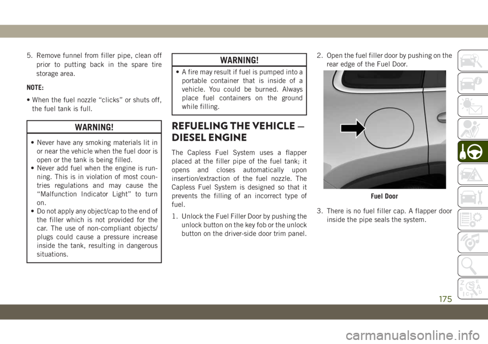
button on the driver-side door trim panel.2. Open the fuel filler door by pushing on the
rear edge of the Fuel Door.
3. There is no fuel filler cap. A flapper door
inside the pipe seals the system.
Fuel Door
175
Page 178 of 344
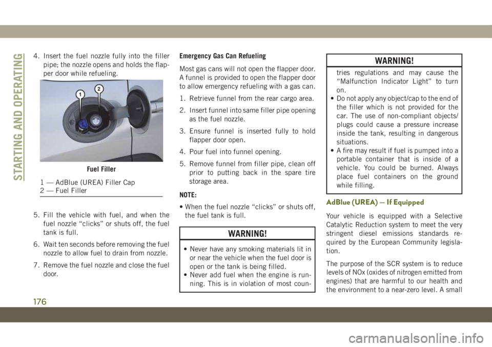
4. Insert the fuel nozzle fully into the filler
pipe; the nozzle opens and holds the flap-
per door while refueling.
5. Fill the vehicle with fuel, and when the
fuel nozzle “clicks” or shuts off, the fuel
tank is full.
6. Wait ten seconds before removing the fuel
nozzle to allow fuel to drain from nozzle.
7. Remove the fuel nozzle and close the fuel
door.Emergency Gas Can Refueling
Most gas cans will not open the flapper door.
A funnel is provided to open the flapper door
to allow emergency refueling with a gas can.
1. Retrieve funnel from the rear cargo area.
2. Insert funnel into same filler pipe opening
as the fuel nozzle.
3. Ensure funnel is inserted fully to hold
flapper door open.
4. Pour fuel into funnel opening.
5. Remove funnel from filler pipe, clean off
prior to putting back in the spare tire
storage area.
NOTE:
• When the fuel nozzle “clicks” or shuts off,
the fuel tank is full.
WARNING!
• Never have any smoking materials lit in
or near the vehicle when the fuel door is
open or the tank is being filled.
• Never add fuel when the engine is run-
ning. This is in violation of most coun-
WARNING!
tries regulations and may cause the
“Malfunction Indicator Light” to turn
on.
• Do not apply any object/cap to the end of
the filler which is not provided for the
car. The use of non-compliant objects/
plugs could cause a pressure increase
inside the tank, resulting in dangerous
situations.
• A fire may result if fuel is pumped into a
portable container that is inside of a
vehicle. You could be burned. Always
place fuel containers on the ground
while filling.
AdBlue (UREA) — If Equipped
Your vehicle is equipped with a Selective
Catalytic Reduction system to meet the very
stringent diesel emissions standards re-
quired by the European Community legisla-
tion.
The purpose of the SCR system is to reduce
levels of NOx (oxides of nitrogen emitted from
engines) that are harmful to our health and
the environment to a near-zero level. A small
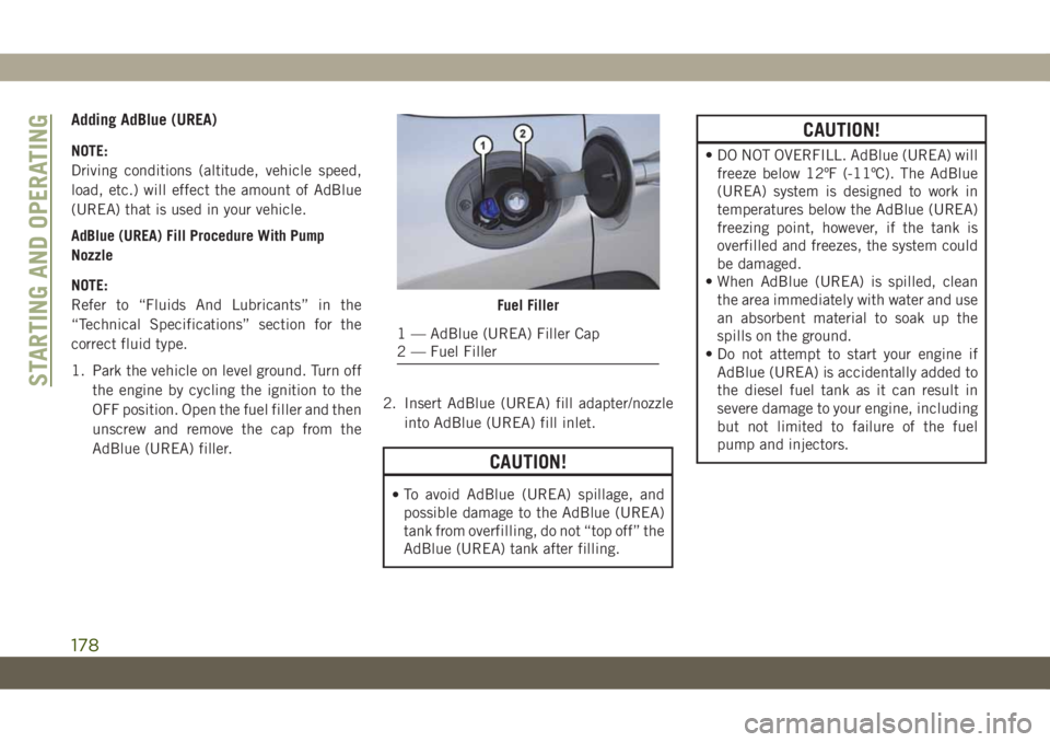
Fuel Filler
1 — AdBlue (UREA) Filler Cap
2 — Fuel FillerSTARTING AND OPERATING
176
Page 179 of 344
quantity AdBlue (UREA) is injected into the
exhaust upstream of a catalyst where, when
vaporized, it converts smog-forming nitrogen
oxides (NOx) into harmless nitrogen (N2) and
water vapor (H2O), two natural components
of the air we breathe. You can operate with
the comfort that your vehicle is contributing
to a cleaner, healthier world environment for
this and generations to come.
System Overview
This vehicle is equipped with a AdBlue
(UREA) injection system and a Selective
Catalytic Reduction (SCR) catalyst to meet
the emission requirements.
The AdBlue (UREA) injection system con-
sists of the following components:
• AdBlue (UREA) Tank
• AdBlue (UREA) Pump
• AdBlue (UREA) Injector
• Electronically-heated AdBlue (UREA)
Lines
• NOx sensors• Temperature sensors
• SCR catalyst
The AdBlue (UREA) injection system and
SCR catalyst enable the achievement of die-
sel emissions requirements; while maintain-
ing outstanding fuel economy, drivability,
torque and power ratings.
Refer to “Instrument Cluster Display” in
“Getting To Know Your Instrument Panel” for
system messages and warnings.
NOTE:
• Your vehicle is equipped with a AdBlue
(UREA) injection system. You may occa-
sionally hear an audible clicking noise from
under the vehicle at a stop. This is normal
operation.
• The AdBlue (UREA) pump will run for a
period of time after engine shutdown to
purge the AdBlue (UREA) system. This is
normal operation and may be audible from
the rear of the vehicle.
AdBlue (UREA) Storage
AdBlue (UREA) is considered a very stable
product with a long shelf life. If AdBlue
(UREA) is kept in temperatures between
10° and 90°F (-12° and 32°C), it will last a
minimum of one year.
AdBlue (UREA) is subject to freezing at the
lowest temperatures. For example, AdBlue
(UREA) may freeze at temperatures at or
below 12° F (-11° C). The system has been
designed to operate in this environment.
NOTE:
When working with AdBlue (UREA), it is
important to know that:
• Any containers or parts that come into con-
tact with AdBlue (UREA) must be AdBlue
(UREA) compatible (plastic or stainless
steel). Copper, brass, aluminum, iron or
non-stainless steel should be avoided as
they are subject to corrosion by AdBlue
(UREA).
• If AdBlue (UREA) is spilled, it should be
wiped up completely.
177
Page 180 of 344
Adding AdBlue (UREA)
NOTE:
Driving conditions (altitude, vehicle speed,
load, etc.) will effect the amount of AdBlue
(UREA) that is used in your vehicle.
AdBlue (UREA) Fill Procedure With Pump
Nozzle
NOTE:
Refer to “Fluids And Lubricants” in the
“Technical Specifications” section for the
correct fluid type.
1. Park the vehicle on level ground. Turn off
the engine by cycling the ignition to the
OFF position. Open the fuel filler and then
unscrew and remove the cap from the
AdBlue (UREA) filler.2. Insert AdBlue (UREA) fill adapter/nozzle
into AdBlue (UREA) fill inlet.
CAUTION!
•To avoid AdBlue (UREA) spillage, and
possible damage to the AdBlue (UREA)
tank from overfilling, do not “top off” the
AdBlue (UREA) tank after filling.
CAUTION!
• DO NOT OVERFILL. AdBlue (UREA) will
freeze below 12ºF (-11ºC). The AdBlue
(UREA) system is designed to work in
temperatures below the AdBlue (UREA)
freezing point, however, if the tank is
overfilled and freezes, the system could
be damaged.
• When AdBlue (UREA) is spilled, clean
the area immediately with water and use
an absorbent material to soak up the
spills on the ground.
• Do not attempt to start your engine if
AdBlue (UREA) is accidentally added to
the diesel fuel tank as it can result in
severe damage to your engine, including
but not limited to failure of the fuel
pump and injectors.
Fuel Filler
1 — AdBlue (UREA) Filler Cap
2 — Fuel Filler
STARTING AND OPERATING
178