engine JEEP CHEROKEE 2019 Owner handbook (in English)
[x] Cancel search | Manufacturer: JEEP, Model Year: 2019, Model line: CHEROKEE, Model: JEEP CHEROKEE 2019Pages: 344, PDF Size: 6.35 MB
Page 181 of 344
CAUTION!
• Never add anything other than AdBlue
(UREA) to the tank – especially any form
of hydrocarbon such as diesel fuel, fuel
system additives, gasoline, or any other
petroleum-based product. Even a very
small amount of these, less than
100 parts per million or less than 1 oz.
(30 ml) per 78 gallons (295 liters) will
contaminate the entire AdBlue (UREA)
system and will require replacement. If
owners use a container, funnel or nozzle
when refilling the tank, it should either
be new or one that is has only been used
for adding AdBlue (UREA). Mopar pro-
vides an attachable nozzle with its Ad-
Blue (UREA) for this purpose.3. Stop filling the AdBlue (UREA) tank im-
mediately when any of the following hap-
pen: AdBlue (UREA) splashes out the fill
inlet, or a AdBlue (UREA) pump nozzle
automatically shuts off.
4. After removing the nozzle, refit the cap on
the AdBlue (UREA) filler by turning it
clockwise until it is fully tightened. Cycle
the ignition to the ACC position (no need
to start the engine).
5. Wait for the warning on the instrument
panel to switch off before moving the
vehicle, the warning light may stay on for
a few seconds to half a minute. In case of
engine start-up and movement of the ve-
hicle, the warning light will remain on for
a longer period of time, but there are no
problems on the engine functionality. If
topping up is done with the AdBlue
(UREA) tank empty, you have to wait two
minutes before starting the vehicle.When Refueling The Additive For Diesel Emis-
sions AdBlue (UREA) With Bottle:
• Park the vehicle on level ground.
• Turn off the engine by cycling the ignition to
the OFF position.
• Open the fuel filler and then unscrew and
remove the cap from the AdBlue (UREA)
filler.
• Press the bottom of the bottle towards the
filler to release the bottle's safety valve and
start topping up; if the level of AdBlue
(UREA) in the bottle.
• Stop filling the AdBlue (UREA) tank imme-
diately when any of the following happen:
AdBlue (UREA) stops flowing from the fill
bottle into the AdBlue (UREA) fill inlet,
AdBlue (UREA) splashes out the fill inlet.
• If the level of AdBlue (UREA) in the bottle
does not drop while topping up, it means
that you have filled the reservoir, so pull the
bottle towards you to re-close the bottle's
safety valve and unscrew the bottle from
the filler.
179
Page 182 of 344
• After removing the bottle, refit the cap on
the AdBlue (UREA) filler by turning it
clockwise until it is fully tightened.
• Cycle the ignition to the ACC position (no
need to start the engine).
• Wait for the warning on the instrument
panel to switch off before moving the ve-
hicle, the warning light may stay on for a
few seconds to half a minute. In case of
engine start-up and movement of the ve-
hicle, the warning light will remain on for a
longer period of time, but there are no
problems on the engine functionality.
• If topping up is done with the AdBlue
(UREA) tank empty, you have to wait two
minutes before starting the vehicle.
NOTE:
The driving conditions (altitude, vehicle
speed, load, etc.) determine the quantity of
AdBlue (UREA) used by the vehicle.AdBlue Tank Filling (UREA) In Cold Environ-
ments
If the vehicle remains idle for a long period at
temperatures below the 12°F (-11 °C), the
AdBlue (UREA) in the tank might freeze. If
the tank AdBlue (UREA) was filled beyond
the maximum level and freezes, it can be
damaged; for this reason it is advisable not to
exceed the maximum level of the tank.
Pay extra attention to avoid exceeding the
maximum level when you use portable con-
tainers for topping up.
Use AdBlue (UREA) only according to DIN
70 070 and ISO 22241-1. Other fluids may
cause damage to the system: also exhaust
emissions would no longer comply with the
law. The distribution companies are respon-
sible for the compliance of their product.Observe the precautions of storage and ser-
vicing, in order to preserve the initial quali-
ties. The manufacturer of the vehicle does
not recognise any guarantee in case of mal-
functions and damage caused to the vehicle
due to the use of AdBlue (UREA) not in
accordance with regulations.
STARTING AND OPERATING
180
Page 183 of 344
TRAILER TOWING
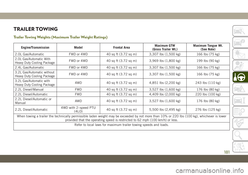
Trailer Towing Weights (Maximum Trailer Weight Ratings)
Engine/Transmission Model Frontal AreaMaximum GTW
(Gross Trailer Wt.)Maximum Tongue Wt.
(See Note)
2.0L Gas/Automatic FWD or 4WD 40 sq ft (3.72 sq m) 3,307 lbs (1,500 kg) 166 lbs (75 kg)
2.0L Gas/Automatic With
Heavy Duty Cooling PackageFWD or 4WD 40 sq ft (3.72 sq m) 3,969 lbs (1,800 kg) 199 lbs (90 kg)
2.4L Gas/Automatic FWD or 4WD 40 sq ft (3.72 sq m) 3,307 lbs (1,500 kg) 166 lbs (75 kg)
3.2L Gas/Automatic without
Heavy Duty Cooling PackageFWD or 4WD 40 sq ft (3.72 sq m) 3,307 lbs (1,500 kg) 166 lbs (75 kg)
3.2L Gas/Automatic with
Heavy Duty Cooling Package4WD 40 sq ft (3.72 sq m) 4,851 lbs (2,200 kg) 243 lbs (110 kg)
2.2L Diesel/Manual FWD 40 sq ft (3.72 sq m) 3,527 lbs (1,600 kg) 176 lbs (80 kg)
2.2L Diesel/Automatic FWD 40 sq ft (3.72 sq m) 4,409 lbs (2,000 kg) 220 lbs (100 kg)
2.2L Diesel/Automatic or
ManualAWD 40 sq ft (3.72 sq m) 3,527 lbs (1,600 kg) 176 lbs (80 kg)
2.2L Diesel/Automatic4WD with 2–speed PTU
(4LO)40 sq ft (3.72 sq m) 5,500 lbs (2,495 kg) 276 lbs (125 kg)
When towing a trailer the technically permissible laden weight may be exceeded by not more than 10% or 220 lbs (100 kg), whichever is lower
provided that the operating speed is restricted to 62 mph (100 km/h) or less.
Refer to local laws for maximum trailer towing speeds and loads.
181
Page 185 of 344
Recreational Towing — Front-Wheel Drive
(FWD) Models
DO NOTflat tow this vehicle.
Recreational towing (for front-wheel drive
models) is allowed ONLY if the front wheels
areOFFthe ground. This may be accom-
plished using a tow dolly or vehicle trailer. If
using a tow dolly, follow this procedure:
1. Properly secure the dolly to the tow ve-
hicle, following the dolly manufacturer's
instructions.
2. Drive the front wheels onto the tow dolly.
3. Apply the parking brake. Place automatic
transmission in PARK, or manual trans-
mission in gear. Turn the engine OFF.
4. Properly secure the front wheels to the
dolly, following the dolly manufacturer's
instructions.
5. Turn the ignition to the ON/RUN mode,
but do not start the engine.6. Press and hold the brake pedal.
7. Release the parking brake.
8. Turn the ignition OFF, remove the key fob,
and release the brake pedal.
CAUTION!
• Towing with the front wheels on the
ground will cause severe transmission
damage. Damage from improper towing
is not covered under the New Vehicle
Limited Warranty.
• Ensure that the Electric Park Brake is
released, and remains released, while
being towed.
Recreational Towing — 4x4 Models
Recreational towing is not allowed.
NOTE:
This vehicle may be towed on a flatbed or
vehicle trailer provided all four wheels are
OFF the ground.
CAUTION!
Towing this vehicle withANYof its wheels
on the ground can cause severe transmis-
sion and/or power transfer unit damage.
Damage from improper towing is not cov-
ered under the New Vehicle Limited War-
ranty.
183
Page 187 of 344
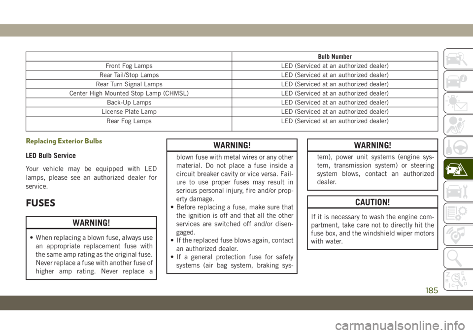
Bulb Number
Front Fog Lamps LED (Serviced at an authorized dealer)
Rear Tail/Stop Lamps LED (Serviced at an authorized dealer)
Rear Turn Signal Lamps LED (Serviced at an authorized dealer)
Center High Mounted Stop Lamp (CHMSL) LED (Serviced at an authorized dealer)
Back-Up Lamps LED (Serviced at an authorized dealer)
License Plate Lamp LED (Serviced at an authorized dealer)
Rear Fog Lamps LED (Serviced at an authorized dealer)
Replacing Exterior Bulbs
LED Bulb Service
Your vehicle may be equipped with LED
lamps, please see an authorized dealer for
service.
FUSES
WARNING!
• When replacing a blown fuse, always use
an appropriate replacement fuse with
the same amp rating as the original fuse.
Never replace a fuse with another fuse of
higher amp rating. Never replace a
WARNING!
blown fuse with metal wires or any other
material. Do not place a fuse inside a
circuit breaker cavity or vice versa. Fail-
ure to use proper fuses may result in
serious personal injury, fire and/or prop-
erty damage.
• Before replacing a fuse, make sure that
the ignition is off and that all the other
services are switched off and/or disen-
gaged.
• If the replaced fuse blows again, contact
an authorized dealer.
• If a general protection fuse for safety
systems (air bag system, braking sys-
WARNING!
tem), power unit systems (engine sys-
tem, transmission system) or steering
system blows, contact an authorized
dealer.
CAUTION!
If it is necessary to wash the engine com-
partment, take care not to directly hit the
fuse box, and the windshield wiper motors
with water.
185
Page 188 of 344
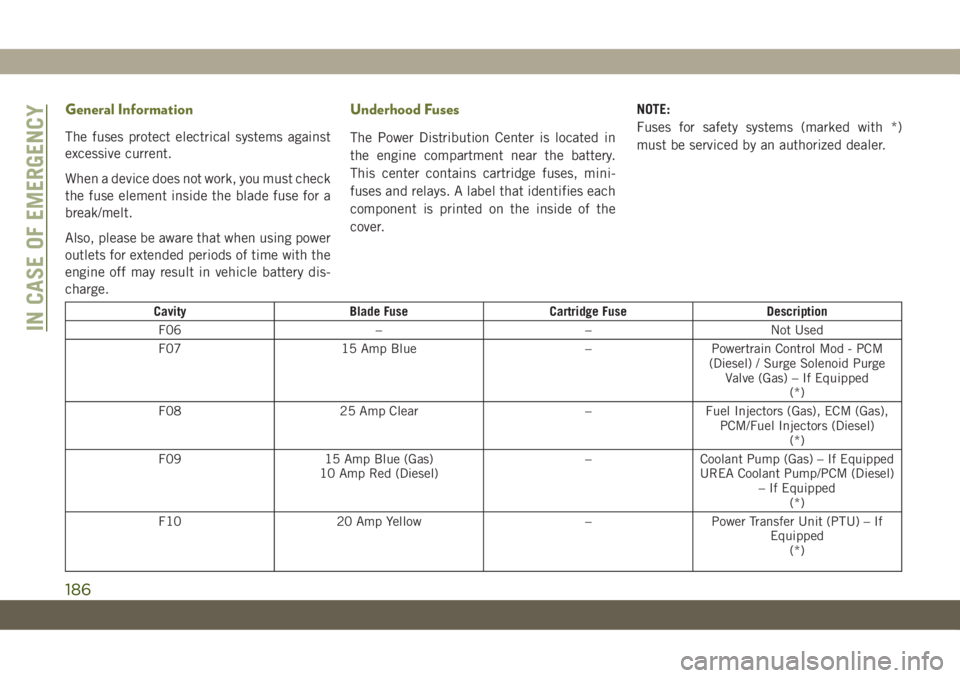
General Information
The fuses protect electrical systems against
excessive current.
When a device does not work, you must check
the fuse element inside the blade fuse for a
break/melt.
Also, please be aware that when using power
outlets for extended periods of time with the
engine off may result in vehicle battery dis-
charge.
Underhood Fuses
The Power Distribution Center is located in
the engine compartment near the battery.
This center contains cartridge fuses, mini-
fuses and relays. A label that identifies each
component is printed on the inside of the
cover.NOTE:
Fuses for safety systems (marked with *)
must be serviced by an authorized dealer.
Cavity Blade Fuse Cartridge Fuse Description
F06 – – Not Used
F07 15 Amp Blue – Powertrain Control Mod - PCM
(Diesel) / Surge Solenoid Purge
Valve (Gas) – If Equipped
(*)
F08 25 Amp Clear – Fuel Injectors (Gas), ECM (Gas),
PCM/Fuel Injectors (Diesel)
(*)
F09 15 Amp Blue (Gas)
10 Amp Red (Diesel)– Coolant Pump (Gas) – If Equipped
UREA Coolant Pump/PCM (Diesel)
– If Equipped
(*)
F10 20 Amp Yellow – Power Transfer Unit (PTU) – If
Equipped
(*)IN CASE OF EMERGENCY
186
Page 189 of 344
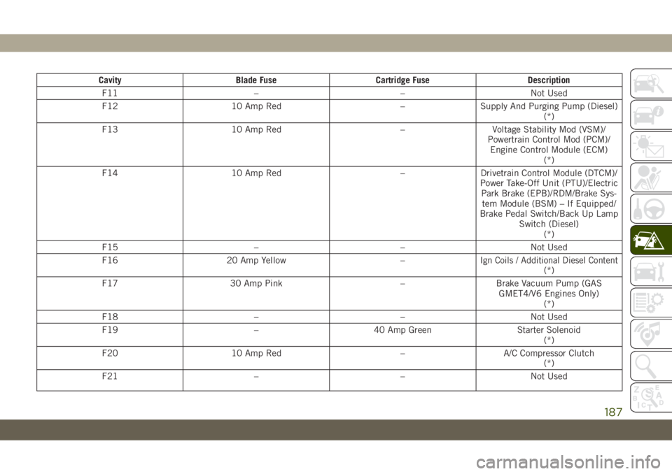
Cavity Blade Fuse Cartridge Fuse Description
F11 – – Not Used
F12 10 Amp Red – Supply And Purging Pump (Diesel)
(*)
F13 10 Amp Red – Voltage Stability Mod (VSM)/
Powertrain Control Mod (PCM)/
Engine Control Module (ECM)
(*)
F14 10 Amp Red – Drivetrain Control Module (DTCM)/
Power Take-Off Unit (PTU)/Electric
Park Brake (EPB)/RDM/Brake Sys-
tem Module (BSM) – If Equipped/
Brake Pedal Switch/Back Up Lamp
Switch (Diesel)
(*)
F15 – – Not Used
F16 20 Amp Yellow – I
gn Coils / Additional Diesel Content(*)
F17 30 Amp Pink – Brake Vacuum Pump (GAS
GMET4/V6 Engines Only)
(*)
F18 – – Not Used
F19 – 40 Amp Green Starter Solenoid
(*)
F20 10 Amp Red – A/C Compressor Clutch
(*)
F21 – – Not Used
187
Page 190 of 344
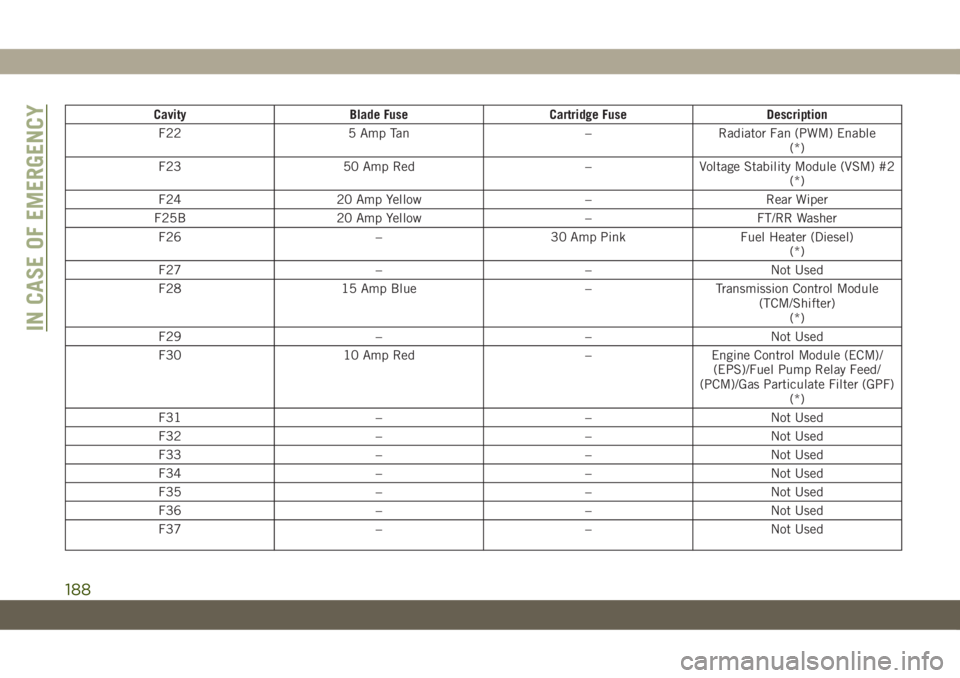
Cavity Blade Fuse Cartridge Fuse Description
F22 5 Amp Tan – Radiator Fan (PWM) Enable
(*)
F23 50 Amp Red – Voltage Stability Module (VSM) #2
(*)
F24 20 Amp Yellow – Rear Wiper
F25B 20 Amp Yellow – FT/RR Washer
F26 – 30 Amp Pink Fuel Heater (Diesel)
(*)
F27 – – Not Used
F28 15 Amp Blue – Transmission Control Module
(TCM/Shifter)
(*)
F29 – – Not Used
F30 10 Amp Red – Engine Control Module (ECM)/
(EPS)/Fuel Pump Relay Feed/
(PCM)/Gas Particulate Filter (GPF)
(*)
F31 – – Not Used
F32 – – Not Used
F33 – – Not Used
F34 – – Not Used
F35 – – Not Used
F36 – – Not Used
F37 – – Not Used
IN CASE OF EMERGENCY
188
Page 193 of 344
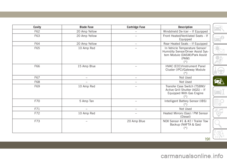
Cavity Blade Fuse Cartridge Fuse Description
F62 20 Amp Yellow – Windshield De-Icer – If Equipped
F63 20 Amp Yellow – Front Heated/Ventilated Seats - If
Equipped
F64 20 Amp Yellow – Rear Heated Seats – If Equipped
F65 10 Amp Red – In Vehicle Temperature Sensor/
Humidity Sensor/Driver Assist Sys-
tem Module (DASM)/Park Assist
(PAM)
(*)
F66 15 Amp Blue – HVAC (ECC)/Instrument Panel
Cluster (IPC)/Gateway Module
(*)
F67 – – Not Used
F68 – – Not Used
F69 10 Amp Red – Transfer Case Switch (TSBM)/
Active Grill Shutter (AGS) – If
Equipped With Gas Engine
(*)
F70 5 Amp Tan – Intelligent Battery Sensor (IBS)
(*)
F71 – – Not Used
F72 10 Amp Red – Heated Mirrors (Gas) / PM Sensor
(Diesel)
F73 – 20 Amp Blue NOX Sensor #1 & #2 / Trailer Tow
Backup (NAFTA & Gas)
(*)
191
Page 194 of 344
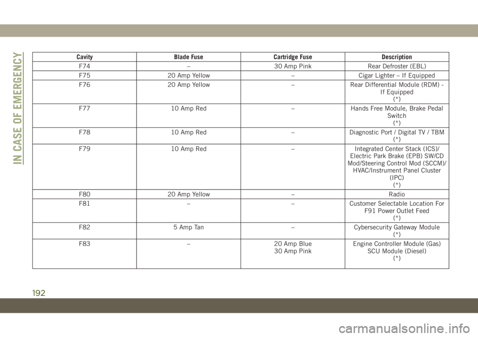
Cavity Blade Fuse Cartridge Fuse Description
F74 – 30 Amp Pink Rear Defroster (EBL)
F75 20 Amp Yellow – Cigar Lighter – If Equipped
F76 20 Amp Yellow – Rear Differential Module (RDM) -
If Equipped
(*)
F77 10 Amp Red – Hands Free Module, Brake Pedal
Switch
(*)
F78 10 Amp Red – Diagnostic Port / Digital TV / TBM
(*)
F79 10 Amp Red – Integrated Center Stack (ICS)/
Electric Park Brake (EPB) SW/CD
Mod/Steering Control Mod (SCCM)/
HVAC/Instrument Panel Cluster
(IPC)
(*)
F80 20 Amp Yellow – Radio
F81 – – Customer Selectable Location For
F91 Power Outlet Feed
(*)
F82 5 Amp Tan – Cybersecurity Gateway Module
(*)
F83 – 20 Amp Blue
30 Amp PinkEngine Controller Module (Gas)
SCU Module (Diesel)
(*)
IN CASE OF EMERGENCY
192