warning JEEP CHEROKEE 2023 Owner's Guide
[x] Cancel search | Manufacturer: JEEP, Model Year: 2023, Model line: CHEROKEE, Model: JEEP CHEROKEE 2023Pages: 276, PDF Size: 12.55 MB
Page 54 of 276
52GETTING TO KNOW YOUR VEHICLE
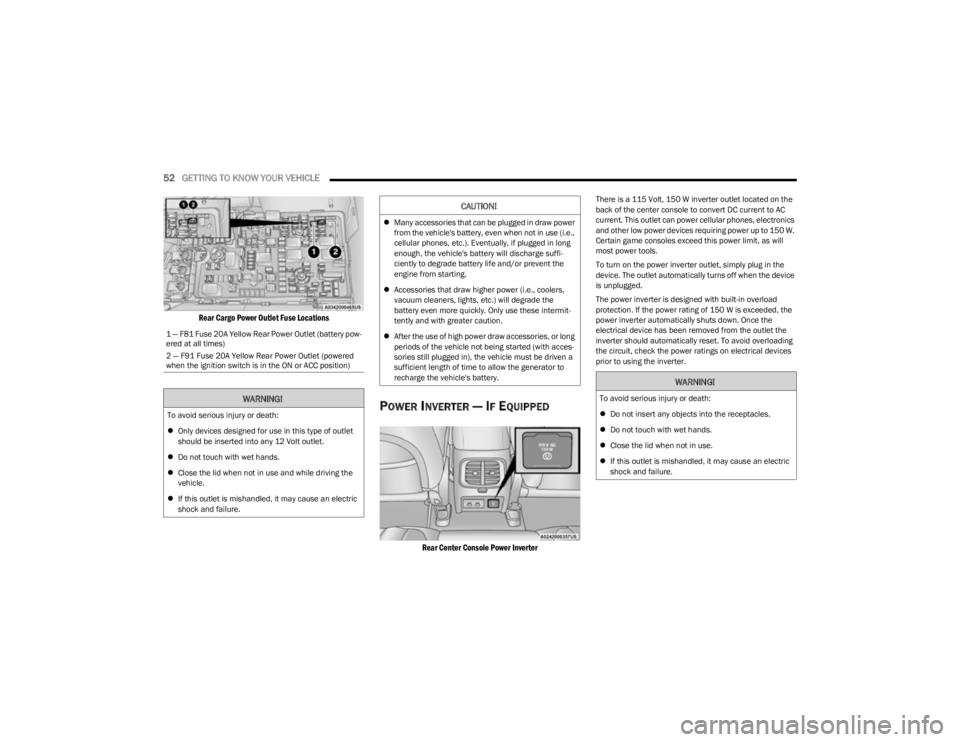
Rear Cargo Power Outlet Fuse Locations
POWER INVERTER — IF EQUIPPED
Rear Center Console Power Inverter
There is a 115 Volt, 150 W inverter outlet located on the
back of the center console to convert DC current to AC
current. This outlet can power cellular phones, electronics
and other low power devices requiring power up to 150 W.
Certain game consoles exceed this power limit, as will
most power tools.
To turn on the power inverter outlet, simply plug in the
device. The outlet automatically turns off when the device
is unplugged.
The power inverter is designed with built-in overload
protection. If the power rating of 150 W is exceeded, the
power inverter automatically shuts down. Once the
electrical device has been removed from the outlet the
inverter should automatically reset. To avoid overloading
the circuit, check the power ratings on electrical devices
prior to using the inverter.
1 — F81 Fuse 20A Yellow Rear Power Outlet (battery pow
-
ered at all times)
2 — F91 Fuse 20A Yellow Rear Power Outlet (powered
when the ignition switch is in the ON or ACC position)
WARNING!
To avoid serious injury or death:
Only devices designed for use in this type of outlet
should be inserted into any 12 Volt outlet.
Do not touch with wet hands.
Close the lid when not in use and while driving the
vehicle.
If this outlet is mishandled, it may cause an electric
shock and failure.
CAUTION!
Many accessories that can be plugged in draw power
from the vehicle's battery, even when not in use (i.e.,
cellular phones, etc.). Eventually, if plugged in long
enough, the vehicle's battery will discharge suffi -
ciently to degrade battery life and/or prevent the
engine from starting.
Accessories that draw higher power (i.e., coolers,
vacuum cleaners, lights, etc.) will degrade the
battery even more quickly. Only use these intermit -
tently and with greater caution.
After the use of high power draw accessories, or long
periods of the vehicle not being started (with acces -
sories still plugged in), the vehicle must be driven a
sufficient length of time to allow the generator to
recharge the vehicle's battery.
WARNING!
To avoid serious injury or death:
Do not insert any objects into the receptacles.
Do not touch with wet hands.
Close the lid when not in use.
If this outlet is mishandled, it may cause an electric
shock and failure.
23_KL_OM_EN_USC_t.book Page 52
Page 55 of 276
GETTING TO KNOW YOUR VEHICLE53
WINDOWS
POWER WINDOW CONTROLS
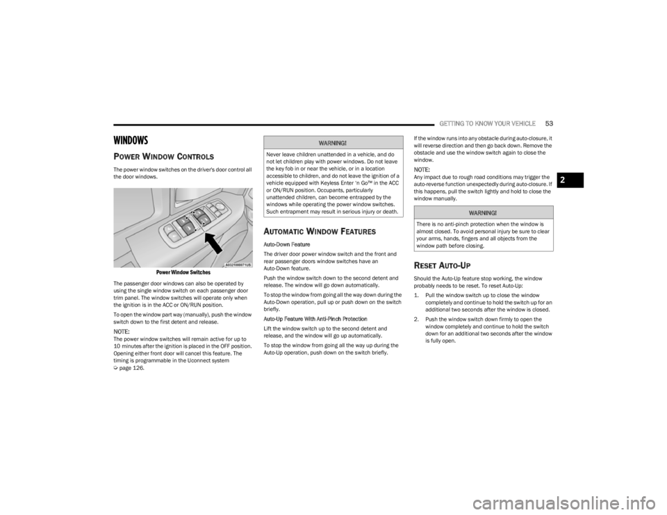
The power window switches on the driver's door control all
the door windows.
Power Window Switches
The passenger door windows can also be operated by
using the single window switch on each passenger door
trim panel. The window switches will operate only when
the ignition is in the ACC or ON/RUN position.
To open the window part way (manually), push the window
switch down to the first detent and release.
NOTE:The power window switches will remain active for up to
10 minutes after the ignition is placed in the OFF position.
Opening either front door will cancel this feature. The
timing is programmable in the Uconnect system
Úpage 126.
AUTOMATIC WINDOW FEATURES
Auto-Down Feature
The driver door power window switch and the front and
rear passenger doors window switches have an
Auto-Down feature.
Push the window switch down to the second detent and
release. The window will go down automatically.
To stop the window from going all the way down during the
Auto-Down operation, pull up or push down on the switch
briefly.
Auto-Up Feature With Anti-Pinch Protection
Lift the window switch up to the second detent and
release, and the window will go up automatically.
To stop the window from going all the way up during the
Auto-Up operation, push down on the switch briefly. If the window runs into any obstacle during auto-closure, it
will reverse direction and then go back down. Remove the
obstacle and use the window switch again to close the
window.
NOTE:Any impact due to rough road conditions may trigger the
auto-reverse function unexpectedly during auto-closure. If
this happens, pull the switch lightly and hold to close the
window manually.
RESET AUTO-UP
Should the Auto-Up feature stop working, the window
probably needs to be reset. To reset Auto-Up:
1. Pull the window switch up to close the window
completely and continue to hold the switch up for an
additional two seconds after the window is closed.
2. Push the window switch down firmly to open the window completely and continue to hold the switch
down for an additional two seconds after the window
is fully open.
WARNING!
Never leave children unattended in a vehicle, and do
not let children play with power windows. Do not leave
the key fob in or near the vehicle, or in a location
accessible to children, and do not leave the ignition of a
vehicle equipped with Keyless Enter ‘n Go™ in the ACC
or ON/RUN position. Occupants, particularly
unattended children, can become entrapped by the
windows while operating the power window switches.
Such entrapment may result in serious injury or death.
WARNING!
There is no anti-pinch protection when the window is
almost closed. To avoid personal injury be sure to clear
your arms, hands, fingers and all objects from the
window path before closing.
2
23_KL_OM_EN_USC_t.book Page 53
Page 56 of 276
54GETTING TO KNOW YOUR VEHICLE
(Continued)
WINDOW LOCKOUT SWITCH
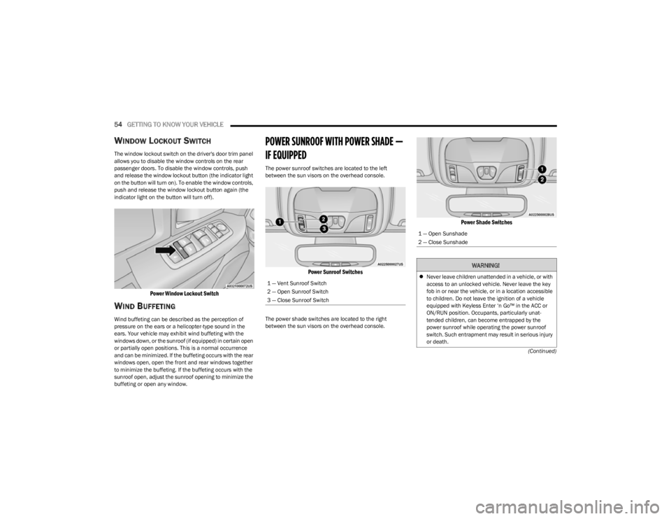
The window lockout switch on the driver's door trim panel
allows you to disable the window controls on the rear
passenger doors. To disable the window controls, push
and release the window lockout button (the indicator light
on the button will turn on). To enable the window controls,
push and release the window lockout button again (the
indicator light on the button will turn off).
Power Window Lockout Switch
WIND BUFFETING
Wind buffeting can be described as the perception of
pressure on the ears or a helicopter-type sound in the
ears. Your vehicle may exhibit wind buffeting with the
windows down, or the sunroof (if equipped) in certain open
or partially open positions. This is a normal occurrence
and can be minimized. If the buffeting occurs with the rear
windows open, open the front and rear windows together
to minimize the buffeting. If the buffeting occurs with the
sunroof open, adjust the sunroof opening to minimize the
buffeting or open any window.
POWER SUNROOF WITH POWER SHADE —
IF EQUIPPED
The power sunroof switches are located to the left
between the sun visors on the overhead console.
Power Sunroof Switches
The power shade switches are located to the right
between the sun visors on the overhead console.
Power Shade Switches
1 — Vent Sunroof Switch
2 — Open Sunroof Switch
3 — Close Sunroof Switch
1 — Open Sunshade
2 — Close Sunshade
WARNING!
Never leave children unattended in a vehicle, or with
access to an unlocked vehicle. Never leave the key
fob in or near the vehicle, or in a location accessible
to children. Do not leave the ignition of a vehicle
equipped with Keyless Enter ‘n Go™ in the ACC or
ON/RUN position. Occupants, particularly unat -
tended children, can become entrapped by the
power sunroof while operating the power sunroof
switch. Such entrapment may result in serious injury
or death.
23_KL_OM_EN_USC_t.book Page 54
Page 57 of 276
GETTING TO KNOW YOUR VEHICLE55
OPENING AND CLOSING THE SUNROOF
The sunroof has two programmed open positions: comfort
stop position and full open position. The comfort stop
position is set to minimize wind buffeting when driving
with side windows closed and sunroof open. If the
sunshade is closed when initiating a sunroof open or vent
command, the sunshade will automatically open to the
half open position prior to the sunroof opening.
Express Open/Close
Push the switch rearward to open and release it within one
second, the sunroof will open to the comfort stop position
and automatically stop. Push the switch rearward and
release it again, the sunroof will open to the full open
position and automatically stop. This is called Express
Open.
Push the switch forward to close and release it within one
second and the sunroof will close automatically from any
position. The sunroof will close fully and stop
automatically. This is called Express Close. During Express Open or Express Close operation, any
movement of the sunshade switch will stop the shade.
Manual Open/Close
Push and hold the switch rearward to open. The sunroof
will open to the comfort stop position and automatically
stop. Push the switch rearward and hold it again, the
sunroof will open to the full open position and
automatically stop.
To close the sunroof, push and hold the switch in the
forward position.
Any release of the switch during open or close operation
will stop the sunroof movement. The sunroof will remain in
a partially opened position until the switch is operated and
held again.OPENING AND CLOSING THE POWER
S
HADE
The sunshade has two programmed open positions: half
open and full open. When opening the sunshade from the
closed position the sunshade will always stop at the half
open position regardless of express or manual open
operation. The switch must be actuated again to continue
on to full open position.
If the sunroof is open or vented the sunshade cannot be
closed beyond the half open position. Pushing the
sunshade close switch when the sunroof is open/vented
and the sunshade is at half open position will first
automatically close sunroof prior to the sunshade closing. Express Open/Close
Push the sunshade switch rearward to open and release it
within one second, the sunshade will open to the half open
position and stop automatically. Push and release the
switch again from the half open position and the
sunshade will open to the full open position and stop
automatically. This is called Express Open.
Push the sunshade switch forward to close and release it
within one second. If the sunroof is in closed position the
sunshade will full close automatically from any position. If
the sunroof is open or vented the sunshade will close to
the half open position and stop; push and release the
sunshade switch forward again to automatically close
both the sunroof and sunshade completely. This is called
Express Close.
During Express Open or Express Close operation, any
movement of the sunshade switch will stop the shade.
Manual Open/Close
Push and hold the sunshade switch rearward to open. The
shade will open to the half open position and stop
automatically. Push and hold the sunshade switch
rearward again and the shade will open automatically to
the full open position.
Push and hold the sunshade switch forward to close. If the
sunroof is in closed position the sunshade will full close
from any position. If the sunroof is open or vented the
sunshade will close to the half open position and stop;
pushing and holding the sunshade switch forward again
will close both the sunroof and sunshade completely.
Any release of the switch will stop the movement and the
sunshade will remain in a partially opened position until
the switch is pushed again.
In a collision, there is a greater risk of being thrown
from a vehicle with an open sunroof. You could also
be seriously injured or killed. Always fasten your seat
belt properly and make sure all passengers are also
properly secured.
Do not allow small children to operate the sunroof.
Never allow your fingers, other body parts, or any
object, to project through the sunroof opening. Injury
may result.
WARNING!
2
23_KL_OM_EN_USC_t.book Page 55
Page 59 of 276
GETTING TO KNOW YOUR VEHICLE57
CLOSING THE HOOD
In one continuous motion, pull down on the front edge of
the hood with moderate force until the angle is below the
point where the gas props are no longer resisting. Then let
the hood continue to fall into the closed position on its
own.
LIFTGATE
TO UNLOCK/OPEN THE LIFTGATE
The power liftgate may be opened by pushing the key fob
liftgate button (if equipped) or by pushing the electronic
liftgate release handle
Úpage 22.
Push the liftgate button on the key fob twice within five
seconds to open the power liftgate. Once the liftgate is
open, pushing the button twice within five seconds a
second time will close the liftgate.
The power liftgate may also be opened or closed by
pushing the liftgate button located on the instrument
panel to right of the headlight switch. If the liftgate is fully
open, the liftgate can be closed by pushing the liftgate
button located on the left rear trim panel, near the liftgate opening. If the liftgate is in motion, pushing the liftgate
button located on the left rear trim panel will reverse the
liftgate.
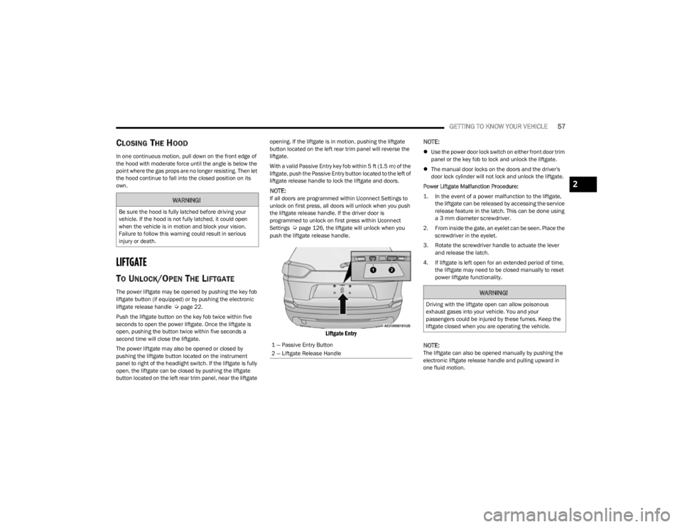
With a valid Passive Entry key fob within 5 ft (1.5 m) of the
liftgate, push the Passive Entry button located to the left of
liftgate release handle to lock the liftgate and doors.
NOTE:If all doors are programmed within Uconnect Settings to
unlock on first press, all doors will unlock when you push
the liftgate release handle. If the driver door is
programmed to unlock on first press within Uconnect
Settings
Úpage 126, the liftgate will unlock when you
push the liftgate release handle.
Liftgate Entry
NOTE:
Use the power door lock switch on either front door trim
panel or the key fob to lock and unlock the liftgate.
The manual door locks on the doors and the driver's
door lock cylinder will not lock and unlock the liftgate.
Power Liftgate Malfunction Procedure:
1. In the event of a power malfunction to the liftgate, the liftgate can be released by accessing the service
release feature in the latch. This can be done using
a 3 mm diameter screwdriver.
2. From inside the gate, an eyelet can be seen. Place the screwdriver in the eyelet.
3. Rotate the screwdriver handle to actuate the lever and release the latch.
4. If liftgate is left open for an extended period of time, the liftgate may need to be closed manually to reset
power liftgate functionality.
NOTE:The liftgate can also be opened manually by pushing the
electronic liftgate release handle and pulling upward in
one fluid motion.
WARNING!
Be sure the hood is fully latched before driving your
vehicle. If the hood is not fully latched, it could open
when the vehicle is in motion and block your vision.
Failure to follow this warning could result in serious
injury or death.
1 — Passive Entry Button
2 — Liftgate Release Handle
WARNING!
Driving with the liftgate open can allow poisonous
exhaust gases into your vehicle. You and your
passengers could be injured by these fumes. Keep the
liftgate closed when you are operating the vehicle.
2
23_KL_OM_EN_USC_t.book Page 57
Page 61 of 276
GETTING TO KNOW YOUR VEHICLE59
There are pinch sensors attached to the side of the lift -
gate opening. Light pressure anywhere along these
strips will cause the liftgate to return to the open posi -
tion.
If the power liftgate encounters multiple obstructions
within the same cycle, the system will automatically
stop. If this occurs, the liftgate must be operated manu -
ally.
The power liftgate will release, but not power open, in
temperatures below −12°F (−24°C). Be sure to
remove any buildup of snow or ice from the liftgate
before opening the liftgate.
If the liftgate is left open for an extended period of time,
the liftgate may need to be closed manually to reset
power liftgate functionality.
Gas props support the liftgate in the open position.
However, because the gas pressure drops with
temperature, it may be necessary to assist the props when
opening the liftgate in cold weather.NOTE:Allow the power system to open the liftgate. Manually
pushing or pulling the liftgate may activate the liftgate
obstacle detection feature and stop the power operation
or reverse its direction.
CARGO AREA FEATURES
Cargo Load Floor
The cargo load floor system has a load capacity of 300 lb
(136 kg).
To provide additional storage area, each rear seat can be
folded flat. This allows for extended cargo space and still
maintains some rear seating room
Úpage 28.
Cargo Tie-Down Hooks And Loops
The tie-downs located on the cargo area floor should be
used to secure loads safely when the vehicle is moving.
Cargo tie-down loops are located on the trim panels.
WARNING!
Driving with the liftgate open can allow poisonous
exhaust gases into your vehicle. You and your
passengers could be injured by these fumes. Keep
the liftgate closed when you are operating the
vehicle.
If you are required to drive with the liftgate open,
make sure that all windows are closed, and the
climate control blower switch is set at high speed. Do
not use the recirculation mode.
WARNING!
During power operation, personal injury or cargo
damage may occur. Ensure the liftgate travel path is
clear. Make sure the liftgate is closed and latched
before driving away.
WARNING!
Cargo tie-downs are not safe anchors for a child seat
tether strap. In a sudden stop or accident, a tie-down
could pull loose and allow the child seat to come
loose. A child could be badly injured. Use only the
anchors provided for child seat tethers.
To help protect against personal injury, passengers
should not be seated in the rear cargo area. The rear
cargo space is intended for load carrying purposes
only, not for passengers, who should sit in seats and
use seat belts.
The weight and position of cargo and passengers can
change the vehicle center of gravity and vehicle
handling. To avoid loss of control resulting in personal
injury, follow these guidelines for loading your vehicle:
Do not carry loads that exceed the load limits
described on the label attached to the left door or left
door center pillar.
Always place cargo evenly on the cargo floor. Put
heavier objects as low and as far forward as possible.
Place as much cargo as possible in front of the rear
axle. Too much weight or improperly placed weight
over or behind the rear axle can cause the vehicle to
sway.
Do not pile luggage or cargo higher than the top of
the seatback. This could impair visibility or become a
dangerous projectile in a sudden stop or accident.
2
23_KL_OM_EN_USC_t.book Page 59
Page 62 of 276
60GETTING TO KNOW YOUR VEHICLE
(Continued)
Rear Storage Bins
The rear storage bins are located in the rear of the vehicle
on the sides of the load floor.
ROOF LUGGAGE RACK — IF EQUIPPED
The load carried on the roof, when equipped with a
luggage rack, must not exceed 150 lb (68 kg), and it
should be uniformly distributed over the cargo area.
Crossbars should always be used whenever cargo is
placed on the roof rack. Check the straps frequently to be
sure that the load remains securely attached.
NOTE:Crossbars can be purchased at an authorized dealer
through Mopar® parts.
External racks do not increase the total load carrying
capacity of the vehicle. Be sure that the total occupant
and luggage load inside the vehicle, plus the load on the
luggage rack, does not exceed the maximum vehicle load
capacity.
WARNING!
Cargo must be securely tied down before driving your
vehicle. Improperly secured loads can fly off the vehicle,
particularly at high speeds, resulting in personal injury
or property damage. Follow the roof rack cautions when
carrying cargo on your roof rack.
CAUTION!
To avoid damage to the roof rack and vehicle, do not
exceed the maximum roof rack load capacity. Always
distribute heavy loads as evenly as possible and
secure the load appropriately.
Long loads, which extend over the windshield, should
be secured to both the front and rear of the vehicle.
Place a blanket or other protection between the
surface of the roof and the load.
Travel at reduced speeds and turn corners carefully
when carrying large or heavy loads on the roof rack.
Wind forces, due to natural causes or nearby truck
traffic, can add sudden upward lift to a load. It is
recommended to not carry large flat loads, such as
wood panels or surfboards, which may result in
damage to the cargo or your vehicle.
Loads should always be secured to crossbars first,
with tie down loops used as additional securing
points if needed. Tie loops are intended as supple -
mentary tie down points only. Do not use ratcheting
mechanisms with the tie loops. Check the straps
frequently to be sure that the load remains securely
attached.
CAUTION!
23_KL_OM_EN_USC_t.book Page 60
Page 65 of 276
GETTING TO KNOW YOUR INSTRUMENT PANEL63
INSTRUMENT CLUSTER DESCRIPTIONS
Use this QR code to access your digital
experience.
1. Tachometer
Indicates the engine speed in
revolutions per minute (RPM x
1000).
2. Instrument Cluster Display The instrument cluster display features a driver
interactive display
Úpage 63.
3. Speedometer Indicates vehicle speed.
4. Temperature Gauge The temperature gauge shows engine coolant
temperature. Any reading within the normal range
indicates that the engine cooling system is oper -
ating satisfactorily.
The gauge will likely indicate a higher temperature
when driving in hot weather or up mountain
grades. It should not be allowed to exceed the
upper limits of the normal operating range. 5. Fuel Gauge
The fuel gauge shows the level of fuel in the fuel
tank when the ignition is in the ON/RUN mode.
The fuel pump symbol points to the side
of the vehicle where the fuel door is
located
Úpage 113.
NOTE:The hard telltales will illuminate for a bulb check when the
ignition is first cycled.
INSTRUMENT CLUSTER DISPLAY
Your vehicle may be equipped with an instrument cluster
display, which offers useful information to the driver. With
the ignition in the OFF mode, opening/closing of a door will
activate the display for viewing, and display the total miles
or kilometers in the odometer. The steering wheel
mounted controls allow you to scroll through and enter the
main menus and submenus.
INSTRUMENT CLUSTER DISPLAY
L
OCATION AND CONTROLS
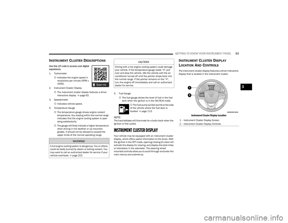
The instrument cluster display features a driver interactive
display that is located in the instrument cluster.
Instrument Cluster Display Location
WARNING!
A hot engine cooling system is dangerous. You or others
could be badly burned by steam or boiling coolant. You
may want to call an authorized dealer for service if your
vehicle overheats
Úpage 222.
CAUTION!
Driving with a hot engine cooling system could damage
your vehicle. If the temperature gauge reads “H” pull
over and stop the vehicle. Idle the vehicle with the air
conditioner turned off until the pointer drops back into
the normal range. If the pointer remains on the “H”,
turn the engine off immediately and call an authorized
dealer for service.
1 – Instrument Cluster Display Screen
2 – Instrument Cluster Display Controls
3
23_KL_OM_EN_USC_t.book Page 63
Page 67 of 276
GETTING TO KNOW YOUR INSTRUMENT PANEL65
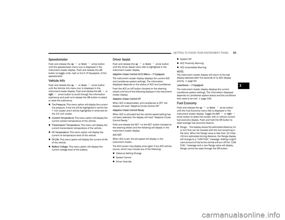
Speedometer
Push and release the up or down arrow button
until the speedometer menu icon is displayed in the
instrument cluster display. Push and release the OK
button to toggle units, mph or km/h (If Equipped), of the
speedometer.
Vehicle Info
Push and release the up or down arrow button
until the Vehicle Info menu icon is displayed in the
instrument cluster display. Push and release the left or
right arrow button to scroll through the information
submenus and push and release the OK button to select
or reset the submenus.
Tire Pressure : This menu option will display the current
tire pressure. A low tire will be highlighted in red for the
7 inch cluster and it will be highlighted in white text for
the 3.5 inch cluster.
Coolant Temperature : This menu option will display the
current coolant temperature of the vehicle.
Transmission Temperature : This menu will display the
current transmission temperature of the vehicle.
Oil Temperature : This menu option will display the
current oil temperature level of the vehicle.
Oil Life: This menu option will display the current oil life
of the vehicle.
Battery Voltage : This menu option will display the
current voltage level of the battery.
Driver Assist
Push and release the up or down arrow button
until the Driver Assist menu title is highlighted in the
instrument cluster display.
Adaptive Cruise Control (ACC) Menu — If Equipped
The instrument cluster display displays the current ACC
and LaneSense system settings. The information
displayed depends on the status of ACC and LaneSense.
Push the ACC on/off button (located on the steering
wheel) until one of the following displays in the instrument
cluster display:
Adaptive Cruise Control Off
When ACC is deactivated, and LaneSense is OFF, the
display will read “Adaptive Cruise Control Off.”
Adaptive Cruise Control Ready
When ACC is activated but the vehicle speed setting has
not been selected, the display will read “Adaptive Cruise
Control Ready.”
Push and release the SET + or the SET- button (located on
the steering wheel) and the following will display in the
instrument cluster display:
ACC SET
When ACC is set, the set speed will display in the
instrument cluster.
The ACC screen may display once again if any ACC activity
occurs, which may include any of the following:
Distance Setting Change
System Cancel
Driver Override
System Off
ACC Proximity Warning
ACC Unavailable Warning
NOTE:The instrument cluster display will return to the last
display selected after five seconds of no ACC display
activity
Úpage 92.
LaneSense — If Equipped
The instrument cluster display displays the current
LaneSense system settings. The information displayed
depends on LaneSense system status and the conditions
that need to be met
Úpage 109.
Fuel Economy
Push and release the up or down arrow button
until the Fuel Economy menu title is displayed in the
instrument cluster display. Toggle the left or right
arrow button to select the screen with or without current
fuel economy display. Push and hold the OK button to
reset average fuel economy feature.
Range – The display shows the estimated distance (mi
or km) that can be traveled with the fuel remaining in
the tank. When the Range value is less than 10 miles
(16 km) estimated driving distance, the Range display
will change to a “LOW FUEL” message. Adding a signif -
icant amount of fuel to the vehicle will turn off the “LOW
FUEL” message and a new Range value will display.
Range cannot be reset through the OK button.
3
23_KL_OM_EN_USC_t.book Page 65
Page 68 of 276
66GETTING TO KNOW YOUR INSTRUMENT PANEL
NOTE:Significant changes in driving style or vehicle loading will
greatly affect the actual drivable distance of the vehicle,
regardless of the Range displayed value.
Average – The display shows the average fuel economy
(MPG, L/100 km, or km/L) since the last reset.
Current – This display shows the current fuel economy
(MPG, L/100 km, or km/L) form while driving.
Trip Info
Push and release the up or down arrow button
until the Trip menu title is displayed in the instrument
cluster display. Toggle the left or right arrow button
to select Trip A or Trip B. The Trip information will display
the following:
Distance – Shows the total distance (mi or km) traveled
for Trip A or Trip B since the last reset.
Average Fuel Economy – Shows the average fuel
economy (MPG or L/100 km or km/L) of Trip A or Trip
B since the last reset.
Elapsed Time – Shows the total elapsed time of travel
since Trip A or Trip B has been reset.
Hold the OK button to reset feature information.
Stop/Start – If Equipped
Push and release the up or down arrow button
until the Stop/Start menu title is displayed in the
instrument cluster display.
Audio
Push and release the up or down arrow button
until the Audio menu title is displayed in the instrument
cluster display.
Messages
Push and release the up or down arrow button
until the Messages Menu Icon is highlighted in the
instrument cluster display. This feature shows the number
of stored warning messages. Pushing the left or
right arrow button will allow you to scroll through the
stored messages.
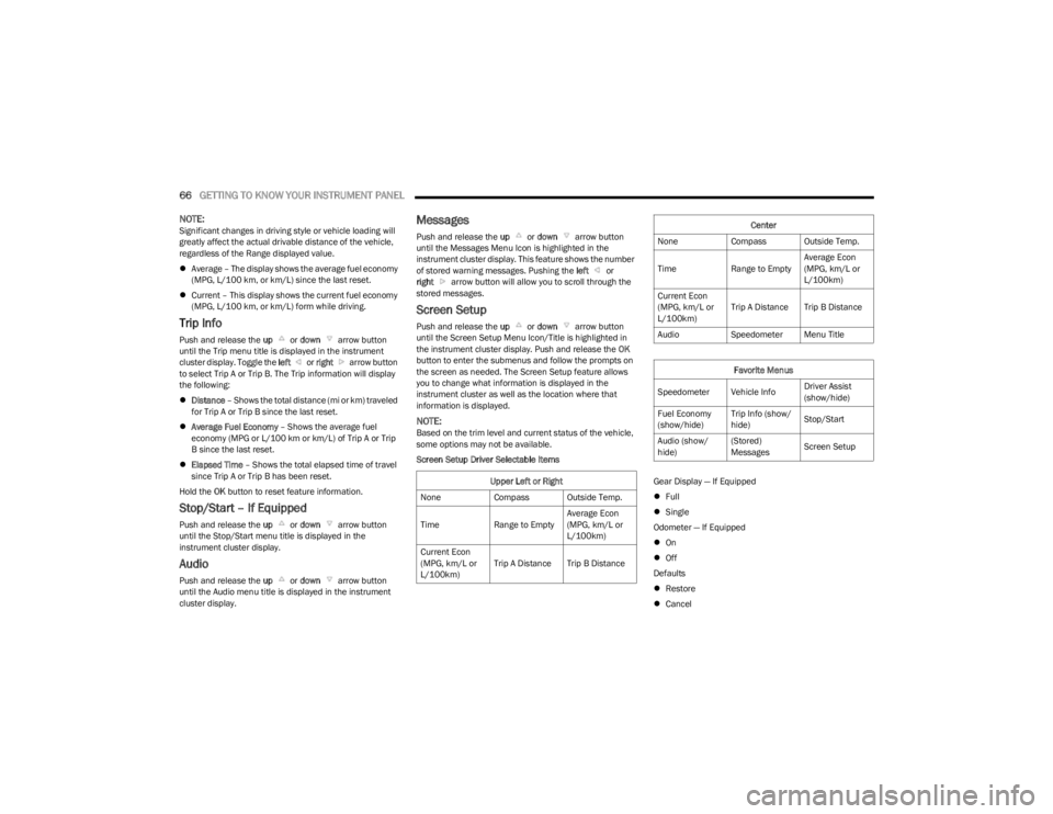
Screen Setup
Push and release the up or down arrow button
until the Screen Setup Menu Icon/Title is highlighted in
the instrument cluster display. Push and release the OK
button to enter the submenus and follow the prompts on
the screen as needed. The Screen Setup feature allows
you to change what information is displayed in the
instrument cluster as well as the location where that
information is displayed.
NOTE:Based on the trim level and current status of the vehicle,
some options may not be available.
Screen Setup Driver Selectable Items
Gear Display — If Equipped
Full
Single
Odometer — If Equipped
On
Off
Defaults
Restore
Cancel
Upper Left or Right
None Compass Outside Temp.
Time Range to EmptyAverage Econ
(MPG, km/L or
L/100km)
Current Econ
(MPG, km/L or
L/100km) Trip A Distance Trip B Distance
Center
None Compass Outside Temp.
Time Range to EmptyAverage Econ
(MPG, km/L or
L/100km)
Current Econ
(MPG, km/L or
L/100km) Trip A Distance Trip B Distance
Audio Speedometer Menu Title
Favorite Menus
Speedometer Vehicle Info Driver Assist
(show/hide)
Fuel Economy
(show/hide) Trip Info (show/
hide)
Stop/Start
Audio (show/
hide) (Stored)
Messages
Screen Setup
23_KL_OM_EN_USC_t.book Page 66