USB port JEEP CHEROKEE 2023 Owners Manual
[x] Cancel search | Manufacturer: JEEP, Model Year: 2023, Model line: CHEROKEE, Model: JEEP CHEROKEE 2023Pages: 276, PDF Size: 12.55 MB
Page 52 of 276
50GETTING TO KNOW YOUR VEHICLE
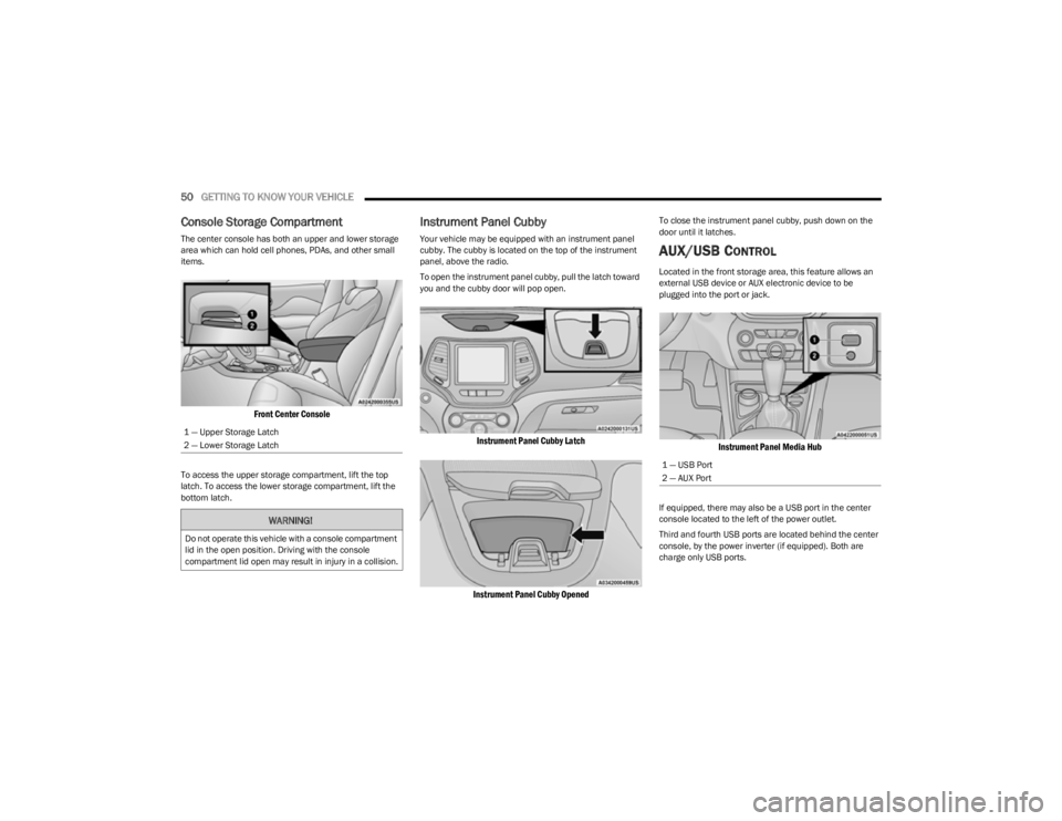
Console Storage Compartment
The center console has both an upper and lower storage
area which can hold cell phones, PDAs, and other small
items.
Front Center Console
To access the upper storage compartment, lift the top
latch. To access the lower storage compartment, lift the
bottom latch.
Instrument Panel Cubby
Your vehicle may be equipped with an instrument panel
cubby. The cubby is located on the top of the instrument
panel, above the radio.
To open the instrument panel cubby, pull the latch toward
you and the cubby door will pop open.
Instrument Panel Cubby Latch
Instrument Panel Cubby Opened
To close the instrument panel cubby, push down on the
door until it latches.
AUX/USB CONTROL
Located in the front storage area, this feature allows an
external USB device or AUX electronic device to be
plugged into the port or jack.
Instrument Panel Media Hub
If equipped, there may also be a USB port in the center
console located to the left of the power outlet.
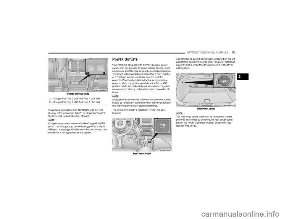
Third and fourth USB ports are located behind the center
console, by the power inverter (if equipped). Both are
charge only USB ports.
1 — Upper Storage Latch
2 — Lower Storage LatchWARNING!
Do not operate this vehicle with a console compartment
lid in the open position. Driving with the console
compartment lid open may result in injury in a collision.
1 — USB Port
2 — AUX Port
23_KL_OM_EN_USC_t.book Page 50
Page 53 of 276
GETTING TO KNOW YOUR VEHICLE51
Charge Only USB Ports
If equipped with a Uconnect 4C/4C NAV with 8.4-inch
Display, refer to “Android Auto™” or “Apple CarPlay®” in
the Uconnect Radio Instruction Manual.
NOTE:Charge unsupported devices with the Charge Only USB
ports. If an unsupported device is plugged into a Media
USB port, a message will display on the touchscreen that
the device is not supported by the system.
POWER OUTLETS
Your vehicle is equipped with 12 Volt (13 Amp) power
outlets that can be used to power cellular phones, small
electronics, and other low powered electrical accessories.
The power outlets are labeled with either a “key” symbol
or a “battery” symbol to indicate how the outlet is
powered. Power outlets labeled with a key symbol are
powered when the ignition switch is in the ON or ACC
position, while the outlets labeled with a battery symbol
are connected directly to the battery and powered at all
times.
NOTE:All accessories connected to the battery powered outlets
should be removed or turned off when the vehicle is not in
use to protect the battery against discharge.
The front power outlet is located in front of the gear
selector.
Front Power Outlet
A second fused 12 Volt power outlet is located on the left
quarter trim panel in the cargo area. This power outlet has
power available when the ignition switch is in the ON or
ACC position.
Rear Power Outlet
NOTE:
The rear cargo power outlet can be changed to battery
powered at all times by switching the rear power outlet
fuse in the Power Distribution Center panel from fuse
location F91 to F81.
1 — Charge Only Type C USB And Type A USB Port
2 — Charge Only Type C USB And Type A USB Port
2
23_KL_OM_EN_USC_t.book Page 51
Page 69 of 276
GETTING TO KNOW YOUR INSTRUMENT PANEL67
INSTRUMENT CLUSTER DISPLAY
S
ELECTABLE ITEMS
The instrument cluster display can be used to view the
following main menu items:
NOTE:Depending on the vehicles options, feature settings may
vary Úpage 63.
BATTERY SAVER ON/BATTERY SAVER
M
ODE MESSAGE — ELECTRICAL LOAD
R
EDUCTION ACTIONS — IF EQUIPPED
This vehicle is equipped with an Intelligent Battery Sensor
(IBS) to perform additional monitoring of the electrical
system and status of the vehicle battery.
In cases when the IBS detects charging system failure, or
the vehicle battery conditions are deteriorating, electrical
load reduction actions will take place to extend the driving
time and distance of the vehicle. This is done by reducing
power to or turning off non-essential electrical loads.
Load reduction is only active when the engine is running.
It will display a message if there is a risk of battery
depletion to the point where the vehicle may stall due to
lack of electrical supply, or will not restart after the current
drive cycle. When load reduction is activated, the message “Battery
Saver On” or “Battery Saver Mode” will appear in the
instrument cluster display.
These messages indicate the vehicle battery has a low
state of charge and continues to lose electrical charge at
a rate that the charging system cannot sustain.
NOTE:
The charging system is independent from load reduc -
tion. The charging system performs a diagnostic on the
charging system continuously.
If the Battery Charge Warning Light is on it may indicate
a problem with the charging system
Úpage 69.
The electrical loads that may be switched off (if equipped),
and vehicle functions which can be effected by load
reduction:
Heated Seats / Vented Seats / Heated Wheel
Heated / Cooled Cup Holders — If Equipped
Rear Defroster And Heated Mirrors
HVAC System
150W Power Inverter System
Audio and Telematics System
Loss of the battery charge may indicate one or more of the
following conditions:
The charging system cannot deliver enough electrical
power to the vehicle system because the electrical
loads are larger than the capability of charging system.
The charging system is still functioning properly.
Turning on all possible vehicle electrical loads
(e.g. HVAC to max settings, exterior and interior
lights, overloaded power outlets +12 Volts, 150W,
USB ports) during certain driving conditions
(city driving, towing, frequent stopping).
Installing options like additional lights, upfitter elec -
trical accessories, audio systems, alarms and similar
devices.
Unusual driving cycles (short trips separated by long
parking periods).
The vehicle was parked for an extended period of time
(weeks, months).
The battery was recently replaced and was not charged
completely.
The battery was discharged by an electrical load left on
when the vehicle was parked.
The battery was used for an extended period with the
engine not running to supply radio, lights, chargers,
+12 Volts portable appliances like vacuum cleaner’s,
game consoles and similar devices.
What to do when an electrical load reduction action
message is present (“Battery Saver On” or “Battery
Saver Mode”)
During a trip:
Reduce power to unnecessary loads if possible:
Turn off redundant lights (interior or exterior).
Check what may be plugged in to power outlets
+12 Volts, 150W, USB ports.
Check HVAC settings (blower, temperature).
Check the audio settings (volume).
Speedometer Vehicle Info Stop/Start
Audio
Driver Assist Fuel Economy
Messages Screen Setup Trip
3
23_KL_OM_EN_USC_t.book Page 67
Page 232 of 276
230SERVICING AND MAINTENANCE
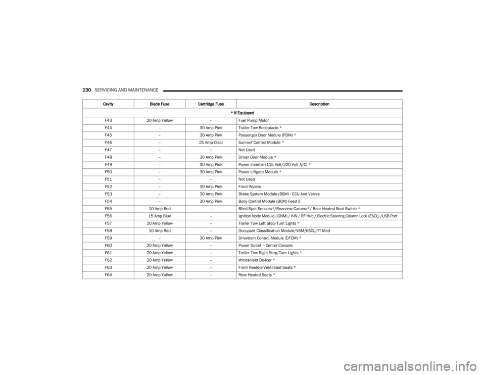
F4320 Amp Yellow –Fuel Pump Motor
F44 –30 Amp Pink Trailer Tow Receptacle *
F45 –30 Amp Pink Passenger Door Module (PDM) *
F46 –25 Amp Clear Sunroof Control Module *
F47 ––Not Used
F48 –30 Amp Pink Driver Door Module *
F49 –30 Amp Pink Power Inverter (115 Volt/220 Volt A/C) *
F50 –30 Amp Pink Power Liftgate Module *
F51 ––Not Used
F52 –30 Amp Pink Front Wipers
F53 –30 Amp Pink Brake System Module (BSM) - ECU And Valves
F54 –30 Amp Pink Body Control Module (BCM) Feed 3
F55 10 Amp Red –Blind Spot Sensors*/Rearview Camera*/ Rear Heated Seat Switch *
F56 15 Amp Blue –Ignition Node Module (IGNM) / KIN / RF Hub / Electric Steering Column Lock (ESCL) /USB Port
F57 20 Amp Yellow –Trailer Tow Left Stop/Turn Lights *
F58 10 Amp Red –Occupant Classification Module/VSM/ESCL/TT Mod
F59 –30 Amp Pink Drivetrain Control Module (DTCM) *
F60 20 Amp Yellow –Power Outlet – Center Console
F61 20 Amp Yellow –Trailer Tow Right Stop/Turn Lights *
F62 20 Amp Yellow –Windshield De-Icer *
F63 20 Amp Yellow –Front Heated/Ventilated Seats *
F64 20 Amp Yellow –Rear Heated Seats *
Cavity
Blade Fuse Cartridge Fuse Description
* If Equipped
23_KL_OM_EN_USC_t.book Page 230
Page 235 of 276
SERVICING AND MAINTENANCE233
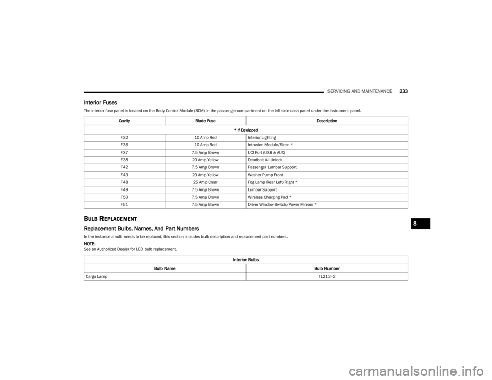
Interior Fuses
The interior fuse panel is located on the Body Control Module (BCM) in the passenger compartment on the left side dash panel under the instrument panel.
BULB REPLACEMENT
Replacement Bulbs, Names, And Part Numbers
In the instance a bulb needs to be replaced, this section includes bulb description and replacement part numbers.
NOTE:See an Authorized Dealer for LED bulb replacement.Cavity
Blade Fuse Description
* If Equipped
F32 10 Amp RedInterior Lighting
F36 10 Amp RedIntrusion Module/Siren *
F37 7.5 Amp BrownUCI Port (USB & AUX)
F38 20 Amp YellowDeadbolt All Unlock
F42 7.5 Amp BrownPassenger Lumbar Support
F43 20 Amp YellowWasher Pump Front
F48 25 Amp ClearFog Lamp Rear Left/Right *
F49 7.5 Amp BrownLumbar Support
F50 7.5 Amp BrownWireless Charging Pad *
F51 7.5 Amp BrownDriver Window Switch/Power Mirrors *
Interior Bulbs
Bulb Name Bulb Number
Cargo Lamp TL212–2
8
23_KL_OM_EN_USC_t.book Page 233
Page 271 of 276
269
Storing Your Vehicle ..................................................... 250
Stuck, Freeing .............................................................. 204
Sun Roof ...................................................................54
, 56
Closing ........................................................................54
Opening ...................................................................... 54
Sun Visor Extension ........................................................34
Sunshade Operation ....................................................... 54
Supplemental Restraint System – Air Bag ................. 167
Sway Control, Trailer .................................................... 150
Symbol Glossary ................................................................ 9
Synthetic Engine Oil ..................................................... 215
System, Remote Starting ................................................18
TTemperature Control, Automatic (ATC) ..........................48
Tie Down Hooks, Cargo...................................................59 Time Delay Headlight ....................................................................41
Tire And Loading Information Placard ........................ 238
Tire Markings................................................................ 235
Tire Safety Information ................................................ 235
Tire Service Kit ................................. 196
, 197, 199, 200
Tires .................................................. 188, 241, 244, 249
Aging (Life Of Tires)................................................. 243 Air Pressure ............................................................. 241
Chains...................................................................... 246Changing ................................................................. 191
Compact Spare ....................................................... 245
General Information ...................................... 241
, 244
High Speed .............................................................. 242
Inflation Pressure ................................................... 241
Jacking..................................................................... 191
Life Of Tires ............................................................. 243
Load Capacity................................................. 238
, 239 Pressure Monitoring System (TPMS) ..............72
, 155
Quality Grading ........................................................ 249
Radial ....................................................................... 242
Replacement ...........................................................243
Rotation....................................................................248 Safety ............................................................. 235
, 241
Sizes ......................................................................... 236
Snow Tires................................................................ 244
Spare Tires..................................................... 244
, 245
Spinning ...................................................................242 Trailer Towing .......................................................... 118
Tread Wear Indicators ............................................. 243Wheel Nut Torque....................................................253
To Open Hood ................................................................. 56
Tongue Weight/Trailer Weight ........................... 115
, 117
Torque Converter Clutch ................................................ 85
Tow Hooks Emergency ............................................................... 206
Towing ........................................................ 114
, 116, 205
Disabled Vehicle ...................................................... 205
Recreational ............................................................120
Towing Behind A Motorhome ....................................... 120
Traction Control ............................................................150
Trailer Sway Control (TSC) ............................................150
Trailer Towing ................................................................ 114 Frontal Area ............................................................. 115
Hitches .....................................................................116
Minimum Requirements ......................................... 117
Tips ...........................................................................119Trailer And Tongue Weight............................ 116
, 117
Weight Carrying Hitch.............................................. 115 Weight Distributing Hitch ........................................ 115
Wiring ....................................................................... 118
Trailer Towing Guide ..................................................... 116
Trailer Weight ................................................................ 116 Transaxle
Automatic .................................................................. 81
Operation ................................................................... 81
Transmission .................................................................. 81 Automatic ......................................................... 81
, 225
Maintenance ........................................................... 225
Transporting Pets ......................................................... 186
Tread Wear Indicators.................................................. 243
Turn Signals ...................................................... 39
, 42, 74
UUconnect Uconnect Settings ............................................ 19, 126
Uconnect Settings Customer Programmable Features .................. 19
, 22
Passive Entry Programming ..................................... 22
Uniform Tire Quality Grades ........................................ 249
Universal Garage Door Opener (HomeLink®) .............. 35
Universal Garage Door Opener (HomeLink®) —
If Equipped
S
............................................................... 35
Untwisting Procedure, Seat Belt.................................. 162
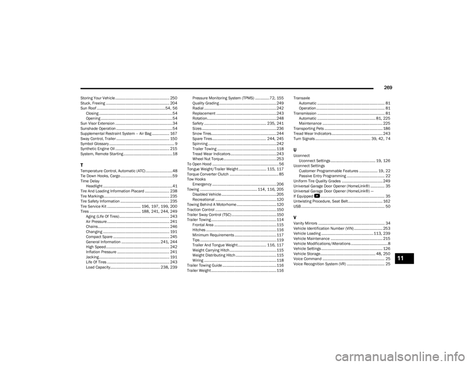
USB.................................................................................. 50
VVanity Mirrors ................................................................. 34
Vehicle Identification Number (VIN) ............................ 253
Vehicle Loading ...................................................113
, 239
Vehicle Maintenance ................................................... 215
Vehicle Modifications/Alterations ....................................8
Vehicle Settings ............................................................ 126
Vehicle Storage...................................................... 48
, 250
Voice Command ............................................................. 25
Voice Recognition System (VR) ..................................... 2511
23_KL_OM_EN_USC_t.book Page 269