fuel pressure JEEP CHEROKEE 2023 Owners Manual
[x] Cancel search | Manufacturer: JEEP, Model Year: 2023, Model line: CHEROKEE, Model: JEEP CHEROKEE 2023Pages: 276, PDF Size: 12.55 MB
Page 6 of 276
4
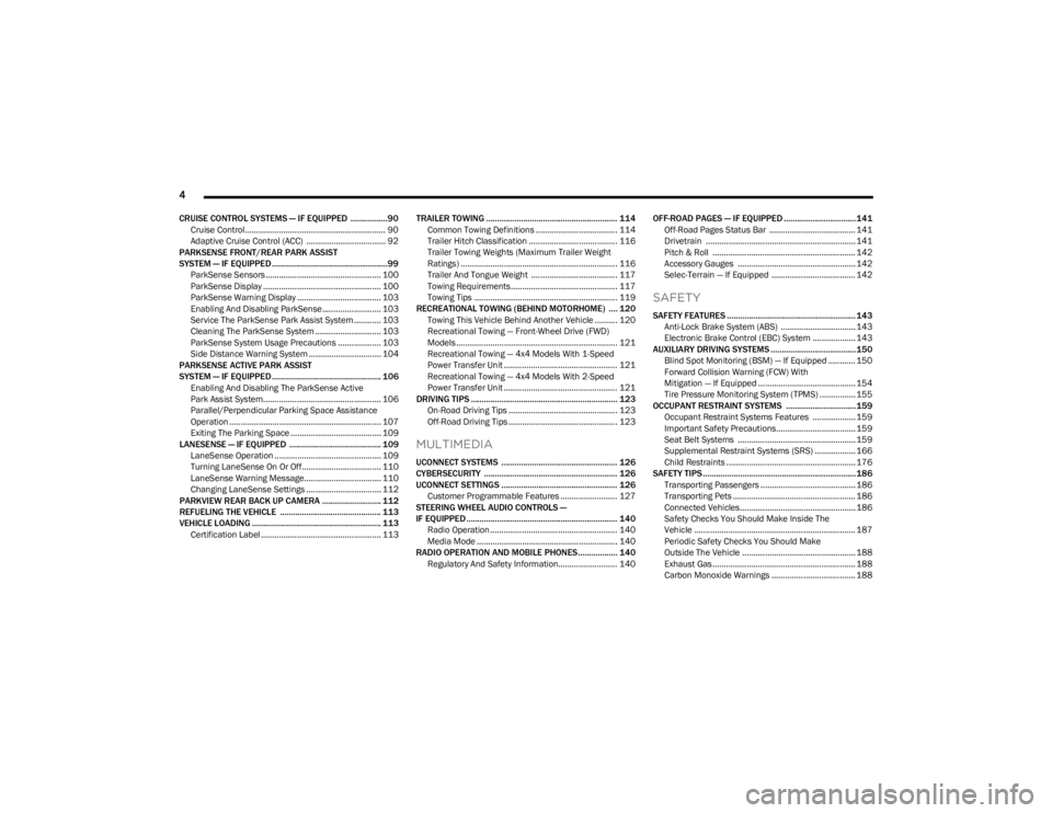
CRUISE CONTROL SYSTEMS — IF EQUIPPED .................90
Cruise Control.............................................................. 90
Adaptive Cruise Control (ACC) ................................... 92
PARKSENSE FRONT/REAR PARK ASSIST
SYSTEM — IF EQUIPPED.....................................................99 ParkSense Sensors ................................................... 100
ParkSense Display .................................................... 100
ParkSense Warning Display ..................................... 103
Enabling And Disabling ParkSense.......................... 103Service The ParkSense Park Assist System ............ 103Cleaning The ParkSense System ............................. 103
ParkSense System Usage Precautions ................... 103Side Distance Warning System ................................ 104
PARKSENSE ACTIVE PARK ASSIST
SYSTEM — IF EQUIPPED.................................................. 106 Enabling And Disabling The ParkSense Active
Park Assist System.................................................... 106
Parallel/Perpendicular Parking Space Assistance
Operation ................................................................... 107
Exiting The Parking Space ........................................ 109
LANESENSE — IF EQUIPPED .......................................... 109 LaneSense Operation ............................................... 109Turning LaneSense On Or Off................................... 110
LaneSense Warning Message.................................. 110Changing LaneSense Settings ................................. 112
PARKVIEW REAR BACK UP CAMERA ........................... 112
REFUELING THE VEHICLE .............................................. 113
VEHICLE LOADING ........................................................... 113 Certification Label ..................................................... 113 TRAILER TOWING ............................................................ 114
Common Towing Definitions .................................... 114Trailer Hitch Classification ....................................... 116
Trailer Towing Weights (Maximum Trailer Weight
Ratings) ..................................................................... 116
Trailer And Tongue Weight ...................................... 117
Towing Requirements............................................... 117
Towing Tips ............................................................... 119
RECREATIONAL TOWING (BEHIND MOTORHOME) .... 120 Towing This Vehicle Behind Another Vehicle .......... 120
Recreational Towing — Front-Wheel Drive (FWD)
Models ....................................................................... 121Recreational Towing — 4x4 Models With 1-Speed
Power Transfer Unit .................................................. 121Recreational Towing — 4x4 Models With 2-Speed
Power Transfer Unit .................................................. 121
DRIVING TIPS ................................................................... 123 On-Road Driving Tips ................................................ 123
Off-Road Driving Tips ................................................ 123
MULTIMEDIA
UCONNECT SYSTEMS ..................................................... 126
CYBERSECURITY ............................................................. 126
UCONNECT SETTINGS ..................................................... 126 Customer Programmable Features ......................... 127
STEERING WHEEL AUDIO CONTROLS —
IF EQUIPPED ..................................................................... 140 Radio Operation ........................................................ 140Media Mode .............................................................. 140
RADIO OPERATION AND MOBILE PHONES.................. 140 Regulatory And Safety Information.......................... 140 OFF-ROAD PAGES — IF EQUIPPED .................................141
Off-Road Pages Status Bar ...................................... 141Drivetrain .................................................................. 141
Pitch & Roll ............................................................... 142
Accessory Gauges .................................................... 142
Selec-Terrain — If Equipped ..................................... 142
SAFETY
SAFETY FEATURES ...........................................................143 Anti-Lock Brake System (ABS) ................................. 143
Electronic Brake Control (EBC) System ................... 143
AUXILIARY DRIVING SYSTEMS .......................................150 Blind Spot Monitoring (BSM) — If Equipped ............ 150
Forward Collision Warning (FCW) With
Mitigation — If Equipped ........................................... 154
Tire Pressure Monitoring System (TPMS) ................ 155
OCCUPANT RESTRAINT SYSTEMS ................................159 Occupant Restraint Systems Features ................... 159
Important Safety Precautions................................... 159
Seat Belt Systems .................................................... 159
Supplemental Restraint Systems (SRS) .................. 166Child Restraints ......................................................... 176
SAFETY TIPS......................................................................186 Transporting Passengers .......................................... 186
Transporting Pets ...................................................... 186Connected Vehicles................................................... 186
Safety Checks You Should Make Inside The
Vehicle ....................................................................... 187
Periodic Safety Checks You Should Make
Outside The Vehicle .................................................. 188
Exhaust Gas ............................................................... 188
Carbon Monoxide Warnings ..................................... 188
23_KL_OM_EN_USC_t.book Page 4
Page 7 of 276
5
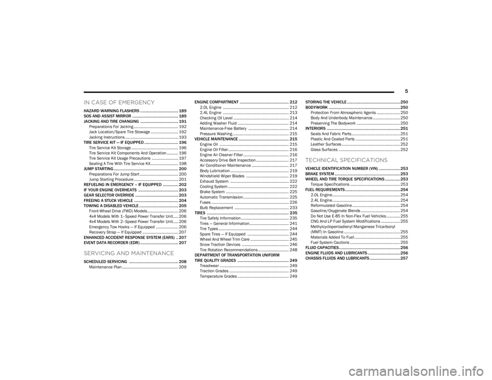
IN CASE OF EMERGENCY
HAZARD WARNING FLASHERS ..................................... 189
SOS AND ASSIST MIRROR ............................................. 189
JACKING AND TIRE CHANGING ..................................... 191 Preparations For Jacking .......................................... 192
Jack Location/Spare Tire Stowage .......................... 192Jacking Instructions .................................................. 193
TIRE SERVICE KIT — IF EQUIPPED ................................. 196 Tire Service Kit Storage ............................................ 196
Tire Service Kit Components And Operation ........... 196Tire Service Kit Usage Precautions ......................... 197Sealing A Tire With Tire Service Kit .......................... 198
JUMP STARTING ............................................................... 200 Preparations For Jump Start .................................... 200
Jump Starting Procedure .......................................... 201
REFUELING IN EMERGENCY – IF EQUIPPED ............... 202
IF YOUR ENGINE OVERHEATS ....................................... 203
GEAR SELECTOR OVERRIDE .......................................... 203
FREEING A STUCK VEHICLE ........................................... 204
TOWING A DISABLED VEHICLE ...................................... 205 Front-Wheel Drive (FWD) Models ............................. 206
4x4 Models With 1–Speed Power Transfer Unit..... 2064x4 Models With 2–Speed Power Transfer Unit..... 206Emergency Tow Hooks — If Equipped ..................... 206
Recovery Strap — If Equipped .................................. 207
ENHANCED ACCIDENT RESPONSE SYSTEM (EARS) .. 207
EVENT DATA RECORDER (EDR) ..................................... 207
SERVICING AND MAINTENANCE
SCHEDULED SERVICING ................................................ 208 Maintenance Plan ..................................................... 209 ENGINE COMPARTMENT ................................................ 212
2.0L Engine .............................................................. 212
2.4L Engine .............................................................. 213
Checking Oil Level .................................................... 214
Adding Washer Fluid ................................................ 214
Maintenance-Free Battery ...................................... 214
Pressure Washing ..................................................... 215
VEHICLE MAINTENANCE ................................................. 215 Engine Oil ................................................................. 215Engine Oil Filter ......................................................... 216Engine Air Cleaner Filter ........................................... 216Accessory Drive Belt Inspection............................... 217
Air Conditioner Maintenance ................................... 217Body Lubrication ....................................................... 219
Windshield Wiper Blades ........................................ 219
Exhaust System ....................................................... 222
Cooling System ......................................................... 222Brake System ........................................................... 225
Automatic Transmission........................................... 225Fuses ......................................................................... 226
Bulb Replacement ................................................... 233
TIRES ................................................................................ 235 Tire Safety Information ............................................. 235
Tires — General Information..................................... 241
Tire Types .................................................................. 244
Spare Tires — If Equipped ....................................... 244
Wheel And Wheel Trim Care .................................... 245Snow Traction Devices ............................................ 246
Tire Rotation Recommendations ............................. 248
DEPARTMENT OF TRANSPORTATION UNIFORM
TIRE QUALITY GRADES .................................................. 249 Treadwear ................................................................. 249Traction Grades ........................................................ 249Temperature Grades ................................................ 249 STORING THE VEHICLE ....................................................250
BODYWORK ......................................................................250
Protection From Atmospheric Agents ...................... 250
Body And Underbody Maintenance.......................... 250
Preserving The Bodywork ......................................... 250
INTERIORS ........................................................................ 251 Seats And Fabric Parts.............................................. 251Plastic And Coated Parts .......................................... 251
Leather Surfaces ....................................................... 252
Glass Surfaces .......................................................... 252
TECHNICAL SPECIFICATIONS
VEHICLE IDENTIFICATION NUMBER (VIN) ..................... 253
BRAKE SYSTEM ................................................................ 253
WHEEL AND TIRE TORQUE SPECIFICATIONS ...............253 Torque Specifications ............................................... 253
FUEL REQUIREMENTS......................................................254 2.0L Engine................................................................ 254
2.4L Engine................................................................ 254
Reformulated Gasoline ............................................. 254Gasoline/Oxygenate Blends ..................................... 254
Do Not Use E-85 In Non-Flex Fuel Vehicles ............. 255
CNG And LP Fuel System Modifications .................. 255Methylcyclopentadienyl Manganese Tricarbonyl
(MMT) In Gasoline ..................................................... 255Materials Added To Fuel ........................................... 255
Fuel System Cautions ............................................... 255
FLUID CAPACITIES............................................................256
ENGINE FLUIDS AND LUBRICANTS ................................256
CHASSIS FLUIDS AND LUBRICANTS ..............................257
23_KL_OM_EN_USC_t.book Page 5
Page 12 of 276
10
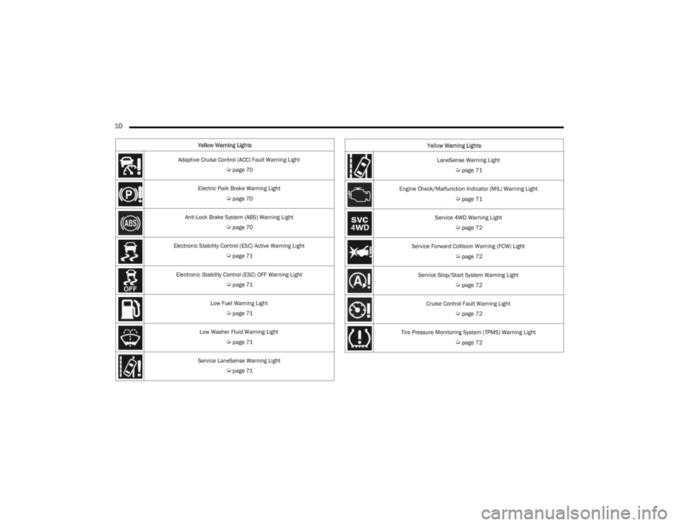
Yellow Warning Lights
Adaptive Cruise Control (ACC) Fault Warning Light
Úpage 70
Electric Park Brake Warning Light
Úpage 70
Anti-Lock Brake System (ABS) Warning Light
Úpage 70
Electronic Stability Control (ESC) Active Warning Light
Úpage 71
Electronic Stability Control (ESC) OFF Warning Light
Úpage 71
Low Fuel Warning Light
Úpage 71
Low Washer Fluid Warning Light
Úpage 71
Service LaneSense Warning Light
Úpage 71
LaneSense Warning Light
Úpage 71
Engine Check/Malfunction Indicator (MIL) Warning Light
Úpage 71
Service 4WD Warning Light
Úpage 72
Service Forward Collision Warning (FCW) Light
Úpage 72
Service Stop/Start System Warning Light
Úpage 72
Cruise Control Fault Warning Light
Úpage 72
Tire Pressure Monitoring System (TPMS) Warning Light
Úpage 72
Yellow Warning Lights
23_KL_OM_EN_USC_t.book Page 10
Page 67 of 276
GETTING TO KNOW YOUR INSTRUMENT PANEL65
Speedometer
Push and release the up or down arrow button
until the speedometer menu icon is displayed in the
instrument cluster display. Push and release the OK
button to toggle units, mph or km/h (If Equipped), of the
speedometer.
Vehicle Info
Push and release the up or down arrow button
until the Vehicle Info menu icon is displayed in the
instrument cluster display. Push and release the left or
right arrow button to scroll through the information
submenus and push and release the OK button to select
or reset the submenus.
Tire Pressure : This menu option will display the current
tire pressure. A low tire will be highlighted in red for the
7 inch cluster and it will be highlighted in white text for
the 3.5 inch cluster.
Coolant Temperature : This menu option will display the
current coolant temperature of the vehicle.
Transmission Temperature : This menu will display the
current transmission temperature of the vehicle.
Oil Temperature : This menu option will display the
current oil temperature level of the vehicle.
Oil Life: This menu option will display the current oil life
of the vehicle.
Battery Voltage : This menu option will display the
current voltage level of the battery.
Driver Assist
Push and release the up or down arrow button
until the Driver Assist menu title is highlighted in the
instrument cluster display.
Adaptive Cruise Control (ACC) Menu — If Equipped
The instrument cluster display displays the current ACC
and LaneSense system settings. The information
displayed depends on the status of ACC and LaneSense.
Push the ACC on/off button (located on the steering
wheel) until one of the following displays in the instrument
cluster display:
Adaptive Cruise Control Off
When ACC is deactivated, and LaneSense is OFF, the
display will read “Adaptive Cruise Control Off.”
Adaptive Cruise Control Ready
When ACC is activated but the vehicle speed setting has
not been selected, the display will read “Adaptive Cruise
Control Ready.”
Push and release the SET + or the SET- button (located on
the steering wheel) and the following will display in the
instrument cluster display:
ACC SET
When ACC is set, the set speed will display in the
instrument cluster.
The ACC screen may display once again if any ACC activity
occurs, which may include any of the following:
Distance Setting Change
System Cancel
Driver Override
System Off
ACC Proximity Warning
ACC Unavailable Warning
NOTE:The instrument cluster display will return to the last
display selected after five seconds of no ACC display
activity
Úpage 92.
LaneSense — If Equipped
The instrument cluster display displays the current
LaneSense system settings. The information displayed
depends on LaneSense system status and the conditions
that need to be met
Úpage 109.
Fuel Economy
Push and release the up or down arrow button
until the Fuel Economy menu title is displayed in the
instrument cluster display. Toggle the left or right
arrow button to select the screen with or without current
fuel economy display. Push and hold the OK button to
reset average fuel economy feature.
Range – The display shows the estimated distance (mi
or km) that can be traveled with the fuel remaining in
the tank. When the Range value is less than 10 miles
(16 km) estimated driving distance, the Range display
will change to a “LOW FUEL” message. Adding a signif -
icant amount of fuel to the vehicle will turn off the “LOW
FUEL” message and a new Range value will display.
Range cannot be reset through the OK button.
3
23_KL_OM_EN_USC_t.book Page 65
Page 74 of 276
72GETTING TO KNOW YOUR INSTRUMENT PANEL
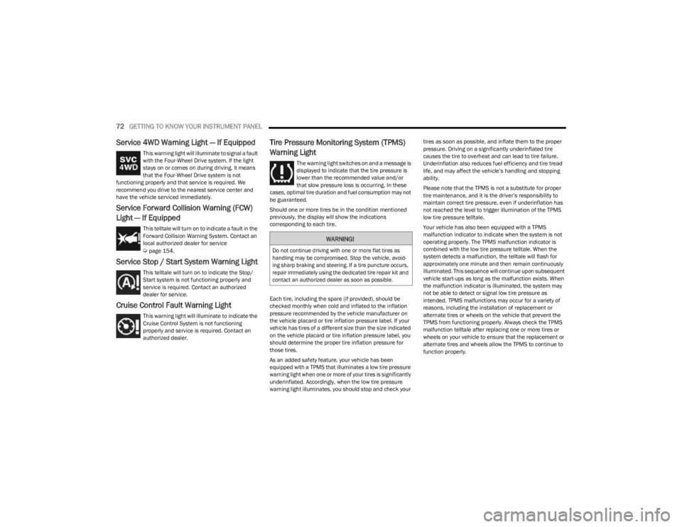
Service 4WD Warning Light — If Equipped
This warning light will illuminate to signal a fault
with the Four-Wheel Drive system. If the light
stays on or comes on during driving, it means
that the Four-Wheel Drive system is not
functioning properly and that service is required. We
recommend you drive to the nearest service center and
have the vehicle serviced immediately.
Service Forward Collision Warning (FCW)
Light — If Equipped
This telltale will turn on to indicate a fault in the
Forward Collision Warning System. Contact an
local authorized dealer for service
Úpage 154.
Service Stop / Start System Warning Light
This telltale will turn on to indicate the Stop/
Start system is not functioning properly and
service is required. Contact an authorized
dealer for service.
Cruise Control Fault Warning Light
This warning light will illuminate to indicate the
Cruise Control System is not functioning
properly and service is required. Contact an
authorized dealer.
Tire Pressure Monitoring System (TPMS)
Warning Light
The warning light switches on and a message is
displayed to indicate that the tire pressure is
lower than the recommended value and/or
that slow pressure loss is occurring. In these
cases, optimal tire duration and fuel consumption may not
be guaranteed.
Should one or more tires be in the condition mentioned
previously, the display will show the indications
corresponding to each tire.
Each tire, including the spare (if provided), should be
checked monthly when cold and inflated to the inflation
pressure recommended by the vehicle manufacturer on
the vehicle placard or tire inflation pressure label. If your
vehicle has tires of a different size than the size indicated
on the vehicle placard or tire inflation pressure label, you
should determine the proper tire inflation pressure for
those tires.
As an added safety feature, your vehicle has been
equipped with a TPMS that illuminates a low tire pressure
warning light when one or more of your tires is significantly
underinflated. Accordingly, when the low tire pressure
warning light illuminates, you should stop and check your tires as soon as possible, and inflate them to the proper
pressure. Driving on a significantly underinflated tire
causes the tire to overheat and can lead to tire failure.
Underinflation also reduces fuel efficiency and tire tread
life, and may affect the vehicle’s handling and stopping
ability.
Please note that the TPMS is not a substitute for proper
tire maintenance, and it is the driver’s responsibility to
maintain correct tire pressure, even if underinflation has
not reached the level to trigger illumination of the TPMS
low tire pressure telltale.
Your vehicle has also been equipped with a TPMS
malfunction indicator to indicate when the system is not
operating properly. The TPMS malfunction indicator is
combined with the low tire pressure telltale. When the
system detects a malfunction, the telltale will flash for
approximately one minute and then remain continuously
illuminated. This sequence will continue upon subsequent
vehicle start-ups as long as the malfunction exists. When
the malfunction indicator is illuminated, the system may
not be able to detect or signal low tire pressure as
intended. TPMS malfunctions may occur for a variety of
reasons, including the installation of replacement or
alternate tires or wheels on the vehicle that prevent the
TPMS from functioning properly. Always check the TPMS
malfunction telltale after replacing one or more tires or
wheels on your vehicle to ensure that the replacement or
alternate tires and wheels allow the TPMS to continue to
function properly.
WARNING!
Do not continue driving with one or more flat tires as
handling may be compromised. Stop the vehicle, avoid
-
ing sharp braking and steering. If a tire puncture occurs,
repair immediately using the dedicated tire repair kit and
contact an authorized dealer as soon as possible.
23_KL_OM_EN_USC_t.book Page 72
Page 75 of 276
GETTING TO KNOW YOUR INSTRUMENT PANEL73
YELLOW INDICATOR LIGHTS
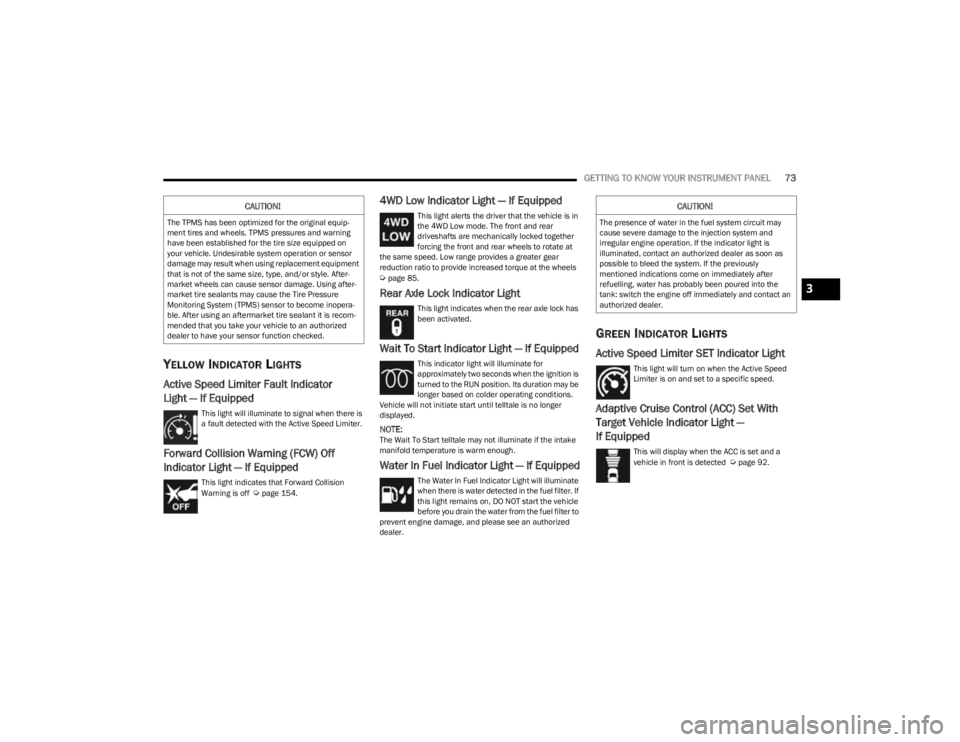
Active Speed Limiter Fault Indicator
Light — If Equipped
This light will illuminate to signal when there is
a fault detected with the Active Speed Limiter.
Forward Collision Warning (FCW) Off
Indicator Light — If Equipped
This light indicates that Forward Collision
Warning is off Úpage 154.
4WD Low Indicator Light — If Equipped
This light alerts the driver that the vehicle is in
the 4WD Low mode. The front and rear
driveshafts are mechanically locked together
forcing the front and rear wheels to rotate at
the same speed. Low range provides a greater gear
reduction ratio to provide increased torque at the wheels
Úpage 85.
Rear Axle Lock Indicator Light
This light indicates when the rear axle lock has
been activated.
Wait To Start Indicator Light — If Equipped
This indicator light will illuminate for
approximately two seconds when the ignition is
turned to the RUN position. Its duration may be
longer based on colder operating conditions.
Vehicle will not initiate start until telltale is no longer
displayed.
NOTE:The Wait To Start telltale may not illuminate if the intake
manifold temperature is warm enough.
Water In Fuel Indicator Light — If Equipped
The Water In Fuel Indicator Light will illuminate
when there is water detected in the fuel filter. If
this light remains on, DO NOT start the vehicle
before you drain the water from the fuel filter to
prevent engine damage, and please see an authorized
dealer.
GREEN INDICATOR LIGHTS
Active Speed Limiter SET Indicator Light
This light will turn on when the Active Speed
Limiter is on and set to a specific speed.
Adaptive Cruise Control (ACC) Set With
Target Vehicle Indicator Light —
If Equipped
This will display when the ACC is set and a
vehicle in front is detected Úpage 92.
CAUTION!
The TPMS has been optimized for the original equip -
ment tires and wheels. TPMS pressures and warning
have been established for the tire size equipped on
your vehicle. Undesirable system operation or sensor
damage may result when using replacement equipment
that is not of the same size, type, and/or style. After -
market wheels can cause sensor damage. Using after -
market tire sealants may cause the Tire Pressure
Monitoring System (TPMS) sensor to become inopera -
ble. After using an aftermarket tire sealant it is recom -
mended that you take your vehicle to an authorized
dealer to have your sensor function checked.
CAUTION!
The presence of water in the fuel system circuit may
cause severe damage to the injection system and
irregular engine operation. If the indicator light is
illuminated, contact an authorized dealer as soon as
possible to bleed the system. If the previously
mentioned indications come on immediately after
refuelling, water has probably been poured into the
tank: switch the engine off immediately and contact an
authorized dealer.
3
23_KL_OM_EN_USC_t.book Page 73
Page 91 of 276
STARTING AND OPERATING89
NOTE:
Even if the power steering assistance is no longer oper -
ational, it is still possible to steer the vehicle. Under
these conditions there will be a substantial increase in
steering effort, especially at low speeds and during
parking maneuvers.
If the condition persists, see an authorized dealer for
service.
STOP/START SYSTEM
The Stop/Start system was designed to reduce fuel
consumption. The system will stop the engine
automatically during a vehicle stop if the required
conditions are met. Releasing the brake pedal or pressing
the accelerator pedal will automatically restart the engine.
This vehicle has been upgraded with a heavy-duty battery,
starter, as well as other engine parts, to handle the
additional engine starts.
AUTOSTOP MODE
The Stop/Start feature is enabled after every normal
customer engine start. At that time, the system will go into
STOP/START READY.
To Activate The Autostop Mode, The Following Must Occur:
The system must be in STOP/START READY state. A
“STOP/START READY” message will be displayed in the
instrument cluster display within the Stop/Start
section
Úpage 63.
The vehicle must be completely stopped.
The gear selector must be in a forward gear and the
brake pedal pressed. The engine will shut down, the tachometer will move to the
zero position, and the Stop/Start indicator light will
illuminate indicating you are in Autostop. Customer
settings will be maintained upon return to an
engine-running condition.
POSSIBLE REASONS THE ENGINE DOES
N
OT AUTOSTOP
Prior to engine shut down, the system will check many
safety and comfort conditions to see if they are fulfilled.
Detailed information about the operation of the Stop/Start
system may be viewed in the instrument cluster display
Stop/Start Screen. In the following situations, the engine
will not stop:
Driver’s seat belt is not buckled
Driver’s door is not closed
Battery temperature is too warm or cold
Battery charge is low
The vehicle is on a steep grade
Cabin heating or cooling is in process and an accept -
able cabin temperature has not been achieved
HVAC is set to full defrost mode at a high blower speed
HVAC is set to MAX A/C
Engine has not reached normal operating temperature
The transmission is not in a forward or reverse gear
Hood is open
Brake pedal is not pressed with sufficient pressure with
vehicle in DRIVE (D) position
Accelerator pedal input
Engine temperature is too high
5 mph (8 km/h) threshold has not been achieved from
previous Autostop
Steering angle is beyond threshold
It may be possible for the vehicle to be driven several
times without the Stop/Start system going into a STOP/
START READY state under more extreme conditions of the
items listed previously.TO START THE ENGINE WHILE IN
A
UTOSTOP MODE
While in a forward gear, the engine will start when the
brake pedal is released or the accelerator pedal is
pressed. The transmission will automatically re-engage
upon engine restart.
Conditions That Will Cause The Engine To Start
Automatically While In Autostop Mode:
The transmission gear selector is moved out of DRIVE,
except in the PARK position
To maintain cabin temperature comfort
HVAC is set to full defrost mode
HVAC system temperature or fan speed is manually
adjusted
Battery voltage drops too low
Stop/Start OFF switch is pushed
A Stop/Start system error occurs
Steering wheel is turned beyond threshold
4
23_KL_OM_EN_USC_t.book Page 89
Page 116 of 276
114STARTING AND OPERATING
Payload
The payload of a vehicle is defined as the allowable load
weight a truck can carry, including the weight of the driver,
all passengers, options and cargo.
Gross Axle Weight Rating (GAWR)
The GAWR is the maximum permissible load on the front
and rear axles. The load must be distributed in the cargo
area so that the GAWR of each axle is not exceeded.
Each axle GAWR is determined by the components in the
system with the lowest load carrying capacity (axle,
springs, tires or wheels). Heavier axles, or suspension
components sometimes specified by purchasers for
increased durability, do not necessarily increase the
vehicle's GVWR.
Tire Size
The tire size on the Vehicle Certification Label represents
the actual tire size on your vehicle. Replacement tires
must be equal to the load capacity of this tire size.
Rim Size
This is the rim size that is appropriate for the tire size
listed.
Inflation Pressure
This is the cold tire inflation pressure for your vehicle for
all loading conditions up to full GAWR.
Curb Weight
The curb weight of a vehicle is defined as the total weight
of the vehicle with all fluids, including vehicle fuel, at full
capacity conditions, and with no occupants or cargo
loaded into the vehicle. The front and rear curb weight
values are determined by weighing your vehicle on a
commercial scale before any occupants or cargo are
added.
Loading
The actual total weight and the weight of the front and rear
of your vehicle at the ground can best be determined by
weighing it when it is loaded and ready for operation.
The entire vehicle should first be weighed on a commercial
scale to ensure that the GVWR has not been exceeded.
The weight on the front and rear of the vehicle should then
be determined separately to be sure that the load is
properly distributed over the front and rear axle. Weighing
the vehicle may show that the GAWR of either the front or
rear axles has been exceeded but the total load is within
the specified GVWR. If so, weight must be shifted from
front to rear or rear to front as appropriate until the
specified weight limitations are met. Store the heavier
items down low and be sure that the weight is distributed
equally. Stow all loose items securely before driving.
Improper weight distributions can have an adverse effect
on the way your vehicle steers and handles and the way
the brakes operate.TRAILER TOWING
In this section you will find safety tips and information on
limits to the type of towing you can reasonably do with your
vehicle. Before towing a trailer, carefully review this
information to tow your load as efficiently and safely as
possible.
To maintain the New Vehicle Limited Warranty coverage,
follow the requirements and recommendations in this
manual concerning vehicles used for trailer towing.
COMMON TOWING DEFINITIONS
The following trailer towing related definitions will assist
you in understanding the following information:
Gross Vehicle Weight Rating (GVWR)
The GVWR is the total allowable weight of your vehicle.
This includes driver, passengers, cargo, and tongue
weight. The total load must be limited so that you do not
exceed the GVWR
Úpage 113.
WARNING!
Do not load your vehicle any heavier than the GVWR or
the maximum front and rear GAWR. If you do, parts on
your vehicle can break, or it can change the way your
vehicle handles. This could cause you to lose control.
Overloading can shorten the life of your vehicle.
23_KL_OM_EN_USC_t.book Page 114
Page 131 of 276
MULTIMEDIA129
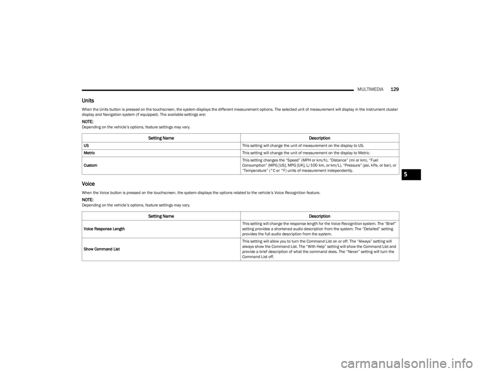
Units
Voice
When the Units button is pressed on the touchscreen, the system displays the different measurement options. The selected unit of measurement will display in the instrument cluster
display and Navigation system (if equipped). The available settings are:
NOTE:Depending on the vehicle’s options, feature settings may vary.
Setting Name Description
US This setting will change the unit of measurement on the display to US.
Metric This setting will change the unit of measurement on the display to Metric.
Custom This setting changes the “Speed” (MPH or km/h), “Distance” (mi or km), “Fuel
Consumption” (MPG [US], MPG [UK], L/100 km, or km/L), “Pressure” (psi, kPa, or bar), or
“Temperature” (°C or °F) units of measurement independently.
When the Voice button is pressed on the touchscreen, the system displays the options related to the vehicle’s Voice Recognition feature.
NOTE:Depending on the vehicle’s options, feature settings may vary.
Setting Name
Description
Voice Response Length This setting will change the response length for the Voice Recognition system. The “Brief”
setting provides a shortened audio description from the system. The “Detailed” setting
provides the full audio description from the system.
Show Command List This setting will allow you to turn the Command List on or off. The “Always” setting will
always show the Command List. The “With Help” setting will show the Command List and
provide a brief description of what the command does. The “Never” setting will turn the
Command List off.
5
23_KL_OM_EN_USC_t.book Page 129
Page 158 of 276
156SAFETY
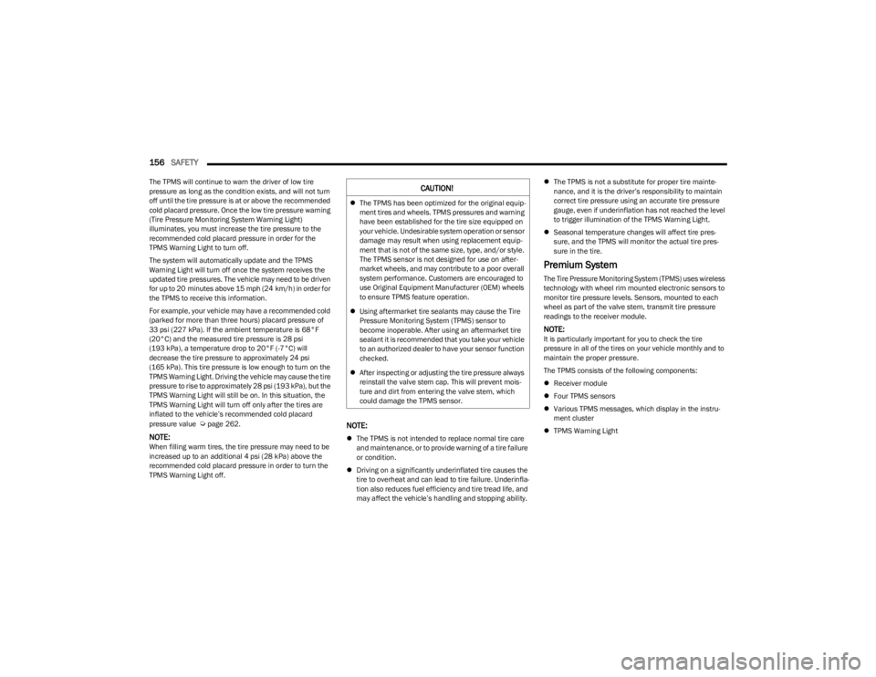
The TPMS will continue to warn the driver of low tire
pressure as long as the condition exists, and will not turn
off until the tire pressure is at or above the recommended
cold placard pressure. Once the low tire pressure warning
(Tire Pressure Monitoring System Warning Light)
illuminates, you must increase the tire pressure to the
recommended cold placard pressure in order for the
TPMS Warning Light to turn off.
The system will automatically update and the TPMS
Warning Light will turn off once the system receives the
updated tire pressures. The vehicle may need to be driven
for up to 20 minutes above 15 mph (24 km/h) in order for
the TPMS to receive this information.
For example, your vehicle may have a recommended cold
(parked for more than three hours) placard pressure of
33 psi (227 kPa). If the ambient temperature is 68°F
(20°C) and the measured tire pressure is 28 psi
(193 kPa), a temperature drop to 20°F (-7°C) will
decrease the tire pressure to approximately 24 psi
(165 kPa). This tire pressure is low enough to turn on the
TPMS Warning Light. Driving the vehicle may cause the tire
pressure to rise to approximately 28 psi (193 kPa), but the
TPMS Warning Light will still be on. In this situation, the
TPMS Warning Light will turn off only after the tires are
inflated to the vehicle’s recommended cold placard
pressure value
Úpage 262.
NOTE:When filling warm tires, the tire pressure may need to be
increased up to an additional 4 psi (28 kPa) above the
recommended cold placard pressure in order to turn the
TPMS Warning Light off.
NOTE:
The TPMS is not intended to replace normal tire care
and maintenance, or to provide warning of a tire failure
or condition.
Driving on a significantly underinflated tire causes the
tire to overheat and can lead to tire failure. Underinfla -
tion also reduces fuel efficiency and tire tread life, and
may affect the vehicle’s handling and stopping ability.
The TPMS is not a substitute for proper tire mainte -
nance, and it is the driver’s responsibility to maintain
correct tire pressure using an accurate tire pressure
gauge, even if underinflation has not reached the level
to trigger illumination of the TPMS Warning Light.
Seasonal temperature changes will affect tire pres -
sure, and the TPMS will monitor the actual tire pres -
sure in the tire.
Premium System
The Tire Pressure Monitoring System (TPMS) uses wireless
technology with wheel rim mounted electronic sensors to
monitor tire pressure levels. Sensors, mounted to each
wheel as part of the valve stem, transmit tire pressure
readings to the receiver module.
NOTE:It is particularly important for you to check the tire
pressure in all of the tires on your vehicle monthly and to
maintain the proper pressure.
The TPMS consists of the following components:
Receiver module
Four TPMS sensors
Various TPMS messages, which display in the instru -
ment cluster
TPMS Warning Light
CAUTION!
The TPMS has been optimized for the original equip -
ment tires and wheels. TPMS pressures and warning
have been established for the tire size equipped on
your vehicle. Undesirable system operation or sensor
damage may result when using replacement equip -
ment that is not of the same size, type, and/or style.
The TPMS sensor is not designed for use on after -
market wheels, and may contribute to a poor overall
system performance. Customers are encouraged to
use Original Equipment Manufacturer (OEM) wheels
to ensure TPMS feature operation.
Using aftermarket tire sealants may cause the Tire
Pressure Monitoring System (TPMS) sensor to
become inoperable. After using an aftermarket tire
sealant it is recommended that you take your vehicle
to an authorized dealer to have your sensor function
checked.
After inspecting or adjusting the tire pressure always
reinstall the valve stem cap. This will prevent mois -
ture and dirt from entering the valve stem, which
could damage the TPMS sensor.
23_KL_OM_EN_USC_t.book Page 156