alternator belt JEEP CJ 1953 User Guide
[x] Cancel search | Manufacturer: JEEP, Model Year: 1953, Model line: CJ, Model: JEEP CJ 1953Pages: 376, PDF Size: 19.96 MB
Page 169 of 376
'Jeep'
UNIVERSAL
SERIES SERVICE
MANUAL
G
cation period. It is
good
preventive maintenance to
replace a badly frayed, worn or cracked fan belt
before it breaks in operation.
To
replace the fan belt,
loosen
the attaching
bolts
at each generator or alternator brace-to-engine mounting and pivot the alternator or generator to
ward
the
engine
to gain slack needed to install the new belt Remove the old belt. Position the new
belt over the fan pulley, over the crankshaft pulley,
then over the generator or alternator pulley.
Pull
the generator or alternator away from the
engine
until
belt tension is
firm.
Then tighten the generator
or
alternator mounting
bolts
and check the tension
as indicated above. Reset the generator or alternator as necessary for correct belt tension.
Finally,
torque
the generator or alternator mounting
bolts
25 to 35 lb-ft. [3,4 a 4,8 kg-m.].
Note:
On the Dauntless V-6
engine
when adjusting
the fan belt tension, the alternator mounting
bolts
should be torqued 30 to 40 lb-ft. [4,14 to 5,53
kg-m.].
If a fan belt tension
gauge
(W-283) is
avail
able, proper tension should be 80 pounds [36,2 kg.].
G-l
9. Engine Overheating
An
engine
will
not be damaged by high coolant
temperatures unless the coolant boils. The pres
surized
cooling system on the 'Jeep' vehicles raises the boiling point of the coolant solution. Should
overheating be encountered, and the fault is be
lieved to be in the cooling system check for the
following:
a.
Proper coolant level. See
Filling
Cooling Sys
tem Par. G-2.
b. Poor air flow.
Check
for dirty radiator core. (See Radiator Par. G-5).
Check
for faulty belt
pulley operation, worn or
loose
fan belt, or dam aged fan.
Clean,
repair, replace or adjust as neces
sary.
c. Foaming coolant.
Check
for air leaks at water
pump,
hose
connection and filler cap. Tighten, re
pair
or replace as necessary.
d.
Surging or "after boil".
Check
pressure cap and
replace if valves or gasket are faulty.
e.
External
leaks.
Check
the following for leaks:
Hoses and clamps, water pump, radiator, head gas
ket, core plugs and drain cocks, as well as the cylin der head or block for
cracks.
f.
Internal
leaks.
Check
for faulty head gasket,
cracked
cylinder head or block.
g. Poor coolant flow.
Check
hose
condition, water pump, fan belt, and repair or replace as necessary. Inspect block for rust or scale, and clean and flush
the system, if necessary.
h.
Check
the temperature
gauge.
169
Page 195 of 376
'Jeep*
UNIVERSAL
SERIES SERVICE
MANUAL
H
no soldering or unsoldering of leads; two complete
rectifying
diode assemblies
which
eliminate the need
for removing and replacing individual diodes; a
corpplete isolation diode assembly; and a rotor
assembly complete with shaft,
pole
pieces, field
coil,
and slip rings.
The
transistorized
voltage
regulator is an electronic
switching device. It
senses
the
voltage
appearing
at the auxiliary terminal of the alternator and
supplies the necessary field current for maintaining
the system
voltage
at the output terminal. The
output current is determined by the battery electri
cal
load; such as headlights, heater, etc.
The
transistorized
voltage
regulator is a sealed
unit,
has no adjustments, and must be replaced
as a complete unit.
H-64. ALTERNATOR
PRECAUTIONS
The
following precautions must be observed to
prevent damage to the alternator and regulator.
a.
Never reverse battery connections. Always
check
the battery polarity with a voltmeter before
any
connections are made to be sure that all con
nections correspond to the battery ground polarity of the vehicle.
b.
Booster batteries for starting must be properly
connected. Make sure that the negative cable of
the booster battery is connected to the negative
terminal
of the battery in the vehicle. The positive
cable of the booster battery should be connected
to the positive terminal of the battery in the
vehicle.
c.
Disconnect the battery cables before using a fast charger.
d.
Never use a fast charger as a booster for
starting
the vehicle.
e.
Never disconnect the
voltage
regulator while
the
engine
is running.
f.
Do not ground the alternator output terminal.
g.
Do not operate the alternator on an open
circuit
with
the field energized.
h.
Do not attempt to polarize an alternator.
These
precautions are stated here as an aid to
service
personnel. They are also restated at appro
priate
places in the
text
of this section of the
manual.
H-65. ALTERNATOR
CHARGING
SYSTEM SERVICE
Important:
All alternator
tests
for the 35, 40 and
55 amp alternator are the same, however, there is a
difference
between
the location of the various ter
minals
and field current specifications. The field
current
of the 35 amp alternator should be 1.7 to 2.3 amps, 40 and 55 amp alternators should be 1.8
to 2.4 amps, with
full
battery
voltage
applied to
the filed coil. Disassembly and assembly procedures
are
the same for all three alternators.
Terminal
locations and wire harness color
codes
for the 35,
40 and 55 amp alternator are shown in Fig. H-38.
H-66.
Service Diagnosis
In
diagnosing a suspected malfunction of the
alternator
charging system, consideration must
be given to the complete electrical power plant of the vehicle; including the alternator, regulator,
ignition switch, charge indicator lamp, battery,
and
all associated wiring. If it is suspected that the
alternator
is not fully charging the battery and
fulfilling
the electrical requirements of the electrical
system, several checks should be made before
checking
the alternator itself:
Note:
Whenever service is required in connection
with
an alternator problem, the first
step
should be to verify that the wiring harness hook-up is correct
as indicated in Fig. H-38.
a.
Test the condition of the battery and
state
of
charge
(Par. H-2).
If the battery is not fully charged
and
in
good
condition, use a replacement battery
for making alternator system
tests.
Caution:
Make certain that the negative battery
post
is connected to ground when making the
battery installation. Serious damage to the alter
nator
can result if battery polarity is reversed.
b.
Check
fan belt for proper tension (Par.
C-27).
Caution:
To increase belt tension, apply pressure
to alternator front housing only as permanent damage can result if pressure is applied to
rear
housing.
H-67.
Alternator In Vehicle Tests
The
following
tests
are made with the alternator
in
the vehicle with output and regulator connec
tions maintained to the alternator except as noted
in
Fig. H-27 and H-28. The field plug and
voltage
regulator are disconnected for
these
tests.
The
tests
are given in proper order and detail in the
following paragraphs.
a.
Isolation Diode Test: To determine if the isola
tion diode is open or shorted, refer to Par. H-69.
b.
Alternator Output Test: To isolate the trouble
to the alternator or regulator, refer to Par. H-70.
c.
Alternator
Field
Circuit
Test: To determine the condition of the field
circuit
(brushes and rotor),
refer
to Par. H-73.
d.
Brush
Insulation
and Continuity
Test:
To deter
mine the condition of the
brush,
refer to
Par.
H-75.
e.
Rotor In-Vehicle Test: To determine whether
the rotor coil is open or shorted, refer to
Par.
H-73.
f. Any further
tests
must be conducted with the
alternator
removed and disassembled. When this
is done, the condition of the rotor, the rectifying
and
isolation diodes, and the stator can be further
tested.
A
commercial alternator tester Sun
Electric
Model
VAT-20
or equivalent can be used to make all
necessary
tests
on the alternator system. If a com
mercial
tester is used, follow the recommended
testing procedure outlined by the tester manu
facturer.
If
a commercial tester is not available, follow the
testing procedure as outlined in this manual.
H-68.
Test Equipment
a.
Volt Ampere Tester such as Sun
Electric
Model
VAT-20
or equivalent with meter ranges as shown
in
the following list can be used. 195
Page 198 of 376
H
ELECTRICAL
SYSTEM
terminal
and bracket. Test lamp should not light.
If
it
does,
the
brush
is shorted and must be replaced,
b.
Connect one lead of an ohmmeter to field ter
minal
and the other lead to insulated brush. Re
sistance reading should be zero. Move brush and
brush
lead wire to make certain that the brush lead wire connections are not intermittent. Resist
ance reading should not vary when brush and lead
wire
are being moved.
C.
Connect ohmmeter leads to bracket and grounded brush. Resistance reading should be zero.
Repeat same
test
on brush lead wire as described
in
step
b above.
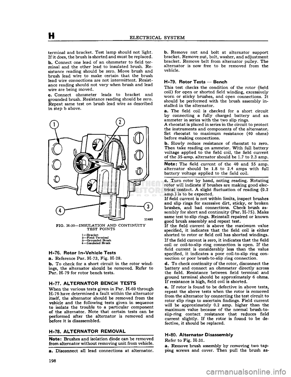
FIG.
H-30—INSULATION
AND
CONTINUITY
TEST
POINTS
1^-Brackct
2—
Field
Terminal
3—
Grounded
Brush
4—
Insulated
Brush
H-76.
Rotor
In-Vehicle
Tests
a.
Reference Par. H-73, Fig. H-28.
b.
To check for a short circuit in the rotor wind
ings, the alternator should be removed. Refer to
Par.
H-79 for rotor bench
tests.
H-77.
ALTERNATOR
BENCH
TESTS
When
the various
tests
given in
Par.
H-69 through
H-76 have determined a fault within the alternator itself, the alternator should be removed from the vehicle and the following
tests
given in
sequence
to isolate the trouble to a particular
component
of the alternator.
Note
that certain
tests
can be
performed after the alternator is removed and
before
it is disassembled.
H-78.
ALTERNATOR
REMOVAL
Note:
Brushes and isolation
diode
can be removed
from
alternator without removing unit from vehicle.
a.
Disconnect all lead connections at alternator.
b.
Remove nut and
bolt
at alternator support
bracket.
Remove nut, bolt, washer, and adjustment
bracket.
Remove belt from alternator pulley. The alternator is now free to be removed from the
vehicle.
H-79.
Rotor Tests
—
Bench
This
test
checks the condition of the rotor (field coil) for
open
or shorted field winding, excessively
worn
or sticky brushes, and
open
connections. It should be performed with the brush assembly in
stalled in the alternator.
a.
The field coil is checked for a short circuit
by connecting a fully charged battery and an ammeter in series with the two slip rings.
A
rheostat is placed in series in the
circuit
to protect
the instruments and
components
of the alternator. Set rheostat to maximum resistance (40 ohms)
before
making connections.
b.
Slowly reduce resistance of rheostat to zero.
Then
take reading on ammeter. With full battery
voltage
applied to the field coil, the field current
of the 35-amp. alternator should be 1.7 to 2.3 amp.
Note:
The field current of the 40 and 55 amp.
alternator should be 1.8 to 2.4 amps with full battery
voltage
applied to the field coil.
c.
Turn
rotor by hand, noting reading. Rotating
rotor
will
indicate if brushes are making
good
elec
trical
contact. A slight fluctuation of reading (0.2
amp.)
is to be expected.
If
field current is not within limits, inspect brushes
and
slip rings for
excessive
dirt, sticky, or broken
brushes, and bad connections.
Check
brush as sembly for short and continuity (Par. H-75). Make
same
test
to slip rings. Reinstall repaired or known
good
brush assembly and repeat
test.
If
the field current is
above
the maximum value
specified, it indicates that the field coil is either
shorted to rotor or field coil has shorted windings.
If
the field current is zero, it indicates that the field
coil
or coil-to-slip ring connection is open. If the field
current
is considerably
less
than the value
specified, it indicates a poor coil-to-slip ring con nection or poor brush-to-slip ring connection.
d.
To check continuity of the rotor, disconnect the
battery and connect an ohmmeter directly across
the field. Resistance
between
field terminal and ground terminal should be approximately 6 ohms.
If
resistance is high, field coil is shorted.
e.
If rotor is found to be
defective
in
above
tests,
repeat the
above
tests
when the rotor is removed
from
the alternator by connecting the
test
circuit
to rotor slip rings to ascertain findings.
Field
current
will
be approximately 0.2 amp. higher than the
maximum
value because of the normal brush-to-
slip-ring
contact resistance that reduces field
current
slightly. If the rotor is found to be de
fective, it should be replaced.
H-80.
Alternator Disassembly
Refer
to Fig. H-31.
a.
Remove brush assembly by removing two tap ping screws and cover. Then pull the brush as- 198
Page 202 of 376
H
ELECTRICAL
SYSTEM
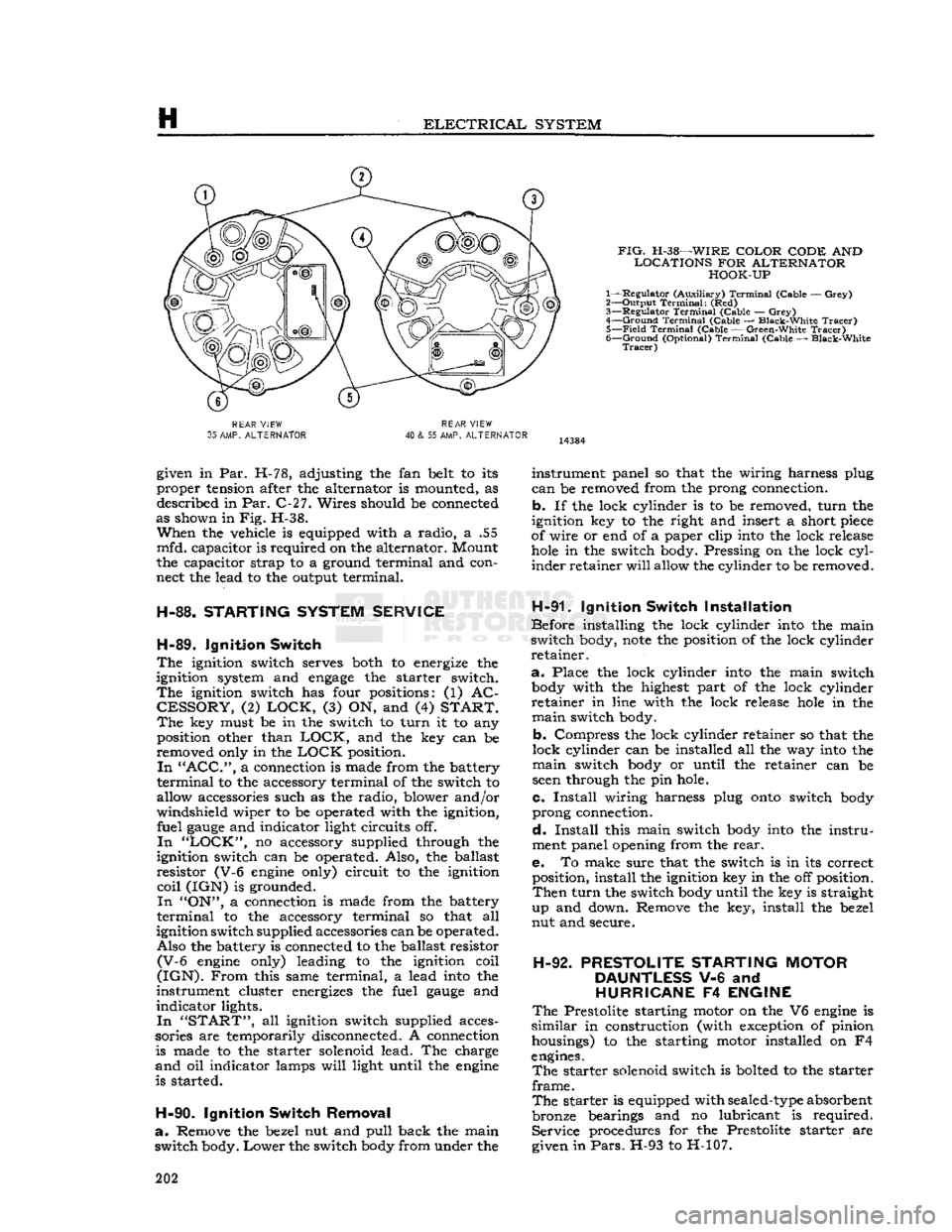
FIG.
H-38—WIRE
COLOR CODE
AND
LOCATIONS
FOR
ALTERNATOR HOOK-UP
1— Regulator (Auxiliary)
Terminal
(Cable —
Grey)
2— Output
Terminal:
(Red)
3—
Regulator
Terminal
(Cable —
Grey)
4—
Ground
Terminal
(Cable — Black-White
Tracer)
5—
Field
Terminal
(Cable — Green-White
Tracer)
6—
Ground
(Optional)
Terminal
(Cable — Black-White
Tracer)
REAR
VIEW
35
AMP.
ALTERNATOR
REAR
VIEW
40
& 55 AMP.
ALTERNATOR
given in Par. H-78, adjusting the fan belt to its
proper tension after the alternator is mounted, as described in Par. C-27. Wires should be connected
as shown in Fig. H-38.
When
the vehicle is equipped with a radio, a .55
mfd. capacitor is required on the alternator. Mount
the capacitor strap to a ground terminal and con
nect the lead to the output terminal.
H-88.
STARTING
SYSTEM
SERVICE
H-89.
Ignition
Switch
The
ignition switch serves both to energize the
ignition system and
engage
the starter switch.
The
ignition switch has four positions: (1) AC
CESSORY,
(2)
LOCK,
(3) ON, and (4)
START. The
key must be in the switch to turn it to any position other than
LOCK,
and the key can be
removed only in the
LOCK
position.
In "ACC",
a connection is made from the battery
terminal
to the accessory terminal of the switch to
allow accessories such as the radio, blower and/or
windshield wiper to be operated with the ignition, fuel
gauge
and indicator light circuits off.
In "LOCK",
no accessory supplied through the
ignition switch can be operated. Also, the ballast
resistor (V-6
engine
only) circuit to the ignition
coil
(IGN) is grounded.
In
"ON", a connection is made from the battery
terminal
to the accessory terminal so that all
ignition switch supplied accessories can be operated. Also the battery is connected to the ballast resistor
(V-6
engine
only) leading to the ignition coil
(IGN).
From
this same terminal, a lead
into
the
instrument cluster energizes the fuel
gauge
and
indicator lights.
In "START",
all ignition switch supplied acces
sories are temporarily disconnected. A connection is made to the starter solenoid lead. The charge
and
oil indicator lamps
will
light until the
engine
is started.
H-90.
Ignition
Switch
Removal
a.
Remove the bezel nut and pull back the main
switch body.
Lower
the switch
body
from under the instrument panel so that the wiring harness plug
can
be removed from the prong connection,
b. If the lock cylinder is to be removed, turn the
ignition key to the right and insert a short
piece
of wire or end of a paper clip
into
the lock release
hole
in the switch body. Pressing on the lock
cyl
inder retainer
will
allow the cylinder to be removed.
H-91.
Ignition
Switch
Installation
Before installing the lock cylinder
into
the main
switch body,
note
the position of the lock cylinder
retainer.
a.
Place the lock cylinder
into
the main switch
body
with the highest part of the lock cylinder
retainer in line with the lock release
hole
in the
main
switch body.
b. Compress the lock cylinder retainer so that the
lock cylinder can be installed all the way
into
the
main
switch
body
or until the retainer can be
seen
through the pin hole.
c.
Install
wiring harness plug
onto
switch
body
prong connection.
d.
Install
this main switch
body
into
the instru
ment panel opening from the
rear.
e. To make sure that the switch is in its correct position, install the ignition key in the off position.
Then
turn the switch
body
until the key is straight
up and down. Remove the key, install the bezel
nut and secure.
H-92.
PRESTOLITE
STARTING
MOTOR
DAUNTLESS
V-6 and
HURRICANE
F4
ENGINE
The
Prestolite starting motor on the V6
engine
is
similar
in construction (with exception of pinion housings) to the starting motor installed on F4
engines.
The
starter solenoid switch is bolted to the starter
frame.
The
starter is equipped with
sealed-type
absorbent
bronze bearings and no lubricant is required. Service procedures for the Prestolite starter are
given in
Pars.
H-93 to H-107. 202
Page 220 of 376
H
ELECTRICAL
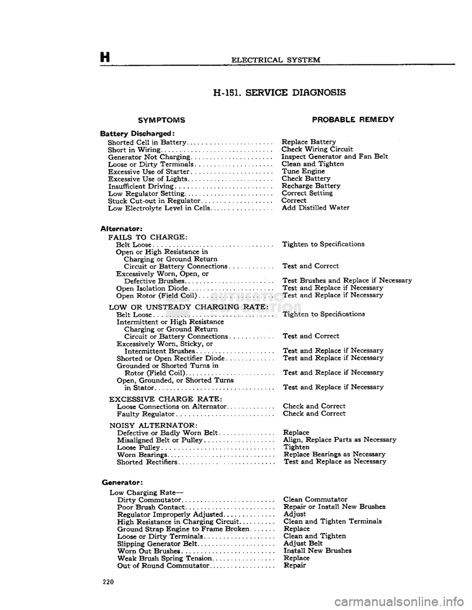
SYSTEM H-15L SERVICE
DIAGNOSIS
SYMPTOMS
Battery
Discha
rged: Shorted
Cell
in Battery......... Short in Wiring..
•
Generator Not Charging ,
Loose or Dirty Terminals
Excessive Use of Starter Excessive Use of Lights...... Insufficient Driving.........
Low
Regulator
Setting.......
Stuck
Cut-out in Regulator. ..
Low
Electrolyte
Level
in Cells
Alternator:
FAILS
TO
CHARGE:
Belt Loose Open or High Resistance in
Charging
or Ground Return
Circuit
or Battery Connections............
Excessively Worn, Open, or
Defective
Brushes.
Open Isolation
Diode.
Open Rotor (Field
Coil)
LOW
OR
UNSTEADY
CHARGING RATE:
Belt Loose.... Intermittent or High Resistance
Charging
or Ground Return
Circuit
or Battery Connections
Excessively Worn, Sticky, or Intermittent Brushes
Shorted or Open Rectifier
Diode
Grounded
or Shorted
Turns
in Rotor (Field
Coil)
Open,
Grounded, or Shorted
Turns
in
Stator
EXCESSIVE
CHARGE RATE:
Loose Connections on Alternator...........
Faulty
Regulator
NOISY
ALTERNATOR:
Defective
or Badly Worn Belt
Misaligned Belt or Pulley
Loose Pulley
Worn
Bearings.
Shorted Rectifiers
Generator:
Low
Charging Rate—
Dirty
Commutator
Poor Brush Contact.
................
Regulator Improperly Adjusted.......
High
Resistance in Charging
Circuit...
Ground
Strap Engine to Frame Broken
Loose or Dirty Terminals Slipping Generator Belt
Worn
Out Brushes
Weak
Brush Spring Tension..........
Out
of Round Commutator
PROBABLE REMEDY
Replace Battery
Check
Wiring
Circuit
Inspect Generator and Fan Belt
Clean
and Tighten
Tune
Engine
Check
Battery
Recharge Battery
Correct
Setting
Correct
Add
Distilled Water
Tighten to
Specifications
Test
and Correct
Test
Brushes and Replace if Necessary
Test
and Replace if Necessary
Test
and Replace if Necessary
Tighten to
Specifications
Test
and Correct
Test
and Replace if Necessary
Test
and Replace if Necessary
Test
and Replace if Necessary
Test
and Replace if Necessary
Check
and Correct
Check
and Correct
Replace
Align,
Replace Parts as Necessary Tighten Replace Bearings as Necessary
Test
and Replace as Necessary
Clean
Commutator
Repair
or Install New Brushes
Adjust
Clean
and Tighten Terminals Replace
Clean
and Tighten
Adjust
Belt
Install
New Brushes
Replace
Repair
220
Page 360 of 376
u
MISCELLANEOUS
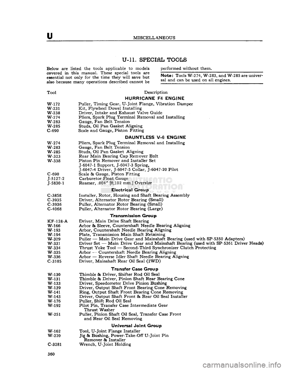
U-ll. SPECIAL TOOLS
Below are listed the
tools
applicable to
models
covered in this manual. These special
tools
are
essential not
only
for the
time
they
will
save
but
also
because
many
operations
described cannot be performed
without
them.
Note;
Tools W-274, W-283, and W-285 are univer
sal
and can be used on all
engines.
Tool
Description
HURRICANE
F4
ENGINE
W-172 Puller, Timing
Gear,
U-Joint Flange, Vibration Damper W-231 Kit, Flywheel Dowel Installing
W-238 Driver, Intake and Exhaust Valve Guide
W-2
74 Pliers, Spark Plug Terminal Removal and Installing W-283 Gauge, Fan Belt Tension W-285 Studs, Oil Pan Gasket Aligning
C-690 Scale and Gauge, Piston Fitting
DAUNTLESS
V-6
ENGINE
W-274 Pliers, Spark Plug Terminal Removal and Installing
W-283 Gauge, Fan Belt Tension W-285 Studs, Oil Pan Gasket Aligning W-323
Rear
Main Bearing Cap Remover Bolt
W-338 Piston Pin Remover and Installer Set
J-6047-1
Support, J-6047-3 Spring,
J-6047-4
Driver, J-6047-5
Collar,
J-6047-20
Pilot
C-690 Scale & Gauge, Piston Fitting
J-5127-2 Carburetor Float Gauge
J-5830-1
Reamer, .004"
[0,102
mm.] Oversize
Electrical
Group
C-3858 Installer, Rotor, Housing and Shaft Bearing Assembly
C-3935 Driver, Alternator Rotor Bearing (Small) C-3936 Puller, Alternator Rotor Bearing (Small)
C-4068 Puller, Alternator Rotor Bearing (Large)
Transmission
Group
KF-128-A
Driver, Main Drive Shaft Bearing W-166 Arbor &
Sleeve,
Countershaft
Needle
Bearing Aligning
W-193 Arbor, Countershaft
Needle
Bearing Aligning W-194 Plate, Transmission Main Shaft Retaining
W-329 Puller — Main Drive
Gear
and Mainshaft Bearing (used with SP-5350 Adapters)
W-331 Driver Set — Main Drive
Gear
and Mainshaft Bearing (used with SP-5361 Driver Heads)
W-334 Thrust Yoke Tool — Second-Third Synchronizer Clutch Protecting W-335 Arbor — Countershaft
Needle
Bearing Aligning
W-336 Arbor — Reverse Idler Shaft
Needle
Bearing Aligning
C-3105 Driver, Mainshaft
Rear
Oil Seal (2WD)
Transfer Case
Group
W-130 Thimble & Driver, Shifter Rod Oil Seal
W-131 Thimble & Driver, Pinion Shaft
Rear
Bearing Cone
W-133 Driver,
Speedometer
Drive Pinion Bushing W-139 Driver, Output Shaft Front Bearing Cone Removing
W-141 Ring, Output Shaft Front Bearing Cone Removing
W-143 Driver, Output Shaft Front &
Rear
Oil Seal Installer W-176 Puller, Shift Rod Oil Seal
W-192 Pilot Pin, Transfer Case Intermediate
Gear
Thrust
Washer
W-251 Puller, Pinion Shaft Oil Seal, Transfer Case Front and
Rear
Oil Seal Removing
Universal
Joint Group
W-162 Tool, U-Joint Flange Installer
W-220 Jig & Bushing, Power-Take-Off U-Joint Pin Remover & Installer
C-3281 Wrench, U-Joint Holding 360
Page 371 of 376
'Jeep'
UNIVERSAL
SERIES SERVICE
MANUAL
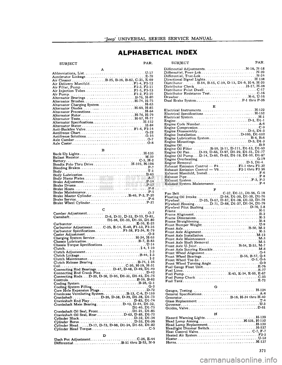
ALPHABETICAL INDEX
SUBJECT PAR.
SUBJECT
PAR.
Abbreviations,
List
U-17 Accelerator Linkage E-70
Air
Cleaner B-25, B-26, B-82, C-21, E-69
Air
Delivery Manifold Fl-4, F2-12
Air
Filter, Pump • F2-3, F2-11
Air
Injection Tubes Fl-5, F2-13
Air
Pump Fl-2, F2-10
Alternator Bearings B-76, H-80
Alternator Brushes H-74, H-75
Alternator Charging System •
•
H-63
Alternator
Diodes
H-69, H-85
Alternator Precautions H-64 Alternator Rotor H-76, H-79
Alternator Tests H-67, H-77 Alternator Specifications H-l 52
Alternator Stator H-84
Anti-Backfire
Valve Fl-6, F2-14
Antifreeze
Chart
• G-22 Antifreeze
Solutions
- G-16
Axle Camber O-l
Axle Caster 0-8
Back-Up
Lights H-135
Ballast
Resistor. H-32 Battery C-3, H-2 Bendix Folo-Thru Drive H-105, H-106
Bleeding Brakes P-7
Body T-l Body Lubrication. B-65 Body Name Plates ' A-7
Brake
Adjustment P-14
Brake
Drums. • .P-17
Brake
Hoses
P-8
Brake
Maintenance . P-5
Brake
Master Cylinder B-40, P-2, P-20
Brake
Service P-6
Brake
Wheel Cylinder • P-21
Camber
Adjustment 0-7
Camshaft D-6, D-51, D-52, D-53, D-81, Dl-26, Dl-33, Dl-55, Dl-80
Carburetor
E-10, E-25
Carburetor
Adjustment C-25, E-14, E-40,
Fl-13,
F2-16
Carburetor
Specifications .Fl-38, F2-34, E-79
Caster
Adjustment 0-8
Charging
System Service. .H-34, H-63
Chassis
Lubrication B-7, B-83
Chassis
Torque Specifications U-14
Clutch
1-4, MO
Clutch
Adjustment 1-3
Clutch
Linkage B-44, 1-3
Clutch
Maintenance .. 1-2
Clutch
Release Bearing B-74, 1-25
Coil
C-20, H-19, H-31 Connecting Rod Bearings D-47, D-48, D-49, Dl-49 Connecting Rod
Crank
Pins D-42
Connecting Rods... .D-20, D-50, D-95, Dl-31, Dl-45, Dl-75
Controls B-59, B-62
Cooling System B-28, G-l Cooling System Filling G-2
Core
Hole Expansion Plugs D-72
Crankcase
Ventilating System B-13, C-6, D-110
Crankshaft
D-26, D-38, D-39, Dl-38, Dl-73
Crankshaft
End Play. D-83, Dl-74
Crankshaft
Main Bearing D-43, D-44, Dl-32, Dl-40, Dl-73
Crankshaft
Oil Seal, Front Dl-21, Dl-85
Crankshaft
Oil Seal, Rear D-63, D-85, Dl-72
Cylinder
Block D-32, Dl-34
Cylinder
Bores D-35, Dl-36
Cylinder
Head D-17, D-73, D-98, Dl-24, Dl-63, Dl-82
Cylinder
Head Torque. C-5
Dash Pot Adjustment C-26, E-44
Differential B-51 thru B-53, N-9 Differential Adjustments N-16, N-18
Differential, Powr-Lok N-20
Differential,
Trac-Lok
N-24
Directional Signal Lights. . H-138
Distributor B-14, B-15, C-10, D-13, Dl-9, H-9, H-20 Distributor Check H-l7, H-28
Distributor Point Dwell C-17 Distributor Resistance Test C-16
Drawbar
.R-6, U-16
Dual
Brake System P-l thru P-26
Electrical
Instruments H-l22
Electrical
Specifications .H-l52
Electrical
System H-l Engine .
..D-l,
Dl-1
Engine Code Number A-6
Engine Compression .
.
C-9 Engine Disassembly . • .D-6, Dl-5 Engine Installation D-105, Dl-102
Engine Lubrication System B-4, B-6 Engine Mountings D-3, Dl-3
Engine Oil B-9
Engine Oil Filter B-10, B-ll,
D-lll,
Dl-13, Dl-93
Engine Oil Pan D-l9, D-66, D-97, Dl-29, Dl-51, Dl-77 Engine Oil Pump. . .D-14, D-65, D-93, Dl-19, Dl-50, Dl-87
Engine Overheating. G-l9 Engine Removal D-5, Dl-4.
Exhaust
Emission Control — F4 Fl-1 thru Fl-30
Exhaust
Emission Control — V6 F2-1 thru F2-36
Exhaust
Manifold, Install F-6
Exhaust
Pipe -
•
F-8
Exhaust
System F-2, F-3
Exhaust
System Maintenance F-4
Fan
Belt C-27, Dl-11, Dl-96, G-18
Floating Oil Intake. D-64, Dl-30, Dl-50, Dl-76 Flywheel D-25, D-67, D-87, Dl-28, Dl-52, Dl-78
Flywheel Housing. D-71, D-88, Dl-27, Dl-54, Dl-79
Flywheel Pilot Bushing D-70, 1-8
Frame
R-l
Frame
Alignment. R-2
Frame
Dimensions R-3
Frame
Straightening R-4
Front
Bumper Weight. • U-9
Front
Axle B-50, M-2
Front
Axle Alignment R-5
Front
Axle Installation • M-12
Front
Axle Maintenance M-3
Front
Axle Shaft Removal M-5
Front
Axle U-Joint B-54, B-55, M-7
Front
Axle Steering Knuckle M-&
Front
Wheel Alignment 0-4
Front
Wheel Bearings B-56, B-57, Q-4
Front
Wheel Toe-in 0-5, 0-6
Front
Wheel Turning Angle 0-9
Fuel
Gauge Float Unit F-76
Fuel
Lines - E-77
Fuel
Pump E-45, E-54, E-60, E-67
Fuel
Pump Check C-23
Fuel
Tank
E-72
G
Gauges, Testing H-l24
General
Specifications A-8
Generator B-16, H-34 thru H-40
Glass
Replacement • T-4
Governor. . .
•.
• U-3
Guides, Valve D"61
H
Hazard
Warning Lights H-139
Head Lamp Aiming H-131, H-132 Head Lamp Replacement H-130
Headlight Dimmer Switch H-l
2
7
Heat Control Valve C-7, F-7 Heated Air System • •
•
F2-2
Heater U-10
Horns.....
....H-137 371