heater JEEP CJ 1953 User Guide
[x] Cancel search | Manufacturer: JEEP, Model Year: 1953, Model line: CJ, Model: JEEP CJ 1953Pages: 376, PDF Size: 19.96 MB
Page 163 of 376

'Jeep*
UNIVERSAL
SERIES SERVICE
MANUAL
G and
scale, especially when used with a flushing
solution. A cleaning solution should be used to
loosen
the rust and scale before reverse flushing
the cooling system.
Flushing
is accomplished through the system in a direction
opposite
to the normal coolant flow.
This
action causes the water to get behind the corrosion
deposits
and force them out. To do this, remove
the upper and lower radiator
hoses.
Then
attach a
drain
hose
at the top of the radiator. Attach a new
piece of
hose
to the radiator
outlet
at the
bottom
and
insert the flushing gun. Connect the water
hose
to the flushing gun to a water
outlet
and the air
hose
to an air line.
Turn
on the water and when
the radiator is
full,
apply the air in short blasts,
allowing the radiator to
fill
between
blasts.
Con
tinue this flushing operation until the water runs
clear
through the top
hose.
With
the thermostat removed, attach a leadaway
hose
to the water
hose
inlet. Also attach a length
of new
hose
to the water
outlet
connection at the
top of the engine.
Turn
the water on and
fill
the
water jacket and then apply air in short blasts.
Continue
this flushing until the water runs clear.
Also
do the hot water heater. Remove heater water
outlet
hose
from heater core. Remove inlet from 163
Page 164 of 376
G
COOLING SYSTEM
engine
connections. Insert flushing gun and flush
heater core.
Care
must be taken when applying air
pressure to prevent damage to the heater core.
G-2.
Filling
Cooling System
To
fill
the cooling system, remove the
fill
cap and
fill
the tank to the top. Replace the cap and run
the
engine
at medium speed for approximately one
minute. Remove the cap and recheck the coolant level. Add more coolant if necessary to bring the level back to the top of the tank. If the cooling system is filled when the
engine
is cold, recheck the coolant level after the
engine
has warmed up.
This
will
ensure that the thermostat has opened allow ing complete cooling system circulation.
Always
correct any cooling system leaks before installing antifreeze. A corrosion inhibitor should be used in the cooling system to prevent the forma
tion of rust and scale. A quality brand antifreeze containing a corrosion inhibitor should be used.
When
the antifreeze is drained in the spring, a
corrosion inhibitor should be added with the water.
Note:
Cooling system components for both V6 and
F4
engines
are shown in
Figs.
G-2 and G-3.
G-3. Draining
Cooling System
To
completely
drain
the cooling system, open the
drain
in the
bottom
of the radiator and also a
drain
on the right side of the cylinder block on the
Hurricane
F4 engine. The Dauntless V-6
engine
has two
drain
plugs, one located on each side of the cylinder block. Both plugs must be removed to
completely
drain
the cooling system.
Remove the radiator cap to break any vacuum
that may have developed.
Should
the cooling solution be lost from the system
and
the
engine
become
overheated do not
refill
the system immediately but allow the
engine
to cool or
refill
slowly while the
engine
is running. If
cold solution is poured into the radiator while the
engine
is overheated there is danger of cracking the
cylinder
block and/or cylinder head.
G-4.
Radiator Pressure
Cap
All
radiators are equipped with pressure caps which
reduce evaporation of cooling solution and make the
engines
more efficient by permitting slightly
higher operating temperatures. When operating
properly,
the pressure cap permits pressure build-up
in
the cooling system during periods of severe heat
load.
This
pressure increases the boiling point of the coolant and thus reduces overflow losses. The
effectiveness
of the cap is limited by its opening
pressure and the boiling point of the coolant (see
note
below). The pressure cap employs a spring-
loaded, rubber-faced pressure seal which presses against a seat in the radiator top tank. Spring pres
sure
determines the opening pressure of the valve.
A
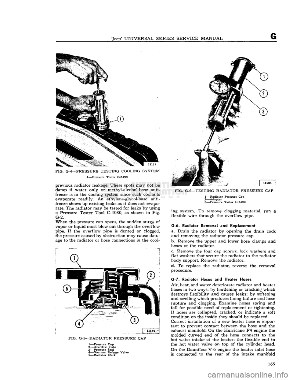
typical pressure cap is shown in Fig. G-5.
Note:
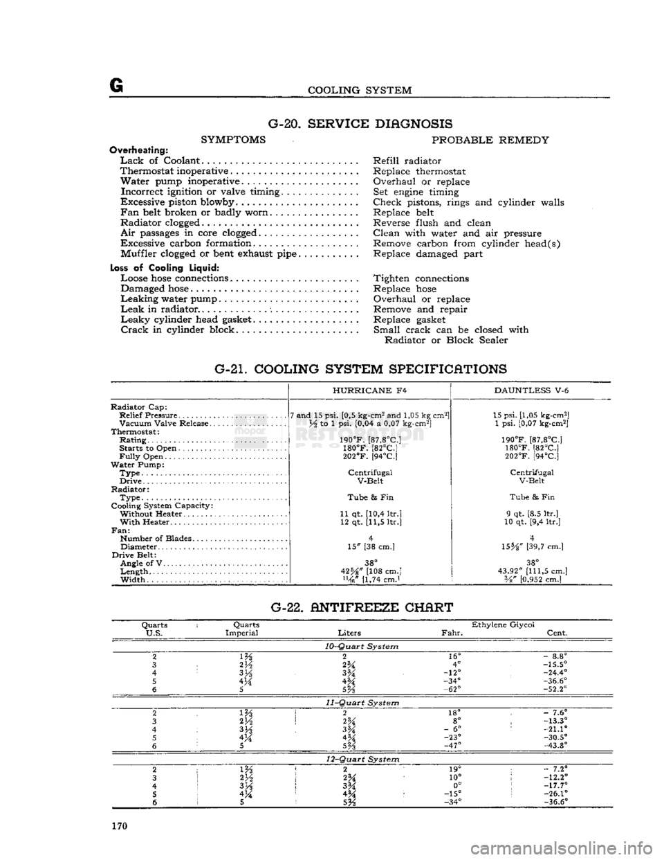
Refer to cooling system specifications (Par.
G-21)
for opening (relief) pressure when the ve
hicle is equipped with either the
Hurricane
F4
or
Dauntless V-6 engine. If a new cap is required, always install a cap of the same type and pressure
rating
specified. It should never be altered or re
placed by a plain cap.
A
vacuum release valve (Fig. G-5) is employed to
prevent undesirable vacuum build-up when the system
cools
down. The vacuum release valve is
held against its seat under light spring pressure.
Vacuum
in the system is relieved by the valve
which
opens
at V2 to 1 psi. [0,035 a 0,07 kg-cm2]
vacuum.
A pressure tester can be used to check and
test
the vacuum pressure rate (see Fig. G-6).
Although the mechanism of the pressure cap re quires no maintenance, the cap should be inspected
periodically for cleanliness and freedom of opera tion. The pressure cap gasket and radiator filler neck seat should also be inspected to be sure they
are
providing a proper seal. If the rubber face of
the valve is defective, a new cap should be installed.
Filler
neck reseating
tools
are commercially
avail
able to correct minor
defects
at the surface of the seat. Follow instructions of the reseating tool manu
facturer.
To
remove the radiator pressure cap when the
engine
coolant temperature is high or boiling, place
a
cloth over the pressure cap and
turn
counter clockwise about Vi
turn
until the first (pressure release)
stop
is reached. Keep the cap in this posi
tion until all pressure is released.
Then
push cap
down and
turn
still
further until cap can be re moved. To install the pressure cap, place it in posi
tion and
turn
it clockwise as far as it
will
go.
Caution:
Use extreme care in removing the radiator
pressure cap. In overheated systems, the sudden release of pressure can cause a steam flash and this
flash,
or the
loosened
cap can cause serious personal
injury.
G-5.
RADIATOR
Maintenance of the radiator consists of keeping
the exterior of the radiator core clean, the interior free from rust and scale, and the radiator free from
leaks.
Check
the cooling system fluid level and for
leaks each
2000
miles
[3.200
km.] or every 30
days, whichever occurs first.
This
exterior of the
radiator
core should be cleaned and the radiator inspected for leaks each
6000
miles
[9.600
km.]
of normal service of the vehicle. Cleaning should be performed by blowing out with air stream or water stream directed from the
rear
of the radiator.
Visual
inspection is not sufficient as the accumula tion of small particles of foreign material on core
surfaces can restrict cooling without closing the core openings.
Radiator
leakage occasionally results from cor
rosion perforation of the metal but most leakage results from mechanical failure of soldered joints
when too much strain has been put on the joint.
Fractures
occur most
often
at the joint where the
radiator
inlet and
outlet
pipes are attached to the
tanks.
When the seams break, the entire soldered
joint
is
exposed
and can corrode, but breakage
rather
than corrosion is the
primary
cause of seam
leakage. Examine the radiator carefully for leaks before and after cleaning. Cleaning may uncover points of leakage already existing but plugged with
rust.
White, rusty, or colored leakage stains indicate 164
Page 165 of 376
'Jeep*
UNIVERSAL SERIES SERVICE
MANUAL
G
FIG.
G-4—PRESSURE TESTING COOLING SYSTEM
1—Pressure Tester C-3499 previous radiator leakage. These
spots
may not be
damp if water only or methyl-alcohol-base anti freeze is in the cooling system since such coolants
evaporate readily. An ethylene-glycol-base anti freeze shows up existing leaks as it
does
not evapo
rate.
The radiator may be tested for leaks by using
a
Pressure Tester Tool C-4080, as shown in Fig.
G-2.
When
the pressure cap opens, the sudden surge of
vapor
or liquid must blow out through the overflow
pipe. If the overflow pipe is dented or clogged,
the pressure caused by obstruction may cause dam
age to the radiator or
hose
connections in the cool-
1
FIG.
G-5—RADIATOR PRESSURE
CAP
1—
Pressure
Cap
2—
Overflow
Tube
3—
Pressure
Seal 4—
Vacuum
Release Valve
5—
Radiator
Neck
FIG.
G-6—TESTING RADIATOR PRESSURE
CAP
1—
Radiator
Pressure Cap
2—
Adapter
3—
Pressure
Tester C-3499 ing system. To remove clogging material, run a
flexible wire through the overflow pipe.
G-6.
Radiator Removal
and
Replacement
a.
Drain
the radiator by opening the
drain
cock
and
removing the radiator pressure cap.
b.
Remove the upper and lower
hose
clamps and
hoses
at the radiator.
c.
Remove the four cap screws, lock washers and
flat washers that secure the radiator to the radiator
body support. Remove the radiator.
d.
To replace the radiator, reverse the removal
procedure.
G-7.
Radiator
Hoses
and
Heater Hoses
Air,
heat, and water deteriorate radiator and heater
hoses
in two ways: by hardening or cracking which
destroys flexibility and causes leaks; by softening
and
swelling which produces lining failure and
hose
rupture
and clogging. Examine
hoses
spring and
fall
for possible need of replacement or tightening.
If
hoses
are collapsed, cracked, or indicate a
soft
condition on the inside they should be replaced.
Correct
installation of a new heater
hose
is impor
tant to prevent contact between the
hose
and the
exhaust manifold. On the
Hurricane
F4 engine the
molded curved end of the
hose
connects to the
hot water intake of the heater; the flexible end to the hot water valve on top of the cylinder head.
On
the Dauntless V-6 engine the heater inlet
hose
is connected to the
rear
of the intake manifold 165
Page 170 of 376
G
COOLING SYSTEM G-20.
SERVICE DIAGNOSIS
SYMPTOMS
PROBABLE REMEDY
Overheating:
Lack
of Coolant Refill radiator
Thermostat inoperative . Replace thermostat
Water
pump inoperative. Overhaul or replace
Incorrect
ignition or valve timing. Set
engine
timing
Excessive piston blowby Check pistons, rings and cylinder walls
Fan
belt
broken or badly worn Replace
belt
Radiator
clogged
Reverse flush and clean
Air
passages
in core
clogged
Clean with water and air pressure
Excessive carbon formation. Remove carbon from cylinder head(s) Muffler
clogged
or
bent
exhaust
pipe
Replace damaged part
Loss
of Cooling
Liquid:
Loose
hose
connections
Tighten
connections
Damaged
hose
Replace
hose
Leaking
water pump Overhaul or replace
Leak
in radiator Remove and repair
Leaky
cylinder head
gasket
Replace
gasket
Crack
in cylinder block. Small crack can be closed with
Radiator
or Block Sealer
G-21. COOLING SYSTEM SPECIFICATIONS
Radiator
Cap:
Relief
Pressure
Vacuum
Valve Release.
Thermostat:
Rating
Starts to Open
Fully
Open
Water
Pump:
Type.
Drive
Radiator:
Type
Cooling System Capacity: Without Heater
With
Heater..
Fan:
Number of Blades Diameter
Drive
Belt: Angle of V
Length
Width
HURRICANE
F4
7 and 15 psi. [0,5 kg-cm2 and 1,05 kg cm2]
lA to 1 psi. [0,04 a 0,07 kg-cm2]
190°F.
[87,8°C]
180°F.
[82°C]
202°F.
[94°C]
Centrifugal
V-Belt
Tube
8s Fin
11 qt. [10,4 ltr.] 12 qt. [11,5 ltr.]
15" [38 cm.]
38°
42%" [108 cm.] [1,74 cmJ
DAUNTLESS
V-6 15 psi. [1,05 kg-cm2]
1 psi. [0,07 kg-cm2]
190°F.
[87,8°C]
180°F.
[82°C]
202°F.
[94°C]
Centrifugal
V-Belt
Tube
& Fin
9 qt. [8.5 ltr.]
10 qt. [9,4 ltr.]
4
\SbA"
[39,7 cm.]
38°
43.92"
[111,5
cm.] Vg"
[0.952
cm.] G-22. ANTIFREEZE CHERT
Quarts
i
Quarts
Ethylene Glycol
U.S.
Imperial
Liters
Fahr.
Cent.
10-Quart
System
2
m
2
16°
-
8.8°
3
2V2
2%
4°
-15.5°
4
3H
-12°
-24.4°
5 4M -34°
-36.6°
6
5
5Vs
-62°
-52.2°
11-Quart
System
2 2
18° -
7.6°
3 2H
2%
8°
-13.3°
4
3%
-
6°
:
-21.10
5 4M 4M -23°
-30.5°
6
5
SVs
-47°
-43.8°
12-Quart
System
2
1 m 2 1
19° ;
- 7.2°
3
2*A
10°
!
-12.2°
4
I
3H
3M 0°
;
-17.7°
5 !
4M 4^ :
-15°
s
-26.1°
6 1 5
5%
-34°
-36.6°
170
Page 174 of 376
H
ELECTRICAL
SYSTEM
the condenser. Replace the condenser. If there is
no jump to full voltage, overhaul or replace the
distributor.
k.
With the points closed, connect the voltmeter
from
a clean, paint-free
post
on the distributor
body to the negative
post
of the battery. The volt
age drop should be practically zero, a hardly
readable deflection on the voltmeter. If the volt meter registers a
voltage
drop, perform the checks
in
steps
1
and m following.
I.
Check
for
voltage
drop in the battery ground
cable.
Clean
the battery
post,
cable terminals, and contact surface on the bellhousing, or on body if
a
noticeable deflection of the voltmeter occurs,
m.
Check
for any
voltage
drop
between
the dis
tributor
body and a clean, paint-free
spot
on the
cylinder
block. If there is any
voltage
drop, remove
the distributor and clean the mounting surfaces of
distributor
body and cylinder block.
H-5.
SECONDARY
CIRCUIT
If
satisfactory ignition is not obtainable with cor
rect
point gap and tension; satisfactory condenser;
sufficient primary voltage; and correctly cleaned, gapped, and installed spark plugs; the secondary
circiut
should be investigated.
a.
Test the coil.
Bring
the coil up to operating
temperature using the coil heat feature of a coil tester, if available. Refer to the coil tester manu
facturer's
instructions for specific hook-ups for
performing the checks given in
steps
b, c, and d following.
b. Connect the positive lead of the tester to the
battery terminal of the coil primary winding.
Con
nect the tester ground lead to the coil tower. Mea
sure
the resistance of the secondary winding. If the
resistance is more than
20,000
ohms, a fault in the
secondary winding is indicated.
c.
Check
for a grounded secondary by touching the tester ground lead to the coil cover. If resistance
is not over
100,000
ohms, the secondary is grounded
to the cover.
d.
If the secondary winding is satisfactory, mea
sure
the primary current draw in accordance with
the instructions of the
test
equipment manu
facturer.
e.
Check
the secondary circuit for leakage. With the coil primary in the circuit with the breaker unit of the tester, connect a long, high-tension
test
lead
to the coil tower.
Check
the secondary circuit for
leakage by performing the checks given in
steps
f. g, h, and i following.
Note:
In the following
tests,
a slight sparking and
meter deflection
will
usually be
seen
just as contact
is made.
This
is caused by capacitance and
does
not
indicate defective insulation.
f.
Check
distributor cap. Remove the coil lead from the cap and touch the
test
lead to the center contact
inside the cap. If the meter reading drops when the contact is touched or if sparking is seen, a leakage
path is present
between
the center contact and one
of the plug towers.
This
leakage path
will
be in the
form
of a
crack
or carbon track in the cap. Discon nect the spark plug wires from the cap one at a
time and
test
each plug contact with the high-
voltage
lead and with all other plug wires con
nected. Any sparking or meter drop indicates that
a
leakage path exists
between
that particular con
tact and an adjacent one. Testing the adjacent contacts
will
determine which pair is at fault,
g-
Check
distributor rotor. Touch the
test
lead to
the spring contact in the center of the distributor
rotor.
Any leakage in the rotor insulation
between
the contact and the shaft
will
cause a drop in the meter reading and usually sparking
will
be seen.
h.
Check
spark plug wires. Disconnect the spark
plug wires from the plugs and
test
the plug terminal of each. The meter reading should not drop below
the open secondary value (value before making contact). If it
does
or if a large spark occurs when
the
test
lead and the plug wire are separated, there
is a break in the insulation on that wire.
i.
Check
the coil tower insulation. Remove the
high-tension
test
lead from the coil tower and touch
the ground lead of the coil tester to several points
around
the base of the tower. Any sparking or deflection of the meter indicates a leakage path in
the tower insulation.
H-6.
Alternator Charging System
All
Jeep
Universal
Series vehicles have, as standard
equipment a 35-amp., 12-volt, negative ground
alternator and a transistorized
voltage
regulator.
For
repairing the alternator, many of its major components are furnished as complete assemblies
including:
complete brush assembly which requires no soldering or unsoldering of leads; two complete
rectifying
diode
assemblies which eliminate the need for removing and replacing individual diodes;
a
complete isolation
diode
assembly; and a rotor assembly complete with shaft,
pole
pieces, field coil,
and
slip rings.
The
transistorized
voltage
regulator is an electronic
switching device. It
senses
the
voltage
appearing at the auxiliary terminal of the alternator and
supplies the necessary field current for maintaining the system
voltage
at the output
terminal.
The out
put current is determined by the battery electrical
load;
such as headlights, heater, etc.
The
transistorized
voltage
regulator is a sealed unit,
has no adjustments, and must be replaced as a
complete unit.
H-7.
Starting System
The
operation of the starter motor is controlled by
the ignition switch. The starter is made up of a
frame,
field coil, armature, and brushes.
The
starter solenoid electrically
closes
the circuit
between
the battery and the starter motor. When the ignition key is turned to its extreme right, the
solenoid is energized and
closes
the battery-to- starter-motor circuit.
Note:
All Jeep Universal Series vehicles have the
starter
solenoid switch secured to the starter motor
assembly. The Hurricane F4 and Dauntless V-6
engine
Prestolite starter drive is of the inertia type
(rexr
continued on
page
176) 174
Page 177 of 376
'Jeep*
UNIVERSAL
SERIES
SERVICE
MANUAL
H
12968
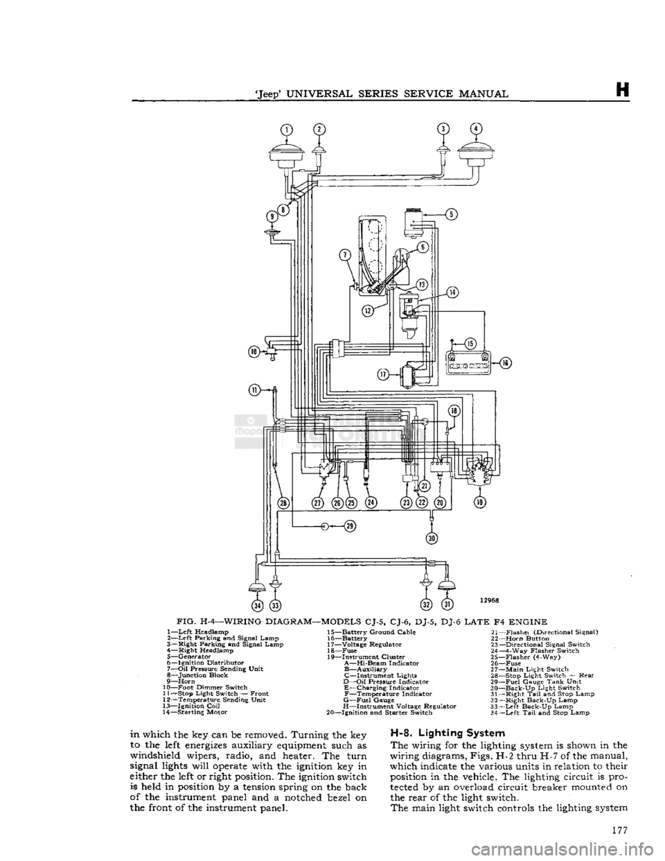
FIG.
H-4—WIRING
DIAGRAM—MODELS
CJ-5, CJ-6, DJ-5, DJ-6
LATE
F4
ENGINE
1—
Left
Headlamp
2—
Left
Parking and Signal Lamp
3— Right Parking and Signal Lamp 4— Right Headlamp
5— Generator
6— Ignition Distributor
7—
Oil
Pressure Sending Unit
8— Junction Block
9—
Horn
10— Foot Dimmer Switch 11—
Stop
Light Switch — Front
12— Temperature Sending Unit
13— Ignition
Coil
14— Starting Motor 15— Battery Ground Cable
16— Battery
17— Voltage Regulator 18—
Fuse
19— Instrument Cluster
A—Hi-Beam
Indicator
B—Auxiliary
C—Instrument
Lights
D—Oil
Pressure Indicator
E—Charging
Indicator
F—Temperature
Indicator
G—Fuel
Gauge
H—Instrument Voltage Regulator
20— Ignition and Starter Switch 21—
Flashei
(Directional Signal)
22—
Horn
Button 23— Directional Signal Switch
24— 4-Way Flasher Switch
25—
Flasher
(4-Way)
26—
Fuse
27—
Main
Light Switch 28—
Stop
Light Switch — Rear
29—
Fuel
Gauge
Tank
Unit
30—
Back-Up
Light Switch
31— Right
Tail
and
Stop
Lamp
32— Right Back-Up Lamp
33—
Left
Back-Up Lamp
34—
Left
Tail
and
Stop
Lamp
in
which the key can be removed. Turning the key
to the
left
energizes
auxiliary
equipment
such as
windshield wipers, radio, and heater. The turn
signal
lights
will
operate
with the
ignition
key in
either the
left
or right
position.
The
ignition
switch is held in
position
by a
tension
spring on the back
of the instrument panel and a
notched
bezel on
the front of the instrument panel.
H-8.
Lighting System
The
wiring for the lighting
system
is shown in the
wiring diagrams, Figs. H-2 thru H-7 of the manual,
which indicate the various units in relation to their
position
in the vehicle. The lighting circuit is pro
tected
by an overload circuit breaker
mounted
on the rear of the light switch.
The
main light switch controls the lighting
system
177
Page 195 of 376
'Jeep*
UNIVERSAL
SERIES SERVICE
MANUAL
H
no soldering or unsoldering of leads; two complete
rectifying
diode assemblies
which
eliminate the need
for removing and replacing individual diodes; a
corpplete isolation diode assembly; and a rotor
assembly complete with shaft,
pole
pieces, field
coil,
and slip rings.
The
transistorized
voltage
regulator is an electronic
switching device. It
senses
the
voltage
appearing
at the auxiliary terminal of the alternator and
supplies the necessary field current for maintaining
the system
voltage
at the output terminal. The
output current is determined by the battery electri
cal
load; such as headlights, heater, etc.
The
transistorized
voltage
regulator is a sealed
unit,
has no adjustments, and must be replaced
as a complete unit.
H-64. ALTERNATOR
PRECAUTIONS
The
following precautions must be observed to
prevent damage to the alternator and regulator.
a.
Never reverse battery connections. Always
check
the battery polarity with a voltmeter before
any
connections are made to be sure that all con
nections correspond to the battery ground polarity of the vehicle.
b.
Booster batteries for starting must be properly
connected. Make sure that the negative cable of
the booster battery is connected to the negative
terminal
of the battery in the vehicle. The positive
cable of the booster battery should be connected
to the positive terminal of the battery in the
vehicle.
c.
Disconnect the battery cables before using a fast charger.
d.
Never use a fast charger as a booster for
starting
the vehicle.
e.
Never disconnect the
voltage
regulator while
the
engine
is running.
f.
Do not ground the alternator output terminal.
g.
Do not operate the alternator on an open
circuit
with
the field energized.
h.
Do not attempt to polarize an alternator.
These
precautions are stated here as an aid to
service
personnel. They are also restated at appro
priate
places in the
text
of this section of the
manual.
H-65. ALTERNATOR
CHARGING
SYSTEM SERVICE
Important:
All alternator
tests
for the 35, 40 and
55 amp alternator are the same, however, there is a
difference
between
the location of the various ter
minals
and field current specifications. The field
current
of the 35 amp alternator should be 1.7 to 2.3 amps, 40 and 55 amp alternators should be 1.8
to 2.4 amps, with
full
battery
voltage
applied to
the filed coil. Disassembly and assembly procedures
are
the same for all three alternators.
Terminal
locations and wire harness color
codes
for the 35,
40 and 55 amp alternator are shown in Fig. H-38.
H-66.
Service Diagnosis
In
diagnosing a suspected malfunction of the
alternator
charging system, consideration must
be given to the complete electrical power plant of the vehicle; including the alternator, regulator,
ignition switch, charge indicator lamp, battery,
and
all associated wiring. If it is suspected that the
alternator
is not fully charging the battery and
fulfilling
the electrical requirements of the electrical
system, several checks should be made before
checking
the alternator itself:
Note:
Whenever service is required in connection
with
an alternator problem, the first
step
should be to verify that the wiring harness hook-up is correct
as indicated in Fig. H-38.
a.
Test the condition of the battery and
state
of
charge
(Par. H-2).
If the battery is not fully charged
and
in
good
condition, use a replacement battery
for making alternator system
tests.
Caution:
Make certain that the negative battery
post
is connected to ground when making the
battery installation. Serious damage to the alter
nator
can result if battery polarity is reversed.
b.
Check
fan belt for proper tension (Par.
C-27).
Caution:
To increase belt tension, apply pressure
to alternator front housing only as permanent damage can result if pressure is applied to
rear
housing.
H-67.
Alternator In Vehicle Tests
The
following
tests
are made with the alternator
in
the vehicle with output and regulator connec
tions maintained to the alternator except as noted
in
Fig. H-27 and H-28. The field plug and
voltage
regulator are disconnected for
these
tests.
The
tests
are given in proper order and detail in the
following paragraphs.
a.
Isolation Diode Test: To determine if the isola
tion diode is open or shorted, refer to Par. H-69.
b.
Alternator Output Test: To isolate the trouble
to the alternator or regulator, refer to Par. H-70.
c.
Alternator
Field
Circuit
Test: To determine the condition of the field
circuit
(brushes and rotor),
refer
to Par. H-73.
d.
Brush
Insulation
and Continuity
Test:
To deter
mine the condition of the
brush,
refer to
Par.
H-75.
e.
Rotor In-Vehicle Test: To determine whether
the rotor coil is open or shorted, refer to
Par.
H-73.
f. Any further
tests
must be conducted with the
alternator
removed and disassembled. When this
is done, the condition of the rotor, the rectifying
and
isolation diodes, and the stator can be further
tested.
A
commercial alternator tester Sun
Electric
Model
VAT-20
or equivalent can be used to make all
necessary
tests
on the alternator system. If a com
mercial
tester is used, follow the recommended
testing procedure outlined by the tester manu
facturer.
If
a commercial tester is not available, follow the
testing procedure as outlined in this manual.
H-68.
Test Equipment
a.
Volt Ampere Tester such as Sun
Electric
Model
VAT-20
or equivalent with meter ranges as shown
in
the following list can be used. 195
Page 224 of 376
H
ELECTRICAL
SYSTEM
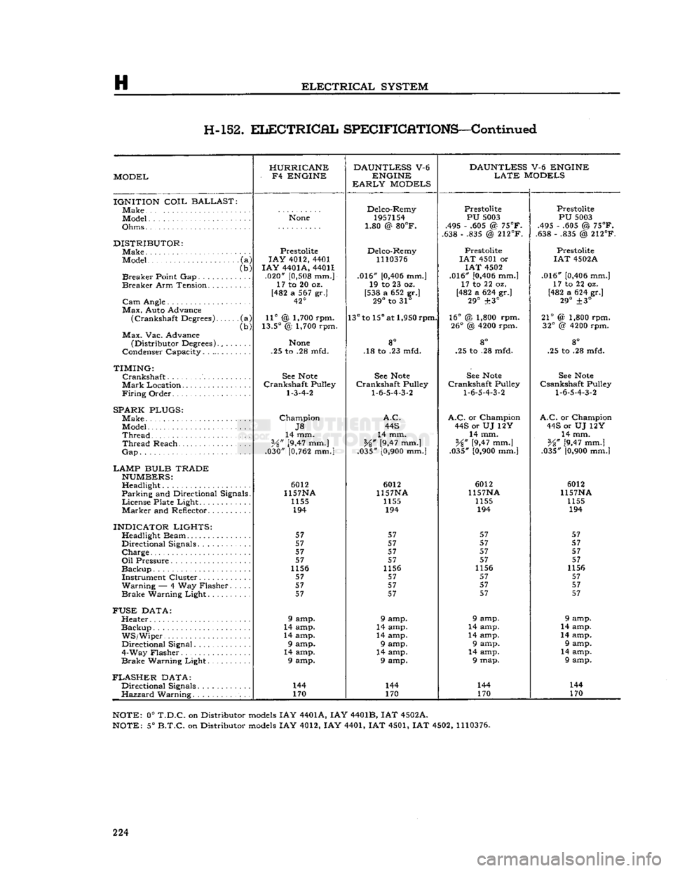
H-152.
ELECTRICAL
SPECIFICATIONS—Continued
HURRICANE DAUNTLESS
V-6
DAUNTLESS
V-6 ENGINE
MODEL -
F4
ENGINE
ENGINE
LATE
MODELS
EARLY
MODELS
IGNITION
COIL
BALLAST
]Make Delco-Remy
Prestolite Prestolite
Model
None
1957154
PU
5003
PU
5003
Ohms • • 1.80 @
80°F.
.495 - .605 @
75°F.
.495 - .605 @
75°F.
1.80 @
80°F.
.638 - .835 @
212°F.
.638 - .835 @
212°F.
DISTRIBUTOR:
Prestolite Delco-Remy Prestolite Prestolite
Model
•
(a)
LAY
4012, 4401
1110376
I
AT
4501 or
IAT
4502A
(b)
I
AY
4401A, 44011
IAT
4502
Breaker
Point Gap (b)
.020"
[0,508
mm.] .016"
[0,406
mm.] .016"
[0,406
mm.]
.016"
[0,406
mm.]
Breaker
Arm Tension. ..... 17 to 20 oz.
19 to 23 oz. 17 to 22 oz. 17 to 22 oz.
[482 a 567 gr.] [538 a 652 gr.] [482 a 624 gr.]
[482 a 624 gr.]
42° 29°
to 31°
29°
±3°
29°
±3°
Max.
Auto Advance
(Crankshaft
Degrees) •(a)
11°
@ 1,700 rpm.
13°
to
15°
at 1,950 rpm.
16°
@ 1,800 rpm.
21°
(2 1,800 rpm.
(Crankshaft
Degrees)
(b)
13.5°
@ 1,700 rpm.
26°
@
4200
rpm.
32°
@
4200
rpm.
Max.
Vac. Advance go
(Distributor Degrees)., . .
None
8° 8°
go
Condenser Capacity. . .25 to .28 mfd. .18 to .23 mfd. .25 to .28 mfd. .25 to .28 mfd.
TIMING:
Crankshaft
See
Note
See
Note
See
Note
See
Note
Mark
Location............
Crankshaft
Pulley
Crankshaft
Pulley
Crankshaft
Pulley
Csankshaft
Pulley
Firing
Order
1-3-4-2
1-6-5-4-3-2
1-6-5-4-3-2 1-6-5-4-3-2
SPARK PLUGS:
Make
Champion
A.C. A.C.
or Champion
A.C.
or Champion
J8
44S
44S or UJ 12Y 44S or UJ 12Y
Thread
14 mm.
14 mm. 14 mm. 14 mm.
Thread
Reach
Vz"
[9,47 mm.]
%"
[9,47 mm.]
¥%"
[9,47 mm.]
V8" [9,47 mm.]
Gap
.030"
[0,762
mm.]
.035"
[0,900
mm.] .035"
[0,900
mm.] .035"
[0,900
mm.|
LAMP BULB TRADE
NUMBERS:
Headlight 6012
6012 6012 6012
Parking
and Directional Signals. 1157NA
1157NA 1157NA 1157NA
License
Plate Light........ 1155
1155 1155 1155
Marker
and Reflector 194
194 194 194
INDICATOR LIGHTS:
57 57 57 57
Directional Signals........ 57
57 57 57
Charge
57
57 57 57
57 57 57 57
1156 1156 1156 1156
Instrument Cluster 57 57 57 57
Warning
— 4 Way Flasher. . 57
57 57 57
Brake
Warning Light 57
57 57 57
FUSE
DATA:
Heater 9 amp. 9 amp. 9 amp. 9 amp.
Backup
14 amp. 14 amp. 14 amp. 14 amp.
WS/Wiper.
14 amp. 14 amp. 14 amp. 14 amp.
Directional Signal 9 amp. 9 amp. 9 amp. 9 amp.
4-Way Flasher 14 amp. 14 amp. 14 amp. 14 amp.
Brake
Warning Light 9 amp. 9 amp. 9 map. 9 amp.
FLASHER
DATA:
Directional Signals. 144
144 144 144
Hazzard
Warning. 170
170 170 170
NOTE:
0°
T.D.C.
on Distributor
models
IAY 4401A, IAY 4401B, IAT 4502A.
NOTE:
5°
B.T.C.
on Distributor
models
IAY 4012, IAY 4401, IAT 4501, IAT 4502,
1110376.
224
Page 354 of 376
T
BODY
from the windshield wiper vacuum fitting. On
late
models
disconnect electrical wires from wiper
motor. Unlatch the two windshield clamps on each
side
of the windshield.
Fold
the windshield forward
until
the
slot
in the windshield
hinges
aligns with the flat
side
of the pin in the
body
hinges.
Slip wind
shield off the pins and remove from
body.
T-4.
Windshield Glass
The
windshield
glass
is mounted in a rubber
weatherstrip which in turn
mounts
in the frame. A
rubber
locking strip, which
holds
the
glass
firmly in
the frame, is inserted in a moulded
groove
around
the rear
face
of the weatherstrip as shown in Fig.
T-2.
To remove the
glass
it is necessary to first
remove the locking strip which may be pried out
with a screwdriver or similar
tool.
Installation is,
obvious.
T-5.
Canvas Tops
Canvas
tops
are available in
Half
Tops and
Full
Tops.
Installation instructions are provided with
each canvas top kit for each model vehicle.
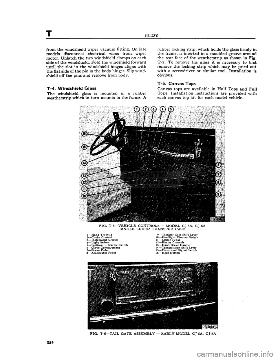
FIG.
T-5—VEHICLE CONTROLS — MODEL CJ-5A, CJ-6A
SINGLE
LEVER
TRANSFER CASE 1—
Hand
Throttle 9—Transfer Case Shift
Lever
2—
Choke
Control 10—Headlight Dimmer Switch
3— Instrument Cluster 11—Clutch Pedal 4—
Light
Switch 12—Heater Controls 5— Ignition — Starter Switch 13—Hand
Brake
Handle
6— Glove Compartment 14—Transmission Shift
Lever
7—
Brake
Pedal 15—Directional Signal Switch
8— Accelerator Pedal 16—Horn Button
FIG.
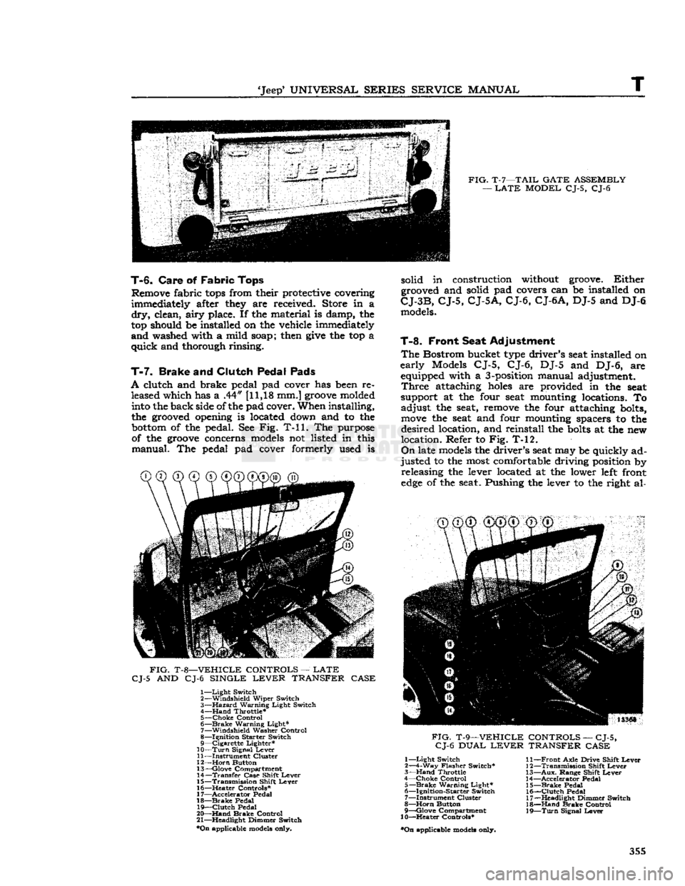
T-6—TAIL GATE ASSEMBLY —
EARLY
MODEL CJ-5A, CJ-6A
354
Page 355 of 376
'Jeep'
UNIVERSAL
SERIES
SERVICE
MANUAL
T
FIG.
T-7—TAIL
GATE
ASSEMBLY
—
LATE
MODEL
CJ-5, CJ-6
T-6.
Care
of
Fabric
Tops
Remove fabric
tops
from their protective covering
immediately after they are received. Store in a
dry,
clean,
airy
place. If the material is damp, the
top should be installed on the vehicle immediately
and
washed with a mild soap; then
give
the top a
quick
and thorough rinsing.
T-7.
Brake
and
Clutch Pedal Pads
A
clutch and brake pedal pad cover has been re leased which has a .44" [11,18 mm.]
groove
molded into the back side of the pad cover. When installing,
the grooved opening is located down and to the
bottom
of the pedal. See Fig. T-ll. The purpose of the
groove
concerns models not listed in this
manual.
The pedal pad cover formerly used is
FIG.
T-8—VEHICLE
CONTROLS
—
LATE
CJ-5
AND CJ-6
SINGLE
LEVER
TRANSFER
CASE
1—
Light
Switch
2—
Windshield
Wiper
Switch
3—
Hazard
Warning
Light
Switch
4—
Hand
Throttle*
5—
Choke
Control
6—
Brake
Warning
Light*
7—
Windshield
Washer
Control
8—
Ignition
Starter
Switch
9—
Cigarette
Lighter*
10—
Turn
Signal
Lever
11—
Instrument
Cluster
12—
Horn
Button
13—
Glove
Compartment
14—
Transfer
Case
Shift
Lever
15—
Transmission
Shift
Lever
16—
^Heater
Controls*
17—
Accelerator
Pedal
18—
Brake
Pedal
19—
Clutch
Pedal
20—
Hand
Brake
Control
21—
Headlight
Dimmer
Switch
*On
applicable models only. solid in construction without groove.
Either
grooved and solid pad covers can be installed on
CJ-3B,
CJ-5,
CJ-5A,
CJ-6,
CJ-6A,
DJ-5 and DJ-6 models.
T-8.
Front Seat Adjustment
The
Bostrom bucket type driver's seat installed on
early
Models CJ-5, CJ-6, DJ-5 and DJ-6, are equipped with a 3-position manual adjustment.
Three
attaching
holes
are provided in the seat
support at the four seat mounting locations. To
adjust
the seat, remove the four attaching bolts,
move
the seat and four mounting spacers to the
desired
location, and reinstall the
bolts
at the new
location. Refer to Fig. T-12.
On
late models the driver's seat may be quickly ad
justed
to the most comfortable driving position by releasing the lever located at the lower left front
edge
of the seat. Pushing the lever to the right al-
CD CD®
®@©"®^
FIG.
T-9—VEHICLE
CONTROLS
—
CJ-5,
CJ-6
DUAL
LEVER
TRANSFER
CASE
1—
Light
Switch
2—4-Way
Flasher
Switch*
3—
Hand
Throttle
4—
Choke
Control
5—
Brake
Warning
Light*
6—
Ignition-Starter
Switch
7—
Instrument
Cluster
8—
Horn
Button
9—
Qlove
Compartment
10—Heater
Controls*
•On
applicable models only.
11—
Front
Axle
Drive
Shift
Lever
12—
Transmission
Shift
Lever
13—
Aux.
Range
Shift
Lever
14—
Accelerator
Pedal
15—
Brake
Pedal
16—
Clutch
Pedal
17—
Headlight
Dimmer
Switch
18—
Hand
Brake
Control
19—
Turn
Signal
Lever
355