low beam JEEP CJ 1953 User Guide
[x] Cancel search | Manufacturer: JEEP, Model Year: 1953, Model line: CJ, Model: JEEP CJ 1953Pages: 376, PDF Size: 19.96 MB
Page 282 of 376

FRONT
AXLE
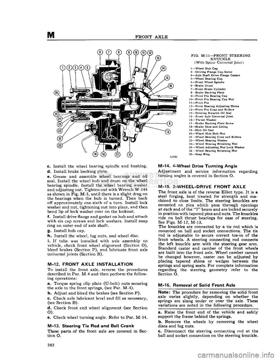
FIG.
M-l
1—FRONT
STEERING
KNUCKLE
(With
Spicer Universal Joint)
1—
Wheel
Hub Cap
2—
Driving
Flange Cap Screw
3—
Axle
Shaft Drive Flange Gasket 4—
Wheel
Bearing Cup
5—
Front
Wheel Spindle
6—
Brake
Drum
7—
Front
Brake
Cylinder
8—
Brake
Backing Plate
9—
Pivot
Pin Bearing Cap
10—
Pivot
Pin Bearing Cap Nut
11—
Pivot
Pin 12—
Pivot
Bearing Adjusting Shims
13—
Pivot
Pin Cone and Rollers
14—
Steering
Knuckle
Oil Seal 15—
Front
Axle Universal Joint
16—
Thrust
Washer
17—
Brake
Backing Plate Screw
18—
Brake
Shoe and
Lining
19—
Hub
Oil Seal
20—
Wheel
Hub Bolt Nut
21—
Wheel
Bearing Cone and Rollers 22—
Wheel
Bearing Washer
23—
Wheel
Bearing Retaining Nut
24—
Wheel
Adjusting Nut
Lock
Washer
25—
Wheel
Bearing Retaining Nut
26—
Snap
Ring
c.
Install
the wheel bearing spindle and bushing.
d.
Install
brake backing plate.
e.
Grease and assemble wheel bearings and oil
seal.
Install
the wheel hub and drum on the wheel
bearing
spindle.
Install
the wheel bearing washer
and
adjusting nut. Tighten nut with
Wrench
W-144
as shown in
Fig.
M-5, until there is a slight drag on the bearings when the hub is turned.
Then
back off approximately one-sixth of a
turn.
Install
lock
washer
and nut, tightening nut
into
place, and then bend lip of lock washer over on the locknut.
f.
Install
drive
flange
and gasket on hub and attach
with
six cap screws and lock washers.
Install
snap
ring
on outer end of axle shaft.
g.
Install
hub cap.
h.
Install
the wheel, lug nuts, and wheel disc.
i.
If
tube
was installed with axle assembly on
vehicle, check front wheel alignment (Section O),
bleed brakes (Section P), and lubricate front axle
universal
joints (Section B).
M-12.
FRONT
AXLE
INSTALLATION
To
install the front axle, reverse the procedures described in
Par.
M-4 and then perform the follow
ing operations:
a.
Torque spring clip plate (U-bolt) nuts securing the axle to the front springs, (see Par. M-4).
b.
Adjust and bleed the brakes (see Section P).
c.
Check
axle lubricant level and
fill
as necessary, (see Section B).
d.
Check
front end wheel alignment (see Section
O).
e.
Check
wheel turning angle. Refer to Par. M-14.
M-13.
Steering
Tie Rod and
Bell Crank
These
parts of the front axle are covered in Sec
tion O.
M-14.
4-Wheel Drive
Turning
Angle
Adjustment
and service information regarding
turning
angles
is covered in Section O.
M-15.
2-WHEEL-DRIVE
FRONT
AXLE
The
front axle is of the reverse
Elliot
type. It is a
steel forging, heat treated for strength and ma
chined
to
close
limits. The steering knuckles are
mounted on pins which pass through
openings
at each end of the
"I"
beam and are locked securely
in
position with tapered pins and nuts. The knuckles
ride
on
ball
thrust bearings for
ease
of steering. See
Figs.
M-12, M-13.
The
knuckles are connected by a tie rod which is
mounted on
ball
and socket connections. The tie
rod
is adjustable to secure correct
toe-in
of the front wheels. A steering connecting rod
connects
the
left
knuckle arm with the steering gear arm.
Standard
caster and camber of the front
wheels
are
built
into
the front axle. Wheel camber cannot
be changed however, caster can be adjusted by
placing
tapered shims or
wedges
between
the
springs and spring seats. For
complete
information
regarding
the steering
geometry
refer to the
Section O.
M-16.
Removal of Solid
Front
Axle
Note:
The procedure for removing the solid front
axle varies slightly, depending on whether the
springs are slung under or over the axle. These
variations
are
noted
in the following procedure.
a. -
Raise the front end of the vehicle and safely support the frame behind the springs.
b.
Remove the
wheels
by removing the wheel
discs and lug nuts.
c.
Disconnect the steering connecting rod at the
ball
and socket connection on the steering knuckle. 282
Page 345 of 376

'Jeep'
UNIVERSAL
SERIES
SERVICE
MANUAL
s
SPRINGS
AND
SHOCK
ABSORBERS
Contents
SUBJECT
PAR. SUBJECT PAR.
Pivot Bolts S-3 Spring Removal S-4
Shock
Absorbers S-7 Spring Shackles S-2
Spring
Installation S-5 U-Shackles S-6
S-1.
GENERAL
Semielliptical
leaf springs are used for all models.
The
springs are hung longitudinally from the frame
side rails by means of brackets welded to the
rails.
All
axles are firmly attached to the springs by U-
bolts
(spring clips), spring saddles welded to the
underside of the axles, and spring plates under the
springs.
Early
model DJ-5 and DJ-6 front axles (I beam) are attached to the springs with conven
tional
bolts
and spring plates. Spring center
bolts
are
inserted in the axle spring saddles to prevent
shifting of the axle.
All
front springs, except as noted below, are provided with shackles at the front ends of the springs
and
pivot
bolts
at the
rear
ends of the springs. Model CJ-5 up to
Serial
No. 44437 and Model
CJ-6
up to
Serial
No. 11981 are provided with shackles at the
rear
ends of the front springs, and
pivot
bolts
at the front ends.
Note:
Models
CJ-5A
and
CJ-6A
are equipped with
the two
stage
type front and
rear
spring.
All
rear
springs are provided with shackles at the
rear
end and pivot
bolts
at the front end.
Springs
should be examined periodically for broken
or
shifted leaves,
loose
or missing rebound clips,
angle of spring shackles, and position of springs
on the saddles. Springs with shifted leaves do not have their normal strength. Missing rebound clips may permit the spring leaves to fan out or break
on rebound. Broken leaves may make the vehicle
hard
to handle or permit the axle to shift out of
line.
Weakened springs may break causing difficulty
in
steering. Spring attaching clips or
bolts
must be tight. It is
suggested
that they be checked at each
vehicle inspection and torqued 45 to 55 lb-ft. [6,2 a 7,6 kg-m.].
S-2.
Spring Shackles
Rubber-bushed
shackles are provided on all current
production vehicles. The steel-backed rubber (silent bloc) bushings are pressed into the spring
eyes
and mounting brackets. The shackle
bolts
tighten the side plates against the inner steel back
ing of the bushings. Oscillation of the springs is
taken in the rubber bushings.
All
vehicles produced before early 1957 were
equipped with U-shackles and threaded core bush-
*3(
21-
to It is
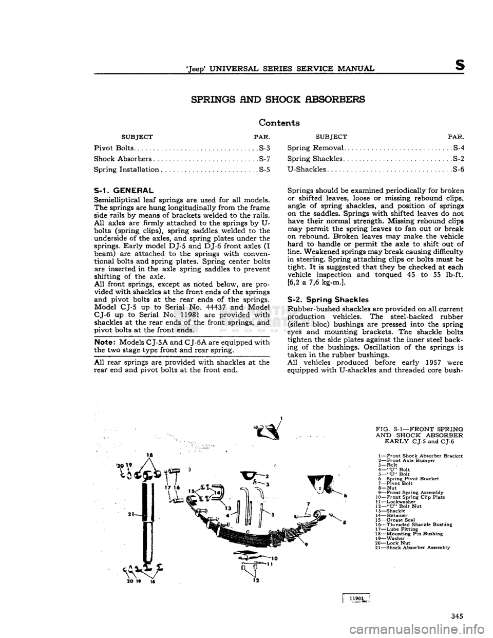
FIG-
S-1—FRONT SPRING
AND SHOCK ABSORBER
EARLY
CJ-5 and CJ-6
1—
Front
Shock Absorber
Bracket
2—
Front
Axle
Bumper
3—
Bolt
4—
"U"
Bolt
5—
"U"
Bolt
6—
Spring
Pivot
Bracket
7—
Pivot
Bolt
8—
Nut
9—
Front
Spring
Assembly
10—Front
Spring
Clip
Plate
11
—Lockwasher
12—
"U"
Bolt Nut
13—
Shackle
14—
Retainer
15—
Grease
Seal
16—
Threaded
Shackle
Bushing
17—
Lube
Fitting
18—
Mounting
Pin Bushing
19—
Washer
20—
Lock
Nut
21—
Shock
Absorber Assembly
1190L
345