jump start JEEP CJ 1953 Service Manual
[x] Cancel search | Manufacturer: JEEP, Model Year: 1953, Model line: CJ, Model: JEEP CJ 1953Pages: 376, PDF Size: 19.96 MB
Page 29 of 376
'Jeep'
UNIVERSAL
SERIES
SERVICE
MANUAL
C
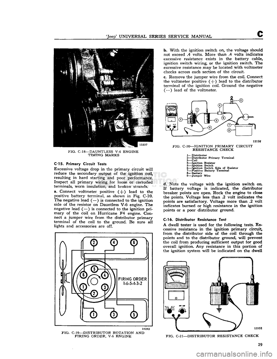
FIG.
C-18—DAUNTLESS
V-6
ENGINE
TIMING
MARKS
C-15.
Primary
Circuit
Tests
Excessive
voltage
drop in the primary circuit
will
reduce the secondary output of the ignition coil,
resulting in hard starting and poor performance. Inspect all primary wiring for
loose
or corroded
terminals, worn insulation, and broken strands,
a.
Connect voltmeter positive (-J-) lead to the
positive battery terminal, as shown in Fig. C-20.
The
negative
lead (—) is connected to the ignition
side of the resistor on Dauntless V-6
engine.
The
negative
lead (—) is connected to the ignition
pri
mary
of the coil on Hurricane F4
engine.
Con
nect a jumper wire from the distributor primary
terminal
of the coil to the ground. Be sure all lights and accessories are off. b. With the ignition switch on, the
voltage
should
not
exceed
.4 volts. More than .4
volts
indicates
excessive
resistance
exists
in the battery cable, ignition switch wiring, or the ignition switch. The
excessive
resistance may be located with voltmeter checks across each section of the circuit.
c. Remove the jumper wire from the coil. Connect
the voltmeter positive (-f) lead to the distributor
terminal
of the ignition coil. Ground the
negative
(—) lead of the voltmeter.
12156
FIG.
C-20—IGNITION
PRIMARY
CIRCUIT
RESISTANCE
CHECK
1—
Distributor
2—
Distributor
Primary
Terminal
3—
Coil
4— Ignition Resistor 5— Ignition Switch 6— Ignition Switch Side of Resistor 7— Positive Battery
Terminal
8—
Battery
9—
Jumper
Wire
d.
Note
the
voltage
with the ignition switch on.
If
battery
voltage
is indicated, the distributor
breaker
points
are open. Rock the
engine
to
close
the points. Voltage
less
than .2 volt indicates the
points
are satisfactory. Voltage more than .2 volt indicates burned or high resistance in the ignition
points
or a poor distributor ground.
C-l
6. Distributor
Resistance
Test
A
dwell tester is used for the following
tests.
Ex
cessive resistance in the ignition primary circuit,
from the distributor side of the coil through the
points
and to the distributor ground,
will
prevent
the coil from producing sufficient output for
good
overall
ignition. Any resistance in this portion of
the ignition system
will
be indicated on the dwell
FIG.
C-21—DISTRIBUTOR
RESISTANCE
CHECK
14242
FIG.
C-19—DISTRIBUTOR
ROTATION
AND
FIRING
ORDER,
V-6
ENGINE
29
Page 173 of 376
'Jeep'
UNIVERSAL
SERIES
SERVICE
MANUAL
H
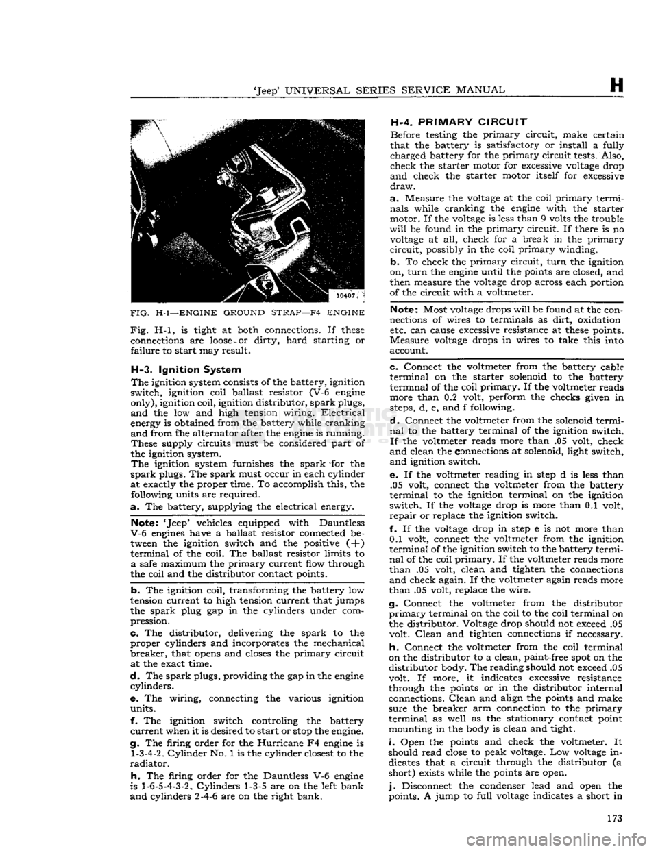
FIG.
H-l—ENGINE
GROUND
STRAP—F4
ENGINE
Fig.
H-l, is tight at both connections. If
these
connections are
loose
-
or
dirty,
hard
starting or
failure
to start may result.
H-3.
Ignition System
The
ignition system consists of the battery, ignition
switch,
ignition coil ballast resistor (V-6 engine
only),
ignition coil, ignition distributor,
spark
plugs,
and
the low and high tension wiring.
Electrical
energy is obtained from the battery while cranking
and
from the alternator after the engine is running.
These
supply circuits must be considered part of
the ignition system.
The
ignition system furnishes the
spark
-for the
spark
plugs. The
spark
must occur in each cylinder
at exactly the proper time. To accomplish this, the following units are required.
a.
The battery, supplying the electrical energy.
Note: 'Jeep* vehicles equipped with Dauntless
V-6
engines have a ballast resistor connected be tween the ignition switch and the positive (+)
terminal
of the coil. The ballast resistor limits to
a
safe maximum the
primary
current flow through
the coil and the distributor contact points.
b.
The ignition coil, transforming the battery low
tension current to high tension current that jumps
the
spark
plug gap in the cylinders under com
pression.
c.
The distributor, delivering the
spark
to the
proper
cylinders and incorporates the mechanical
breaker,
that
opens
and closes the
primary
circuit at the exact time.
d.
The
spark
plugs, providing the gap in the engine
cylinders.
e. The wiring, connecting the various ignition
units.
f. The ignition switch controling the battery
current
when it is desired to start or
stop
the engine.
g. The firing order for the
Hurricane
F4 engine is
1-3-4-2.
Cylinder
No. 1 is the cylinder closest to the
radiator.
h.
The firing order for the Dauntless V-6 engine
is
1-6-5-4-3-2.
Cylinders
1-3-5 are on the left bank
and
cylinders 2-4-6 are on the right bank. H-4.
PRIMARY
CIRCUIT
Before testing the
primary
circuit,
make certain
that the battery is satisfactory or install a fully
charged
battery for the
primary
circuit
tests. Also,
check
the starter motor for excessive voltage drop
and
check the starter motor itself for excessive
draw.
a.
Measure the voltage at the coil
primary
termi
nals
while cranking the engine with the starter
motor. If the voltage is less than 9 volts the trouble
will
be found in the
primary
circuit.
If there is no voltage at all, check for a break in the
primary
circuit,
possibly in the coil
primary
winding.
b.
To check the
primary
circuit,
turn
the ignition
on,
turn
the engine until the points are closed, and
then measure the voltage drop across each portion
of the circuit with a voltmeter.
Note: Most voltage drops
will
be found at the con
nections of wires to terminals as
dirt,
oxidation etc. can cause excessive resistance at
these
points.
Measure
voltage drops in wires to take this into
account.
c.
Connect the voltmeter from the battery cable
terminal
on the starter solenoid to the battery
terminal
of the coil
primary.
If the voltmeter reads more than 0.2 volt, perform the checks given in
steps, d, e, and f following.
d.
Connect the voltmeter from the solenoid termi
nal
to the battery terminal of the ignition switch.
If
the voltmeter reads more than .05 volt, check
and
clean the connections at solenoid, light switch,
and
ignition switch.
e. If the voltmeter reading in
step
d is less than .05 volt, connect the voltmeter from the battery
terminal
to the ignition terminal on the ignition
switch.
If the voltage drop is more than 0.1 volt,
repair
or replace the ignition switch.
f. If the voltage drop in
step
e is not more than 0.1 volt, connect the voltmeter from the ignition
terminal
of the ignition switch to the battery termi
nal
of the coil
primary.
If the voltmeter reads more
than
.05 volt, clean and tighten the connections
and
check again. If the voltmeter again reads more
than
.05 volt, replace the wire.
g. Connect the voltmeter from the distributor
primary
terminal on the coil to the coil terminal on
the distributor. Voltage drop should not exceed .05 volt.
Clean
and tighten connections if necessary.
h.
Connect the voltmeter from the coil terminal
on the distributor to a clean,
paint-
free spot on the
distributor
body. The reading should not exceed .05
volt. If more, it indicates excessive resistance
through the points or in the distributor internal connections.
Clean
and align the points and make
sure
the breaker arm connection to the
primary
terminal
as well as the stationary contact point mounting in the body is clean and tight.
i.
Open the points and check the voltmeter. It
should read close to peak voltage. Low voltage in dicates that a circuit through the distributor (a
short)
exists while the points are open.
j.
Disconnect the condenser lead and open the points. A jump to
full
voltage indicates a short in 173
Page 174 of 376
H
ELECTRICAL
SYSTEM
the condenser. Replace the condenser. If there is
no jump to full voltage, overhaul or replace the
distributor.
k.
With the points closed, connect the voltmeter
from
a clean, paint-free
post
on the distributor
body to the negative
post
of the battery. The volt
age drop should be practically zero, a hardly
readable deflection on the voltmeter. If the volt meter registers a
voltage
drop, perform the checks
in
steps
1
and m following.
I.
Check
for
voltage
drop in the battery ground
cable.
Clean
the battery
post,
cable terminals, and contact surface on the bellhousing, or on body if
a
noticeable deflection of the voltmeter occurs,
m.
Check
for any
voltage
drop
between
the dis
tributor
body and a clean, paint-free
spot
on the
cylinder
block. If there is any
voltage
drop, remove
the distributor and clean the mounting surfaces of
distributor
body and cylinder block.
H-5.
SECONDARY
CIRCUIT
If
satisfactory ignition is not obtainable with cor
rect
point gap and tension; satisfactory condenser;
sufficient primary voltage; and correctly cleaned, gapped, and installed spark plugs; the secondary
circiut
should be investigated.
a.
Test the coil.
Bring
the coil up to operating
temperature using the coil heat feature of a coil tester, if available. Refer to the coil tester manu
facturer's
instructions for specific hook-ups for
performing the checks given in
steps
b, c, and d following.
b. Connect the positive lead of the tester to the
battery terminal of the coil primary winding.
Con
nect the tester ground lead to the coil tower. Mea
sure
the resistance of the secondary winding. If the
resistance is more than
20,000
ohms, a fault in the
secondary winding is indicated.
c.
Check
for a grounded secondary by touching the tester ground lead to the coil cover. If resistance
is not over
100,000
ohms, the secondary is grounded
to the cover.
d.
If the secondary winding is satisfactory, mea
sure
the primary current draw in accordance with
the instructions of the
test
equipment manu
facturer.
e.
Check
the secondary circuit for leakage. With the coil primary in the circuit with the breaker unit of the tester, connect a long, high-tension
test
lead
to the coil tower.
Check
the secondary circuit for
leakage by performing the checks given in
steps
f. g, h, and i following.
Note:
In the following
tests,
a slight sparking and
meter deflection
will
usually be
seen
just as contact
is made.
This
is caused by capacitance and
does
not
indicate defective insulation.
f.
Check
distributor cap. Remove the coil lead from the cap and touch the
test
lead to the center contact
inside the cap. If the meter reading drops when the contact is touched or if sparking is seen, a leakage
path is present
between
the center contact and one
of the plug towers.
This
leakage path
will
be in the
form
of a
crack
or carbon track in the cap. Discon nect the spark plug wires from the cap one at a
time and
test
each plug contact with the high-
voltage
lead and with all other plug wires con
nected. Any sparking or meter drop indicates that
a
leakage path exists
between
that particular con
tact and an adjacent one. Testing the adjacent contacts
will
determine which pair is at fault,
g-
Check
distributor rotor. Touch the
test
lead to
the spring contact in the center of the distributor
rotor.
Any leakage in the rotor insulation
between
the contact and the shaft
will
cause a drop in the meter reading and usually sparking
will
be seen.
h.
Check
spark plug wires. Disconnect the spark
plug wires from the plugs and
test
the plug terminal of each. The meter reading should not drop below
the open secondary value (value before making contact). If it
does
or if a large spark occurs when
the
test
lead and the plug wire are separated, there
is a break in the insulation on that wire.
i.
Check
the coil tower insulation. Remove the
high-tension
test
lead from the coil tower and touch
the ground lead of the coil tester to several points
around
the base of the tower. Any sparking or deflection of the meter indicates a leakage path in
the tower insulation.
H-6.
Alternator Charging System
All
Jeep
Universal
Series vehicles have, as standard
equipment a 35-amp., 12-volt, negative ground
alternator and a transistorized
voltage
regulator.
For
repairing the alternator, many of its major components are furnished as complete assemblies
including:
complete brush assembly which requires no soldering or unsoldering of leads; two complete
rectifying
diode
assemblies which eliminate the need for removing and replacing individual diodes;
a
complete isolation
diode
assembly; and a rotor assembly complete with shaft,
pole
pieces, field coil,
and
slip rings.
The
transistorized
voltage
regulator is an electronic
switching device. It
senses
the
voltage
appearing at the auxiliary terminal of the alternator and
supplies the necessary field current for maintaining the system
voltage
at the output
terminal.
The out
put current is determined by the battery electrical
load;
such as headlights, heater, etc.
The
transistorized
voltage
regulator is a sealed unit,
has no adjustments, and must be replaced as a
complete unit.
H-7.
Starting System
The
operation of the starter motor is controlled by
the ignition switch. The starter is made up of a
frame,
field coil, armature, and brushes.
The
starter solenoid electrically
closes
the circuit
between
the battery and the starter motor. When the ignition key is turned to its extreme right, the
solenoid is energized and
closes
the battery-to- starter-motor circuit.
Note:
All Jeep Universal Series vehicles have the
starter
solenoid switch secured to the starter motor
assembly. The Hurricane F4 and Dauntless V-6
engine
Prestolite starter drive is of the inertia type
(rexr
continued on
page
176) 174
Page 194 of 376
H
ELECTRICAL
SYSTEM H-61.
Test Nine
Operate
at a medium speed with the jumper re moved. Remove the regulator cover and hold the
voltage
regulator contacts closed.
a.
Voltage builds up—voltage regulator contacts
burned
or dirty or incorrect regulator setting.
Clean
the contacts and adjust the regulator as in
Par.
H-47d.
b.
Voltage
does
not build up—clean contacts and
repeat
test.
If the
voltage
still
does
not build up, see
test
10.
H-62.
Test Ten
Remove the regulator cover and hold the current
regulator contacts closed.
a.
Voltage builds up—current regulator contacts
burned
or dirty or incorrect regulator setting.
Clean
the contacts and adjust the regulator as in
Par.
H-47d.
b.
Voltage
does
not build up—clean the contacts
and
repeat the
test.
If the
voltage
still
does
not
build
up remove the regulator for an overhaul.
H-63. ALTERNATOR CHARGING SYSTEM
Most vehicles have, as standard equipment, a 35-
amp.,
12-volt, negative ground alternator and a
transistorized
voltage
regulator.
The
alternator charging circuit consists of the
battery, alternator,
voltage
regulator, ignition
switch,
and charge indicator light.
An
alternator differs from a conventional DC
shunt generator in that the armature is stationary,
and
is called the stator, while the field rotates,
and
is called the rotor.
With
the alternator con
struction,
the higher current values involved in
the stator may be conducted to the external circuit through fixed leads and connections, rather than
through a rotating commutator and brushes, as in the DC generator.
The
alternator employs a three-phase stator
winding. The rotor consists of a field coil encased
between
six poled interleaved sections, producing
a
twelve
pole
magnetic field with alternator north
and
south poles. By rotating the rotor inside the stator, an alternating current is induced in the stator windings.
This
alternating current is
changed to direct current by
diodes
and conducted
to the output terminal of the alternator.
Six
silicon
diode
rectifiers act as electrical one-way valves.
Three
of the
diodes
have negative polarity
and
are grounded. The other three
diodes
have
positive polarity and connected to the output
terminal.
In all alternators discussed in this
manual,
the
diodes
are pressed into heat sinks.
There
are two heat sinks, one positive and the
other negative.
Since
the
diodes
have a high resistance to the
flow of
current
in one direction and a low resistance
in
the
opposite
direction, they are connected in a
manner
which allows current to flow from the
alternator to the battery in the low resistance
direction.
The high resistance in the
opposite
direction prevents the flow of current from the
battery to the alternator. Because of this feature,
no
circuit
breaker
is
required
between
the alternator
and
the battery.
Residual
magnetism in the rotor field
poles
is
negligible. Therefore the starting field current must be supplied by the battery. It is connected
to the field winding through the ignition switch
and
charge indicator lamp.
As
in the DC shunt generator, the alternator
voltage
is regulated by varying the field current.
In
these
alternator systems, this is accomplished
electronically in the transistorized
voltage
reg
ulator.
No current regulator is required since all
alternators have self-limiting current character
istics.
The
entire DC output of the alternator has to pass
through the isolation diode. The isolation
diode
is
not essential for rectification. Its purpose is threefold.
It
provides automatic solid
state
switch for
illumi
nating the alternator charge
-
discharge indicator
light when the alternator is not charging properly.
It
automatically connects the
voltage
regulator to
the alternator and battery when the alternator is
operating.
It
eliminates electrical leakage across the alternator
diodes
so that leakage is negligible when the vehicle
is not in use.
The
isolation
diode
is mounted in a separate alumi
num
heat sink. The 35-amp. alternator has a single
silicon diode. The alternator is designed to supply the electrical demands of the battery and the
accessory circuits through a wide range of
engine
speeds. The alternator is lighter and more compact
than
a conventional DC shunt generator of com
parable
electrical size.
The
principal
components of the alternator are
the stator, the rotor, the slip ring end head, the
drive
end head, the
diode
rectifiers, and the isolation diode.
a.
The stator consists of a laminated iron core on
which
the three-phase windings are wound in
slots
around
the inside circumference. A
pair
of leads
are
connected to each of the three points of the
winding. One of each
pair
of leads connects to a
negative
diode
rectifier and one to a positive
diode
rectifier.
b.
The rotor consists of a single field coil encased
between
two six-fingered, interleaved iron sections assembled to the shaft. The two ends of the field
coil
are connected to two slip rings which are in
sulated from each other and from the shaft.
c. The slip ring end head supports the rectifier heat sinks; a prelubricated sealed
ball
bearing, in
which
the rotor shaft rotates; and the brush holders
and
brushes.
d.
The drive end head supports a prelubricated
sealed
ball
bearing in which the drive end of the rotor shaft rotates.
e. The
diode
rectifiers are pressed in the rectifier brackets or heat sinks and are connected to the
stator leads.
f. The isolation
diode
is pressed in the aluminum heat sink mounted to the
rear
of the alternator. The
complete assembly is covered with a red insulating coating.
For
repairing the alternator, many of its major components are furnished as complete assemblies
including:
complete brush assembly which requires 194
Page 196 of 376
H
ELECTRICAL
SYSTEM DC
ammeter — 0 to 60 ampere
DC
ammeter — 0 to 5 ampere
DC
voltmeter — 0 to 16 volt
Rheostat — 40 ohm capable of
handling
3 amps.
Carbon
Pile — 45 amperes
b.
Diode Rectifier Tester C-3829.
c.
12-volt DC
test
lamp.
d.
Ohmmeter of any commercial type is not absolutely necessary but can be helpful.
H-69.
Isolation Diode
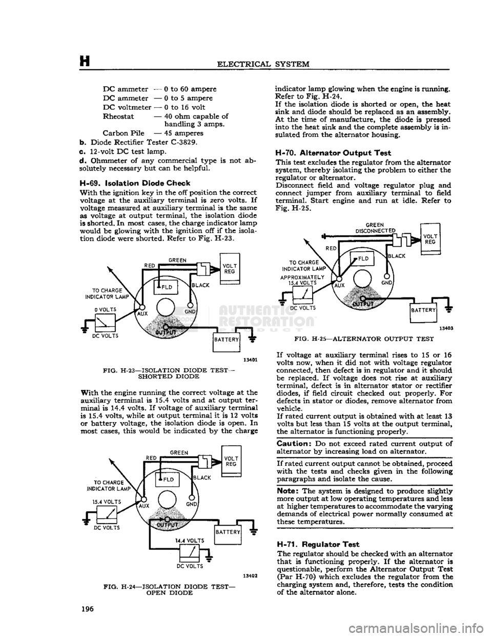
Check
With
the ignition key in the off position the correct voltage at the auxiliary terminal is zero volts. If
voltage measured at auxiliary terminal is the same as voltage at output terminal, the isolation diode
is shorted. In most cases, the charge indicator lamp
would be glowing with the ignition off if the isola tion diode were shorted. Refer to Fig. H-23.
GREEN
DC
VOLTS
13401
FIG.
H-23—ISOLATION DIODE
TEST-
SHORTED DIODE
With
the engine running the correct voltage at the
auxiliary
terminal is 15.4 volts and at output ter
minal
is 14.4 volts. If voltage of auxiliary terminal
is 15.4 volts, while at output terminal it is 12 volts
or
battery voltage, the isolation diode is open. In
most cases, this would be indicated by the charge
GREEN
TO
CHARGE
INDICATOR
LAMP1
15.4
VOLTS BLACK
VOLT
REG DC
VOLTS
BATTERY
DC
VOLTS
FIG.
H-24—ISOLATION DIODE
TEST-
OPEN DIODE
indicator
lamp glowing when the engine is running.
Refer
to Fig. H-24.
If
the isolation diode is shorted or open, the heat
sink
and diode should be replaced as an assembly.
At
the time of manufacture, the diode is pressed into the heat sink and the complete assembly is in
sulated from the alternator housing.
H-70.
Alternator Output Test
This
test
excludes the regulator from the alternator
system, thereby isolating the problem to either the regulator or alternator. Disconnect field and voltage regulator plug and
connect jumper from auxiliary terminal to field
terminal.
Start
engine and run at idle. Refer to
Fig.
H-25.
DC
VOLTS
13403
FIG.
H-25—ALTERNATOR OUTPUT
TEST
If
voltage at auxiliary terminal rises to 15 or 16
volts now, when it did not with voltage regulator
connected, then defect is in regulator and it should
be replaced. If voltage
does
not rise at auxiliary
terminal,
defect is in alternator stator or rectifier diodes, if field circuit checked out properly. For
defects
in stator or diodes, remove alternator from vehicle.
If
rated current output is obtained with at least 13
volts but less than 15 volts at the output terminal,
the alternator is functioning properly.
Caution:
Do not exceed rated current output of
alternator
by increasing load on alternator.
If
rated
current
output cannot be obtained, proceed
with
the
tests
and checks given in the following
paragraphs
and isolate the cause.
Note: The system is designed to produce slightly
more output at low operating temperatures and less
at higher temperatures to accommodate the
varying
demands of electrical power normally consumed at
these
temperatures.
H-71.
Regulator Test
The
regulator should be checked with an alternator
that is functioning properly. If the alternator is questionable, perform the Alternator Output Test
(Par
H-70) which excludes the regulator from the
charging
system and, therefore,
tests
the condition
of the alternator alone. 196
Page 209 of 376
'Jeep'
UNIVERSAL
SERIES SERVICE
MANUAL
H
H-111.
Brushes
Check
brush length. If brushes are worn to one-
half
their original length, replace them. Also check
for
cracks,
chips, damaged mounting holes, oil
saturation,
or other damage; replace brushes.
H-112.
Commutator
Check
the commutator for wear and discoloration.
If
the commutator is rough or worn the armature
should be removed and the commutator turned
down in a lathe. A discolored commutator should
be cleaned with carbon tetrachloride and inspected.
Scratches
on the commutator may be removed
with
sand paper. Use compressed air to remove
sand
particles after cleaning.
H-113.
Armature
Visually
inspect the armature for mechanical
defects
before checking for shorted or grounded
coils. Use a set of
test
probes for testing armature
circuits.
To
test
the armature for grounds, touch
one point of the
test
probes to a commutator
seg
ment and touch the other point to the core or shaft.
Do not touch the points to the bearing surface or
to the brush surface as the arc formed
will
burn
the smooth finish. If the lamp lights, the coil con
nected to the commutator
segment
is grounded.
H-114.
Field
Coils
Using
test
probes, check the field coils for both ground and open circuits. To
test
for ground, place
one probe on the motor frame or
pole
piece and
touch the other probe to the field coil terminals.
If
a ground is present, the lamp
will
light.
To
test
for open circuits, place the probes on the
field coil terminal and on an insulated
brush.
If
the light
does
not light, the coil is open circuited.
H-115.
Brush
Holder Inspection
Inspect
brush
holders for distortion, wear, and other
damage.
Check
that brush holders pivot freely on
their
pivot pins.
Check
brush spring tension with
a
spring scale. Hook the spring scale under the
brush
holder at the brush and
pull
on a line
paral
lel
to the side of the
brush.
Note
scale reading just
as brush leaves commutator. Tension must be 35 oz. [9,925 kg.] minimum. Replace brush springs
if
tension is insufficient.
H-116.
Solenoid
Coils
Check
solenoid coil as follows:
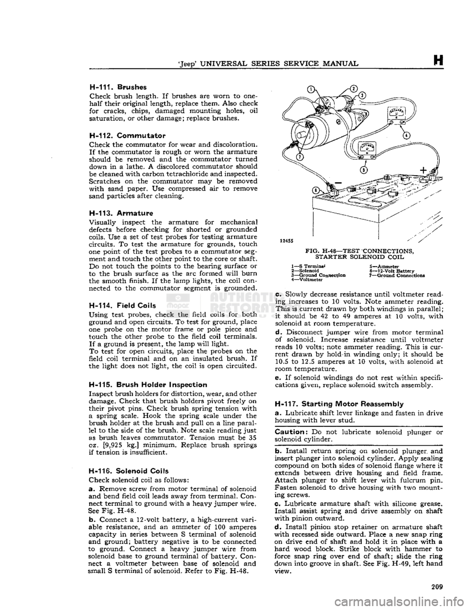
a.
Remove screw from motor terminal of solenoid
and
bend field coil leads away from terminal.
Con
nect terminal to ground with a heavy jumper wire.
See
Fig.
H-48.
b.
Connect a 12-volt battery, a high-current
vari
able resistance, and an ammeter of 100 amperes
capacity
in series
between
S terminal of solenoid
and
ground; battery negative is to be connected
to ground. Connect a heavy jumper wire from
solenoid base to ground terminal of battery.
Con
nect a voltmeter
between
base of solenoid and
small
S terminal of solenoid. Refer to Fig. H-48.
12455
FIG.
H-48—TEST CONNECTIONS,
STARTER
SOLENOID
COIL
1— S
Terminal
2—
Solenoid
3—
Ground
Connection 4—Voltmeter 5—Ammeter
6—
12-Volt
Battery
7—
Ground
Connection*
c.
Slowly decrease resistance until voltmeter
read
ing increases to 10 volts.
Note
ammeter reading.
This
is current drawn by both windings in
parallel
;
it
should be 42 to 49 amperes at 10 volts, with solenoid at room temperature.
d.
Disconnect jumper wire from motor terminal
of solenoid. Increase resistance until voltmeter
reads
10 volts;
note
ammeter reading.
This
is
cur
rent
drawn by hold-in winding only; it should be 10.5 to 12.5 amperes at 10 volts, with solenoid at
room temperature.
e. If solenoid windings do not rest within specifi cations given, replace solenoid switch assembly.
H-117.
Starting Motor Reassembly
a.
Lubricate
shift lever linkage and fasten in drive housing with lever stud.
Caution:
Do not lubricate solenoid plunger or solenoid cylinder.
b.
Install
return spring on solenoid plunger and
insert
plunger into solenoid cylinder. Apply sealing
compound on both sides of solenoid flange where it
extends
between
drive housing and field frame.
Attach
plunger to shift lever with fulcrum pin.
Fasten
solenoid to drive housing with two mount
ing screws.
c.
Lubricate
armature shaft with silicone grease.
Install
assist spring and drive assembly on shaft
with
pinion outward.
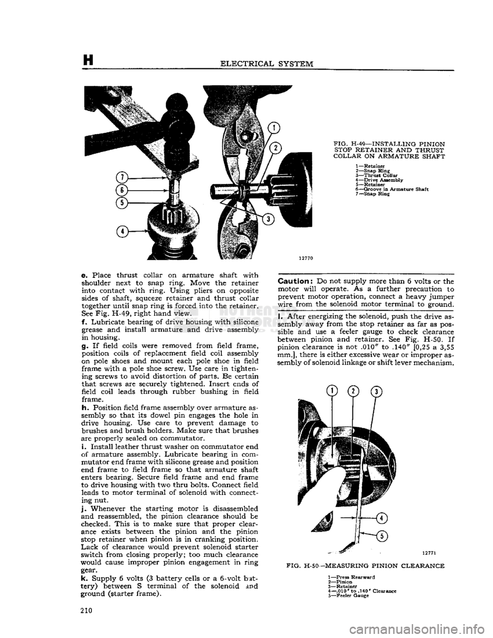
d.
Install
pinion
stop
retainer on armature shaft
with
recessed side outward. Place a new snap ring on drive end of shaft and hold it in place with a
hard
wood block. Strike block with hammer to
force snap ring over end of shaft; slide the ring
down into
groove
in shaft. See Fig. H-49, left hand view. 209
Page 210 of 376
H
ELECTRICAL
SYSTEM
FIG.
H-49—INSTALLING PINION
STOP RETAINER AND THRUST
COLLAR
ON ARMATURE SHAFT
1—
Retainer
2—
Snap
Ring
3—
Thrust
Collar
4—
Drive
Assembly 5—
Retainer
6—
Groove
in Armature Shaft 7—
Snap
Ring
e. Place thrust collar on armature shaft with shoulder next to snap
ring.
Move the retainer
into contact with
ring.
Using pliers on
opposite
sides of shaft,
squeeze
retainer and thrust collar
together
until snap ring is forced into the retainer.
See Fig. H-49, right hand view.
f.
Lubricate
bearing of drive housing with silicone grease and install armature and drive assembly
in
housing.
g. If field coils were removed from field frame, position coils of replacement field coil assembly
on
pole
shoes
and mount each
pole
shoe
in field
frame
with a
pole
shoe
screw. Use care in tighten ing screws to avoid distortion of parts. Be certain
that screws are securely tightened. Insert ends of
field
coil
leads through rubber bushing in field
frame.
h.
Position field frame assembly over armature as
sembly so that its dowel pin
engages
the
hole
in
drive
housing. Use care to prevent damage to brushes and brush holders. Make sure that brushes
are
properly sealed on commutator.
i.
Install
leather thrust washer on commutator end
of armature assembly.
Lubricate
bearing in com
mutator end frame with silicone grease and position
end frame to field frame so that armature shaft
enters bearing. Secure field frame and end frame
to drive housing with two
thru
bolts. Connect field leads to motor terminal of solenoid with connecting nut.
j.
Whenever the starting motor is disassembled
and
reassembled, the pinion clearance should be
checked.
This
is to make sure that proper clear
ance exists
between
the pinion and the pinion
stop
retainer when pinion is in cranking position.
Lack
of clearance would prevent solenoid starter
switch
from closing properly; too much clearance
would cause improper pinion
engagement
in ring gear.
k.
Supply 6 volts (3 battery cells or a
6-volt
bat
tery)
between
S terminal of the solenoid and ground (starter frame).
Caution:
Do not supply more than 6 volts or the
motor
will
operate. As a further precaution to
prevent motor operation, connect a heavy jumper
wire
from the solenoid motor terminal to ground.
I.
After energizing the solenoid, push the drive as
sembly away from the
stop
retainer as far as pos
sible and use a feeler
gauge
to check clearance
between
pinion and retainer. See Fig. H-50. If pinion clearance is not .010" to .140" [0,25 a 3,55
mm.],
there is either excessive wear or improper as
sembly of solenoid linkage or shift lever mechanism.
12771
FIG.
H-50—MEASURING PINION CLEARANCE
1—
Press
Rearward
2—
Pinion
3—
Retainer
4— .010* to .140* Clearance 5—
Feeler
Gauge
210
Page 211 of 376
'Jeep'
UNIVERSAL
SERIES SERVICE
MANUAL
H
Note:
Pinion clearance cannot be adjusted. If
clearance is not correct, motor must be disassem
bled and checked for the above mentioned defects.
Any
defective parts must be replaced.
H-118. Starting Motor Test —
Genera!
To
obtain
full
performance data on a starting motor, or to determine the cause of abnormal
operation, the motor should be submitted to no-
load and locked armature
tests,
with equipment designed for such
tests.
A high-current variable resistance is required to obtain the specified volt
age at the starting motor.
This
is necessary since
a
small variation in the
voltage
will
produce a
marked
difference in the current
drawn.
H-119.
Starting Motor No-Load Test
This
test
requires a DC voltmeter capable of
read
ing
voltages
in a 12-volt
circuit,
a DC ammeter
with
maximum range of several hundred amperes,
a
high-current variable resistance, an rpm. in
dicator,
and a fully-charged, 12-volt battery.
a.
Connect a jumper lead
between
S terminal
and
large battery terminal of starter solenoid.
Con
nect voltmeter
between
either of
these
terminals (positive) and motor frame (negative, ground).
Connect
ammeter and variable resistance in series
between
positive terminal of battery and battery
terminal
of solenoid. Set up rpm. indicator to show starting motor speed.
b.
Initially,
adjust variable resistance to a value of
approximately .25 ohm. To complete the
circuit,
connect negative terminal of battery to motor
frame.
Adjust variable resistance to obtain a volt meter reading of 10.6 volts;
note
speed of starting motor and ammeter reading. Motor speed should
be
6750
to
10,500
rpm.; ammeter reading should
be 50 to 80 amperes.
c. Rated speed and current indicate normal condi
tion of the starting motor. Low speed and high
cur
rent
may show friction; this could be caused by
tight, dirty, or worn bearings, bent armature shaft,
or
a
loose
field
pole
shoe
dragging against the
armature.
It could also be caused by a short-cir cuited armature, or by grounded armature or field
coils.
d.
Failure
to operate and high current indicates
a
direct short circuit to ground at either the battery
terminal
or field coils.
e.
Failure
to operate and no current are usually
caused by broken brush springs, worn brushes, high insulation
between
commutator
bars,
or
some
other
condition preventing
good
contact
between
the brushes and commutator. It can also be caused by
open circuit in either the field coils or armature coils.
f. Low speed and low current show high resistance due to poor connections, defective leads, dirty com
mutator, or one of the conditions mentioned in e,
above.
g. High speed and high current indicates a short
circuit
in the field coils. H-120-
Locked
Armature Test
This
test
requires a DC voltmeter with range ap
propriate
to read
voltages
in a 12-volt
circuit,
a DC
ammeter with maximum range of several hundred
amperes, a high-current variable resistance, a
clamping fixture to lock
together
the motor shaft
and
case, and a fully-charged 12-volt battery.
a.
Connect a jumper lead
between
S terminal and
large battery terminal of starter solenoid. Connect
voltmeter
between
either of
these
terminals (posi
tive) and motor frame (negative, ground). Connect
ammeter and variable resistance in series
between
positive terminal of battery and battery terminal
of solenoid.
Install
clamping fixture to lock motor
shaft and case
together
securely.
b.
Initially,
adjust variable resistance to approxi
mately .05 ohm. To complete the
circuit,
connect
negative terminal of battery to motor frame. Ad
just
variable resistance to obtain a voltmeter
read
ing of 4.0 volts. Ammeter reading should be 280
to 320 amperes.
H-121.
Solenoid Starter Switch — Delco
The
solenoid-type switch is mounted directly on
the starting motor.
This
type of switch is energized
by turning the ignition key to the extreme right position. Should the solenoid switch
fail
in service
it
is necessary to install a new assembly.
Should
a starting motor
fail
to deliver maximum power the fault may be due to
voltage
drop at the
starter
switch contacts due to corrosion or burning.
Check
the switch by comparing the
voltage
at the
battery across the terminals. The
voltage
drop
should not exceed .05 volts per 100 amperes.
In
order to remove the starter solenoid, it is neces
sary
to remove the starter assembly.
H-122.
ELECTRICAL
INSTRUMENTS
H-123.
Fuel
Gauge —
CJ-3B
The
fuel
gauge
circuit is composed of the indicating
unit,
mounted on the instrument panel, and the
fuel tank unit, connected by a single wire through the ignition switch.
Should
the
gauge
fail
to register, check all wire con nections to be sure they are tight and clean; also
be sure both units are well grounded. If, after this
check, the
gauge
does
not indicate properly, remove
the wire from the tank unit and connect it to a
new tank unit which must be grounded to the tank
or
frame for
test.
Turn
the ignition switch "ON"
and
move
the float arm through its range of travel,
watching the dash unit to determine if it indicates
correctly.
If it fails to do so the trouble is probably
in
the dash unit and it should be replaced.
Should
a new tank unit be unavailable for this
test,
disconnect tank unit wire at the instrument panel
gauge.
Connect one lead of a 12 V, 1 CP
test
light
to the instrument panel unit terminal and with the
ignition switch
"ON"
ground the other lead. If the
unit is operating correctly the pointer
will
move
approximately three-quarter across the
dial.
Do not attempt to repair either unit; replacement
is the only precedure. 211