clock reset JEEP CJ 1953 Service Manual
[x] Cancel search | Manufacturer: JEEP, Model Year: 1953, Model line: CJ, Model: JEEP CJ 1953Pages: 376, PDF Size: 19.96 MB
Page 24 of 376

c
TUNE-UP
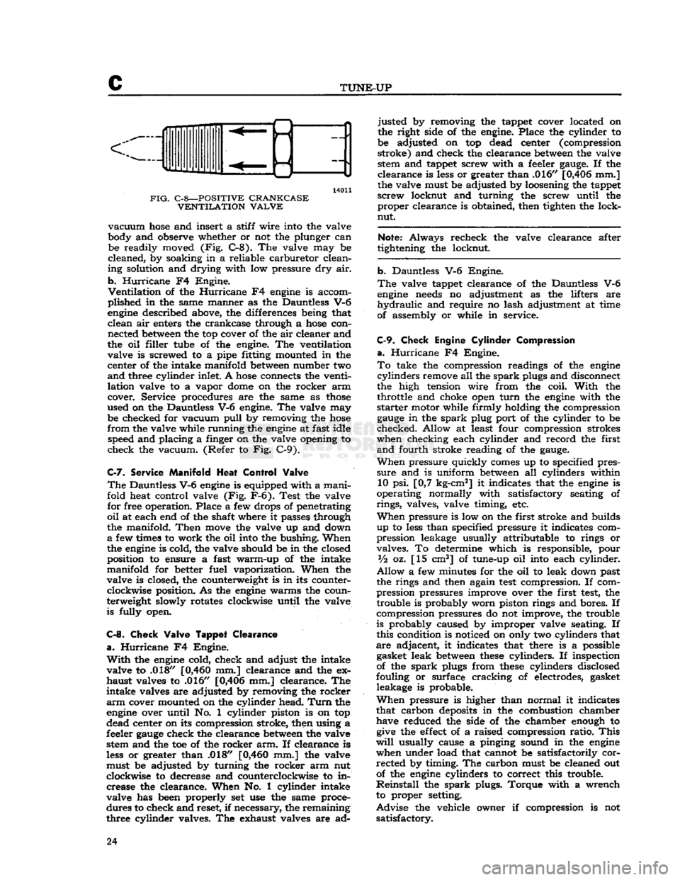
14011
FIG.
C-8—POSITIVE CRANKCASE VENTILATION VALVE
vacuum
hose
and insert a stiff wire into the valve
body and observe whether or not the plunger can be readily moved (Fig. C-8). The valve may be
cleaned, by soaking in a reliable carburetor clean
ing solution and drying with low pressure dry air.
b.
Hurricane
F4 Engine.
Ventilation
of the
Hurricane
F4
engine
is accom
plished in the same manner as the Dauntless V-6
engine
described above, the differences being that clean air enters the crankcase through a
hose
con nected
between
the top cover of the air cleaner and
the oil filler tube of the engine. The ventilation valve is screwed to a pipe fitting mounted in the
center of the intake manifold
between
number two
and
three cylinder inlet. A
hose
connects the venti
lation valve to a vapor
dome
on the rocker arm
cover. Service procedures are the same as
those
used on the Dauntless V-6 engine. The valve may be checked for vacuum
pull
by removing the
hose
from
the valve while running the
engine
at fast idle speed and placing a finger on the valve opening to
check the vacuum. (Refer to Fig. C-9).
C-7.
Service
Manifold
Heat
Control
Valve
The
Dauntless V-6
engine
is equipped with a manifold heat control valve (Fig. F-6). Test the valve
for free operation. Place a few drops of penetrating
oil
at each end of the shaft where it passes through
the manifold.
Then
move
the valve up and down
a
few times to work the oil into the bushing. When
the
engine
is cold, the valve should be in the closed
position to ensure a fast warm-up of the intake
manifold for better fuel vaporization. When the
valve is closed, the counterweight is in its counter clockwise position. As the
engine
warms the coun
terweight slowly rotates clockwise until the valve is fully open.
C-8.
Check
Valve
Tappet
Clearance
a.
Hurricane
F4 Engine.
With
the
engine
cold, check and adjust the intake
valve to .018"
[0,460
mm.] clearance and the ex
haust valves to .016" [0,406 mm.] clearance. The
intake valves are adjusted by removing the rocker
arm
cover mounted on the cylinder head.
Turn
the
engine
over until No. 1 cylinder piston is on top
dead center on its compression stroke, then using a
feeler
gauge
check the clearance
between
the valve stem and the toe of the rocker arm. If clearance is
less
or greater than .018"
[0,460
mm.] the valve
must be adjusted by turning the rocker arm nut
clockwise to decrease and counterclockwise to in crease the clearance. When No. 1 cylinder intake
valve has been properly set use the same proce
dures to check and reset, if necessary, the remaining
three cylinder valves. The exhaust valves are ad justed by removing the tappet cover located on
the right side of the engine. Place the cylinder to
be adjusted on top dead center (compression stroke) and check the clearance
between
the valve stem and tappet screw with a feeler
gauge.
If the
clearance is
less
or greater than .016" [0,406 mm.]
the valve must be adjusted by loosening the tappet
screw locknut and turning the screw until the proper clearance is obtained, then tighten the lock-
nut.
Note:
Always recheck the valve clearance after
tightening the locknut.
b. Dauntless V-6 Engine.
The
valve tappet clearance of the Dauntless V-6
engine
needs
no adjustment as the lifters are
hydraulic
and require no lash adjustment at time
of assembly or while in service.
C-9.
Check
Engine
Cylinder
Compression
a.
Hurricane
F4 Engine.
To
take the compression readings of the
engine
cylinders
remove all the
spark
plugs and disconnect
the high tension wire from the coil.
With
the throttle and choke open
turn
the
engine
with the
starter
motor while firmly holding the compression
gauge
in the
spark
plug port of the cylinder to be
checked. Allow at least four compression strokes
when checking each cylinder and record the first
and
fourth stroke reading of the
gauge.
When
pressure quickly
comes
up to specified pres
sure
and is uniform
between
all cylinders within 10 psi. [0,7 kg-cm2] it indicates that the
engine
is
operating normally with satisfactory seating of
rings,
valves, valve timing, etc.
When
pressure is low on the first stroke and builds
up to
less
than specified pressure it indicates com
pression leakage usually attributable to rings or
valves. To determine which is responsible, pour
Vz
oz. [15 cm3] of tune-up oil into each cylinder.
Allow
a few minutes for the oil to leak down past
the rings and then again
test
compression. If com
pression pressures improve over the first
test,
the trouble is probably worn piston rings and bores. If
compression pressures do not improve, the trouble
is probably caused by improper valve seating. If
this condition is noticed on only two cylinders that
are adjacent, it indicates that there is a possible gasket leak
between
these
cylinders. If inspection
of the
spark
plugs from
these
cylinders disclosed
fouling or surface cracking of electrodes, gasket leakage is probable.
When
pressure is higher than normal it indicates
that carbon
deposits
in the combustion chamber have reduced the side of the chamber enough to
give
the
effect
of a raised compression ratio.
This
will
usually cause a pinging sound in the
engine
when under load that cannot be satisfactorily corrected by timing. The carbon must be cleaned out
of the
engine
cylinders to correct this trouble.
Reinstall
the
spark
plugs. Torque with a wrench
to proper setting.
Advise
the vehicle owner if compression is not satisfactory. 24
Page 69 of 376

'Jeep9
UNIVERSAL
SERIES
SERVICE
MANUAL
h.
Check
ignition (distributor) timing; reset if
necessary.
i.
Check
carburetor
adjustments; reset if necessary,
j.
With
engine
fully warmed up, tighten cylinder
head and manifold
bolts
and nuts to specified
torque.
Check
cylinder head gaskets and
bolts
for
air
or coolant leaks.
Note:
Tightness of cylinder head
bolts
should be
checked and corrected after 500 to 600 miles [800
a
960 km.] of normal operation.
k.
Check
fan belt tension; adjust if necessary.
I.
Check
for and correct any oil leak, fuel leak or
coolant leak.
D-107.
VALVE
ADJUSTMENT
Proper
valve adjustment is important to prevent
burning
of valves and poor
engine
performance.
This
adjustment consists of obtaining a specified
lash
in the valve mechanism. The exhaust valve
tappets and the intake valve rocker arms should be adjusted to the proper clearance with the
engine
cold (at room temperature). Valve clearance can
be properly adjusted only when the tappet is on the
heel or low portion of the cam.
INTAKE
OPENS
9°
BTC?
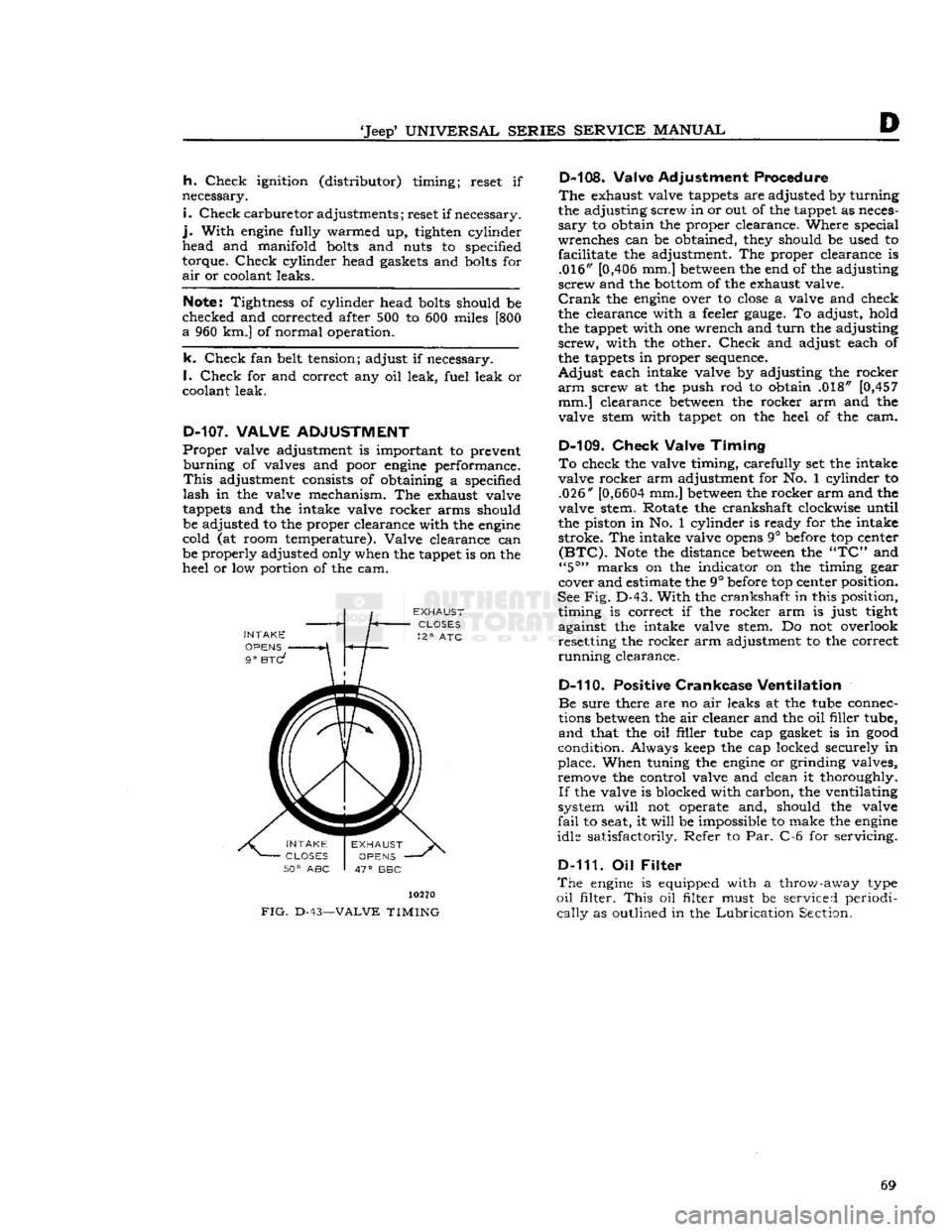
FIG.
D-43-
10270
-VALVE
TIMING
D-108. Valve Adjustment Procedure
The
exhaust valve tappets are adjusted by turning
the adjusting screw in or out of the tappet as neces
sary
to obtain the proper clearance. Where special
wrenches can be obtained, they should be used to facilitate the adjustment. The proper clearance is .016" [0,406 mm.]
between
the end of the adjusting
screw and the
bottom
of the exhaust valve.
Crank
the
engine
over to
close
a valve and check
the clearance with a feeler
gauge.
To adjust, hold
the tappet with one wrench and
turn
the adjusting
screw,
with the other.
Check
and adjust each of
the tappets in proper sequence.
Adjust
each intake valve by adjusting the rocker
arm
screw at the push rod to obtain .018" [0,457 mm.] clearance
between
the rocker arm and the
valve stem with tappet on the heel of the cam.
D-109.
Check
Valve
Timing
To
check the valve timing, carefully set the intake
valve rocker arm adjustment for No. 1 cylinder to .026"
[0,6604
mm.]
between
the rocker arm and the
valve stem. Rotate the crankshaft clockwise until
the piston in No. 1 cylinder is ready for the intake stroke. The intake valve
opens
9° before top center
(BTC).
Note
the distance
between
the
"TC"
and
"5°"
marks on the indicator on the timing gear
cover and estimate the 9° before top center position.
See
Fig.
D-43.
With
the crankshaft in this position, timing is correct if the rocker arm is just tight
against the intake valve stem. Do not overlook resetting the rocker arm adjustment to the correct
running
clearance.
D-110. Positive
Crankcase
Ventilation
Be
sure there are no air leaks at the tube connec
tions
between
the air cleaner and the oil filler tube,
and
that the oil filler tube cap gasket is in
good
condition. Always keep the cap locked securely in
place. When tuning the
engine
or grinding valves, remove the control valve and clean it thoroughly.
If
the valve is blocked with carbon, the ventilating
system
will
not operate and, should the valve
fail
to seat, it
will
be impossible to make the
engine
idle satisfactorily. Refer to Par. C-6 for servicing.
D-111. Oil
Filter
The
engine
is equipped with a throw-away type
oil
filter.
This
oil filter must be serviced periodi
cally
as outlined in the
Lubrication
Section. 69
Page 145 of 376

'Jeep'
UNIVERSAL
SERIES SERVICE
MANUAL
Fl
b. Connect tachometer to
engine.
c.
Warm
up
engine
and stabilize temperatures.
d.
Adjust
engine
idle to
speed
desired, using throt
tle idle
speed
adjusting screw.
e.
Carburetors without Idle
Limiter
Cap turn idle mixture screws out (counterclockwise) until a
loss
of
engine
speed
is indicated; then, slowly turn mix
ture screw in (clockwise-leaner) until maximum
speed
(RPM) is reached. Continue turning in (clockwise) until
speed
begins
to drop; turn mixture
adjustment back out (counterclockwise-richer) un
til
maximum
speed
is just regained at a "lean as
possible" mixture adjustment.
Fl-14.
Distributor
Check
the distributor number for proper appli
cation.
Check
the distributor cam dwell angle and
point condition and adjust to specifications or re place as required. (Specifications listed at the end
of this section)
Check
ignition timing and set at
0°
or
TDC.
Fl-15.
Anti-iackfire
Diverter Valve
The
anti-backfire valve remains closed
except
when
the throttle is closed rapidly from an
open
position.
To
check the valve for proper operation, accelerate
the
engine
in neutral, allowing the throttle to
close
rapidly.
The valve is operating satisfactorily when
no exhaust system backfire occurs. A further check
to determine whether the valve is functioning can be made by removing from the anti-backfire valve
the large
hose
Which
connects to the check valve.
Accelerate the
engine
to allow the throttle to
close
rapidly.
The valve is operating satisfactorily if a
momentary interruption of rushing air is audible.
Fl-16.
Check Valve
The
check valve prevents the reverse flow of ex
haust
gases
to the pump in the
event
the pump
should, for any reason,
become
inoperative or should exhaust pressure ever
exceed
pump pressure.
To
check this valve for proper operation, remove the air supply
hose
from the pump at the
distri
bution manifold.
With
the
engine
running, listen for exhaust leakage at the check valve which is
connected to the distribution manifold.
Fl-17.
Air
Pump
Check
for proper drive belt tension with belt tension
gauge
W-283. The belt strand tension should be
50-60
pounds on a belt with previous service, meas
ured
on the
longest
accessible span
between
two pulleys. When installing a new belt, adjust the
tension to
60-80
pounds tension. DO NOT PRY
ON
THE DIE
CAST
PUMP
HOUSING.
To
check the pump for proper operation, remove the air
outlet
hose
at the pump.
With
the
engine
running,
air discharge should be
felt
at the pump
outlet
opening. The pump
outlet
air pressure, as determined by the relief valve, is preset and is not
adjustable.
The
air pump
rear
cover assembly, housing the pressed in inlet and discharge tubes, and the pres
sure relief valve are the only pump
components
recommended for service replacement. These parts
are
to be replaced only when damaged as a result
of handling or in the
event
the relief valve was
tampered with.
Fl-18.
Carburetor
Air
Cleaner
Every
6000
miles
[9,600
km.] clean the inside
sur
face at the sump and
refill
to indicated oil level with
SAE
40 or 50
engine
oil
above
32 F; SAE 20
below
32 F. Wash filter
element
in kerosene and
drain.
Reassemble the air cleaner.
More
frequent cleaning and replacement is advis able when the car is operated in dusty areas or on
unpaved roads. Accumulated dirt restricts air flow,
reducing fuel
economy
and performance.
Fl-19.
REMOVAL
PROCEDURES
The
following paragraphs
give
the procedures for removing the major units of the Exhaust Emission
Control
System and the required equipment
needed.
Fl-20.
Air
Pump
Loosen
the air pump adjusting strap to facilitate
drive
belt removal. Remove the air pump air dis
charge hose(s) and air filter attachment. Separate
the air pump from its mounting bracket. At time of installation, torque tighten the air pump mounting
bolts
to
30-40
lbs-ft. [4,15 a 5,53 kg-m.]. Adjust
the belt strand tension to
50-60
pounds on a belt
with previous service and
60-80
pounds on a new
belt.
Fl-21.
Anti-Backfire
Diverter Valve
The
anti-backfire diverter valve removal requires disconnecting the
hoses
and bracket to
engine
at
taching screws.
Fl-22.
Air
Distribution
Manifold
and
Injection Tubes
In
order to remove the air distribution manifold
without bending the tubing, which could result in
fractures
or leakage, it is necessary to remove the
exhaust manifold as an assembly from the
engine.
After
the exhaust manifold assembly is removed
from
the
engine,
place the manifold in a vise and
loosen
the air distribution manifold
tube
retaining nuts at each cylinder exhaust port. Tap the injec
tion
tubes
lightly to allow the air distribution mani
fold to be pulled away partially from the exhaust manifold. The stainless steel injection
tubes
in the
exhaust manifold may have
become
partially fused
to the air distribution manifold and, therefore, may
require
application of heat to the joint in order to
separate. While applying heat to the joint, rotate
the injection
tubes
with pliers being careful not to
damage the
tubes
by applying excessive force.
At
time of installation, the air injection
tubes
must
be positioned into the exhaust manifold prior to
placing the exhaust manifold assembly on the en gine.
Note:
Two different length injection
tubes
are used.
The
shorter length injection
tubes
must be inserted into cylinders 1 and 4. 145
Page 156 of 376

F2
EXHAUST EMISSION CONTROL SYSTEMS
the throttle
stop
screw to idle the
engine
at 650
to 700 rpm.
F2-17. Carburetor Idle Setting
The
"Lean
Best
Idle"
Method of Idle Setting is as
follows:
a.
Any scheduled service of ignition system should
precede this adjustment
b.
Connect tachometer to engine.
c.
Warm
up
engine
and stabilize temperatures.
d.
Adjust
engine
idle to speed desired, using throt
tle idle speed adjusting screw.
e.
Turn
idle mixture screws out (counterclockwise)
until
a
loss
of
engine
speed is indicated; then slowly
turn
mixture screws in (clockwise-leaner)
until
maximum speed (rpm) is reached. Continue
turning
in (clockwise) until speed begins to drop;
turn
mixture adjustment back out (counterclock
wise-richer)
until maximum speed is just regained
at
a "lean as possible" mixture adjustment.
F2-18. Distributor
The
ignition distributor used with the
Exhaust
Emission
Control
System is the same as that used
on
engines
without
Exhaust
Emission
Control.
Check
the distributor cam dwell angle and point
condition.
Check
ignition timing and adjust to specifications shown on the last
page
of this section.
F2-19.
Anti-Backfire
Valve
The
anti-backfire valve remains closed except when
the throttle is closed rapidly from an open position.
To
check the valve for proper operation, accelerate
the
engine
in neutral, allowing the throttle to close
rapidly.
The valve is operating satisfactorily when
no exhaust system backfire occurs. A further check
to determine whether the valve is functioning can
be made by removing from the anti-backfire valve
the large
hose
which connects the valve to the
pump.
With
a finger placed over the open end of
the
hose
(not the valve), accelerate the
engine
and allow the throttle to close rapidly. The valve is
operating satisfactorily if a momentary air rushing
noise is audible.
F2-20.
Check
Valve
The
check valves in the lines to the air distribution manifolds prevent the reverse flow of exhaust
gases
to the pump in the event the pump should, for
any
reason,
become
inoperative or should exhaust
pressure
ever exceed pump pressure.
To
check this valve for proper operation, remove the air supply
hose
from the pump at the check
valve.
With
the
engine
running, listen for exhaust
leakage at the check valve which is connected to
the distribution manifold.
F2-21.
Air
Pump
Check
for proper drive belt tension with belt tension
gauge
W-283. The belt strand tension should be 60 pounds measured on the
longest
accessible span
between two pulleys. DO NOT PRY ON THE
DIE
CAST
PUMP
HOUSING. To
check the pump for proper operation, remove
the air
outlet
hose
at the pump.
With
the
engine
running,
air discharge should be felt at one of
the pump
outlet
openings. The pump
outlet
air
pressure,
as determined by the relief valve, is preset
and
is not adjustable.
The
air pump
rear
cover assembly, housing the pressed in inlet and discharge tubes, and the pres
sure
relief valve are the only pump components
recommended for service replacement. These parts
are
to be replaced only when damaged as a result
of handling or in the event the relief valve was
tampered with.
F2-22.
Intake Manifold
Intake
manifold leaks must not be overlooked. Air
leakage at the intake manifold may be compen
sated for by
richer
idle mixture setting, however, this
will
usually cause uneven fuel-air distribution
and
will
always result in
loss
of performance and
exhaust emission control. To check for air leakage
into the intake manifold, apply kerosene or naph
tha,
on the intake manifold to cylinder head joints
and
observe whether any changes in
engine
rpm
occur.
If an air leak is indicated, check the mani
fold to cylinder head bolt torque. The correct torque is 25-35 lbs. ft. [3,46 a 4,84 kg-m.]. If the
leak
is
still
evident,
loosen
the manifold assembly
and
torque-tighten the bolts evenly.
Start
from the center and use proper torque values. Replace the
manifold
gasket if the leak
still
exists.
Clean
both
mating surfaces and check for
burrs
or other ir
regularities.
Always
torque the bolts evenly to the specified
torque value to prevent warpage.
F2-23.
Carburetor
Air
Cleaner
—Oil
Bath
Every
6,000
miles [9,600 km.] disconnect attach
ing
hoses
and unscrew the wing nut from the top
of the air cleaner and lift it off the carburetor.
Lift
the cover and filter element off the oil sump.
Clean
the inside surface of the sump and
refill
to
indicated
oil level with SAE 40 or 50
engine
oil
above 32 F; SAE 20 below 32 F.
Wash
filter element in kerosene and
drain.
Reassemble the air
cleaner
and install on carburetor.
More
frequent cleaning and replacement are advis able when the car is operated in dusty areas or on
unpaved
roads. Accumulated
dirt
restricts air flow,
reducing
fuel economy and performance.
F2-24.
REMOVAL PROCEDURES
The
following paragraphs
give
the procedures for removing the major units of the exhaust emission
control
system and the required equipment needed.
F2-2S.
Air
Pump
Loosen
the air pump mounting bracket bolts. Re move the air pump air hose(s). Separate the air pump from its mounting bracket. At time of install
ation,
torque tighten the air pump mounting bolts
to
30-40
lbs.-ft [4,15 a 5,53 kg-m.].
Adjust
the
belt strand tension to 60 pounds. 156