steering wheel adjustment JEEP CJ 1953 User Guide
[x] Cancel search | Manufacturer: JEEP, Model Year: 1953, Model line: CJ, Model: JEEP CJ 1953Pages: 376, PDF Size: 19.96 MB
Page 318 of 376
o
STEERING
SYSTEM
10
FIG.
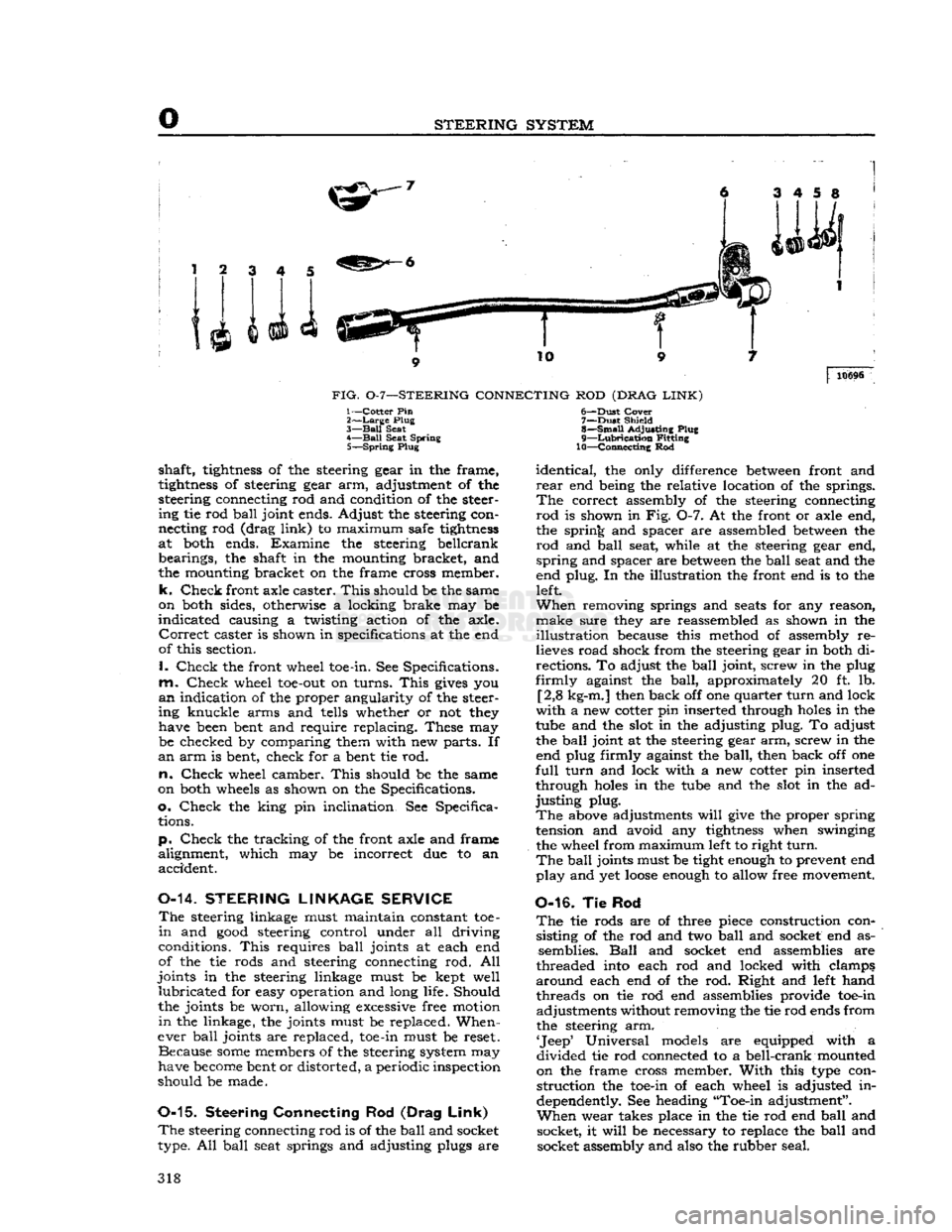
0-7—STEERING
CONNECTING
ROD
(DRAG
LINK)
10696
1—Cotter Pin
2>—Large
Plug
3—
Ball
Seat
4—
Ball
Seat Spring 5—
Spring
Plug
shaft,
tightness
of the steering gear in the frame,
tightness
of steering gear arm, adjustment of the
steering connecting rod and condition of the steer ing tie rod
ball
joint ends. Adjust the steering con
necting rod (drag
link)
to maximum safe
tightness
at both ends. Examine the steering beilcrank bearings, the shaft in the mounting bracket, and
the mounting bracket on the frame cross member,
k.
Check
front axle caster.
This
should be the same
on both sides, otherwise a locking brake may be
indicated
causing a twisting action of the axle.
Correct
caster is shown in specifications at the end
of this section.
I.
Check
the front wheel toe-in. See Specifications,
m.
Check
wheel
toe-out
on turns.
This
gives
you
an
indication of the proper angularity of the steer
ing knuckle arms and tells whether or not they have been bent and require replacing. These may be checked by comparing them with new parts. If
an
arm is bent, check for a bent tie rod.
n.
Check
wheel camber.
This
should be the same
on both wheels as shown on the Specifications,
o.
Check
the king pin inclination. See Specifica tions.
p.
Check
the tracking of the front axle and frame
alignment, which may be incorrect due to an accident.
0-14.
STEERING
LINKAGE
SERVICE
The
steering linkage must maintain constant toe-
in
and
good
steering control under all driving
conditions.
This
requires
ball
joints at each end
of the tie rods and steering connecting rod. All
joints in the steering linkage must be kept well
lubricated
for easy operation and long life. Should
the joints be worn, allowing excessive free motion
in
the linkage, the joints must be replaced. When
ever
ball
joints are replaced, toe-in must be reset. Because
some
members of the steering system may
have
become
bent or distorted, a periodic inspection
should be made.
0-15.
Steering Connecting
Rod
(Drag
Link)
The
steering connecting rod is of the
ball
and socket
type. All
ball
seat springs and adjusting plugs are 6—
-Dust
Cover
7—
Dust
Shield
8—
Small
Adjusting Plug
9—
Lubrication
Fitting
10—Connecting Rod
identical,
the only difference
between
front and
rear
end being the relative location of the springs.
The
correct assembly of the steering connecting
rod
is shown in Fig. 0-7. At the front or axle end,
the spring and spacer are assembled
between
the
rod
and
ball
seat, while at the steering gear end,
spring
and spacer are
between
the
ball
seat and the
end plug. In the illustration the front end is to the left.
When
removing springs and
seats
for any reason,
make
sure they are reassembled as shown in the
illustration
because this method of assembly re
lieves road shock from the steering gear in both di
rections. To adjust the
ball
joint, screw in the plug
firmly
against the
ball,
approximately 20 ft. lb. [2,8 kg-m.] then back off one quarter
turn
and lock
with
a new cotter pin inserted through
holes
in the
tube and the slot in the adjusting plug. To adjust the
ball
joint at the steering gear arm, screw in the end plug firmly against the
ball,
then back off one
full
turn
and lock with a new cotter pin inserted
through
holes
in the tube and the slot in the ad
justing
plug.
The
above adjustments
will
give
the proper spring
tension and avoid any
tightness
when swinging
the wheel from maximum left to right
turn.
The
ball
joints must be tight enough to prevent end
play
and yet
loose
enough to allow free movement.
0-16. Tie Rod
The
tie rods are of three piece construction consisting of the rod and two
ball
and socket end as semblies.
Ball
and socket end assemblies are
threaded into each rod and locked with clamps,
around
each end of the rod. Right and left hand threads on tie rod end assemblies provide toe-in adjustments without removing the tie rod ends from
the steering arm.
'Jeep'
Universal models are equipped with a
divided
tie rod connected to a bell-crank mounted
on the frame cross member.
With
this type con
struction
the toe-in of each wheel is adjusted in
dependently. See heading "Toe-in adjustment".
When
wear takes place in the tie rod end
ball
and socket, it
will
be necessary to replace the
ball
and socket assembly and also the rubber seal. 318
Page 336 of 376
Q
WHEELS
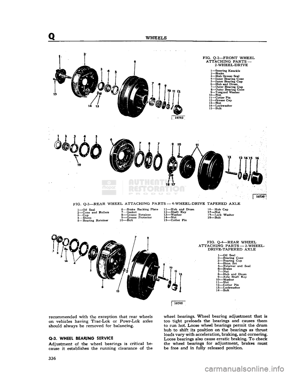
FIG.
Q-2—FRONT
WHEEL
ATTACHING
PARTS —
2-WHEEL-DRIVE
1—
Steering
Knuckle
2—
Brake
3— Hub
Grease
Seal
4—
Inner
Bearing
Cone
5—
Inner
Bearing
Cup
6—
Hub
and
Drum
7—
Outer
Bearing
Cup
8—
Outer
Bearing
Cone
9—
Tongued
Washer
10— Nut
11—
Cotter
Pin
12—
Grease
Cap
13— Nut
14—
Lockwasher
15—
Bolt
j
10703
is ir 10730
FIG.
Q-3—REAR
WHEEL
ATTACHING PARTS —
4-WHEEL-DRIVE
TAPERED
AXLE
1—
Oil
Seal
2—
Cone
and
Rollers
3— Cup
4—
Shims
5—
Bearing
Retainer
6—
Brake
Backing
Plate
7—
Gasket
8—
Grease
Retainer
9—
Grease
Protector
10—Bolt
11— Hub
and
Drum
12—
Shaft
Key
13—
Washer
14—
Nut
15—
Cotter
Pin
Ifi—Hub
Cap
17—Nut
18—
Ixick
Washer
19—Bolt
FIG.
Q-4—REAR
WHEEL
ATTACHING
PARTS —
2-WHEEL-
DRIVE-TAPERED
AXLE
1—
Oil
Seal
2—
Bearing
Cone
3—
Bearing
Cup
4—
Shim
Set
5—
Retainer
and
Seal
6—
Brake
7—
Nut
8—
Hub
and
Drum
9—
Axle
Shaft Key
10—
Washer
11— Nut
12—
Cotter
Pin
13—
Lockwasher
14—
Bolt
recommended with the exception that
rear
wheels
on vehicles having
Trac-Lok
or
Powr-Lok
axles
should always be removed for balancing.
Q-3. WHEEL
BEARING
SERVICE
Adjustment
of the wheel bearings is
critical
be cause it establishes the running clearance of the wheel bearings. Wheel bearing adjustment that is
too
tight
preloads the bearings and causes them
to run hot. Loose wheel bearings permit the drum hub to shift its position on the bearings as thrust loads
vary
with acceleration,
braking,
and cornering.
Loose
bearings also cause
erratic
braking.
To check
the wheel bearings for adjustment, brakes must
be free and in fully released position. 336
Page 337 of 376
'Jeep'
UNIVERSAL
SERIES SERVICE
MANUAL
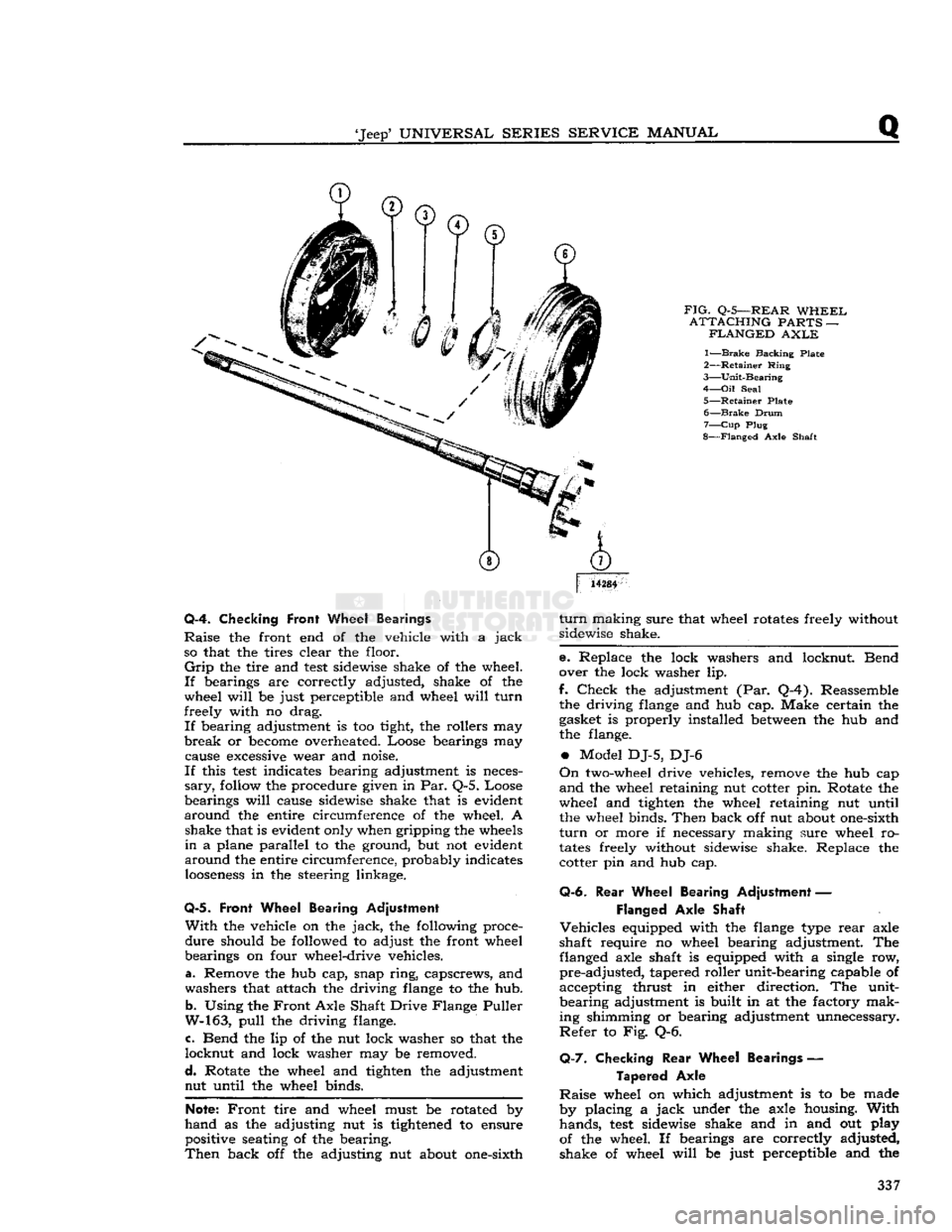
FIG.
Q-5—REAR
WHEEL
ATTACHING
PARTS —
FLANGED
AXLE
1—
Brake
Backing Plate
2—
Retainer
Ring
3—
Unit-Bearing
4—
Oil
Seal
5—
Retainer
Plate 6—
Brake
Drum
7—
Cup
Plug
8—
Flanged
Axle Shaft
14284
Q-4. Checking
Front
Wheel Bearings
Raise
the front end of the vehicle with a
jack
so that the tires clear the floor.
Grip
the tire and
test
sidewise shake of the wheel.
If
bearings are correctly adjusted, shake of the
wheel
will
be just perceptible and wheel
will
turn
freely with no drag.
If
bearing adjustment is too tight, the rollers may
break
or
become
overheated. Loose bearings may cause
excessive
wear and noise.
If
this
test
indicates bearing adjustment is neces
sary,
follow
the procedure given in Par. Q-5. Loose
bearings
will
cause sidewise shake that is evident
around
the entire circumference of the wheel. A shake that is evident only when gripping the
wheels
in
a plane parallel to the ground, but not evident
around
the entire circumference, probably indicates
looseness
in the steering linkage.
Q-5.
Front Wheel Bearing Adjustment
With
the vehicle on the
jack,
the following proce
dure
should be followed to adjust the front wheel
bearings on four wheel-drive vehicles.
a. Remove the hub cap, snap
ring,
capscrews, and
washers that attach the driving
flange
to the hub.
b.
Using the
Front
Axle Shaft Drive Flange Puller
W-163,
pull
the driving flange.
c. Bend the lip of the nut lock washer so that the
locknut
and lock washer may be removed.
d.
Rotate the wheel and tighten the adjustment nut until the wheel binds.
Note:
Front
tire and wheel must be rotated by
hand
as the adjusting nut is
tightened
to ensure positive seating of the bearing.
Then
back off the adjusting nut about one-sixth
turn
making sure that wheel rotates freely without
sidewise shake.
e. Replace the lock washers and locknut. Bend
over the lock washer lip.
f.
Check
the adjustment (Par. Q-4). Reassemble the driving
flange
and hub cap. Make certain the
gasket is properly installed
between
the hub and
the flange.
•
Model DJ-5, DJ-6
On
two-wheel drive vehicles, remove the hub cap
and
the wheel retaining nut cotter pin. Rotate the
wheel and tighten the wheel retaining nut until the wheel binds.
Then
back off nut about one-sixth
turn
or more if necessary making sure wheel ro
tates
freely without sidewise shake. Replace the cotter pin and hub cap.
Q-6.
Rear
Wheel Bearing Adjustment —
Flanged
Axle Shaft
Vehicles
equipped with the
flange
type
rear
axle
shaft require no wheel bearing adjustment. The flanged axle shaft is equipped with a single row,
pre-adjusted,
tapered roller unit-bearing capable of
accepting thrust in either direction. The unit-
bearing
adjustment is built in at the factory mak
ing shimming or bearing adjustment unnecessary.
Refer
to Fig. Q-6.
Q-7.
Checking
Rear
Wheel Bearings —
Tapered
Axle
Raise
wheel on which adjustment is to be made
by placing a
jack
under the axle housing.
With
hands,
test
sidewise shake and in and out play
of the wheel. If bearings are correctly adjusted,
shake of wheel
will
be just perceptible and the 337
Page 371 of 376
'Jeep'
UNIVERSAL
SERIES SERVICE
MANUAL
ALPHABETICAL INDEX
SUBJECT PAR.
SUBJECT
PAR.
Abbreviations,
List
U-17 Accelerator Linkage E-70
Air
Cleaner B-25, B-26, B-82, C-21, E-69
Air
Delivery Manifold Fl-4, F2-12
Air
Filter, Pump • F2-3, F2-11
Air
Injection Tubes Fl-5, F2-13
Air
Pump Fl-2, F2-10
Alternator Bearings B-76, H-80
Alternator Brushes H-74, H-75
Alternator Charging System •
•
H-63
Alternator
Diodes
H-69, H-85
Alternator Precautions H-64 Alternator Rotor H-76, H-79
Alternator Tests H-67, H-77 Alternator Specifications H-l 52
Alternator Stator H-84
Anti-Backfire
Valve Fl-6, F2-14
Antifreeze
Chart
• G-22 Antifreeze
Solutions
- G-16
Axle Camber O-l
Axle Caster 0-8
Back-Up
Lights H-135
Ballast
Resistor. H-32 Battery C-3, H-2 Bendix Folo-Thru Drive H-105, H-106
Bleeding Brakes P-7
Body T-l Body Lubrication. B-65 Body Name Plates ' A-7
Brake
Adjustment P-14
Brake
Drums. • .P-17
Brake
Hoses
P-8
Brake
Maintenance . P-5
Brake
Master Cylinder B-40, P-2, P-20
Brake
Service P-6
Brake
Wheel Cylinder • P-21
Camber
Adjustment 0-7
Camshaft D-6, D-51, D-52, D-53, D-81, Dl-26, Dl-33, Dl-55, Dl-80
Carburetor
E-10, E-25
Carburetor
Adjustment C-25, E-14, E-40,
Fl-13,
F2-16
Carburetor
Specifications .Fl-38, F2-34, E-79
Caster
Adjustment 0-8
Charging
System Service. .H-34, H-63
Chassis
Lubrication B-7, B-83
Chassis
Torque Specifications U-14
Clutch
1-4, MO
Clutch
Adjustment 1-3
Clutch
Linkage B-44, 1-3
Clutch
Maintenance .. 1-2
Clutch
Release Bearing B-74, 1-25
Coil
C-20, H-19, H-31 Connecting Rod Bearings D-47, D-48, D-49, Dl-49 Connecting Rod
Crank
Pins D-42
Connecting Rods... .D-20, D-50, D-95, Dl-31, Dl-45, Dl-75
Controls B-59, B-62
Cooling System B-28, G-l Cooling System Filling G-2
Core
Hole Expansion Plugs D-72
Crankcase
Ventilating System B-13, C-6, D-110
Crankshaft
D-26, D-38, D-39, Dl-38, Dl-73
Crankshaft
End Play. D-83, Dl-74
Crankshaft
Main Bearing D-43, D-44, Dl-32, Dl-40, Dl-73
Crankshaft
Oil Seal, Front Dl-21, Dl-85
Crankshaft
Oil Seal, Rear D-63, D-85, Dl-72
Cylinder
Block D-32, Dl-34
Cylinder
Bores D-35, Dl-36
Cylinder
Head D-17, D-73, D-98, Dl-24, Dl-63, Dl-82
Cylinder
Head Torque. C-5
Dash Pot Adjustment C-26, E-44
Differential B-51 thru B-53, N-9 Differential Adjustments N-16, N-18
Differential, Powr-Lok N-20
Differential,
Trac-Lok
N-24
Directional Signal Lights. . H-138
Distributor B-14, B-15, C-10, D-13, Dl-9, H-9, H-20 Distributor Check H-l7, H-28
Distributor Point Dwell C-17 Distributor Resistance Test C-16
Drawbar
.R-6, U-16
Dual
Brake System P-l thru P-26
Electrical
Instruments H-l22
Electrical
Specifications .H-l52
Electrical
System H-l Engine .
..D-l,
Dl-1
Engine Code Number A-6
Engine Compression .
.
C-9 Engine Disassembly . • .D-6, Dl-5 Engine Installation D-105, Dl-102
Engine Lubrication System B-4, B-6 Engine Mountings D-3, Dl-3
Engine Oil B-9
Engine Oil Filter B-10, B-ll,
D-lll,
Dl-13, Dl-93
Engine Oil Pan D-l9, D-66, D-97, Dl-29, Dl-51, Dl-77 Engine Oil Pump. . .D-14, D-65, D-93, Dl-19, Dl-50, Dl-87
Engine Overheating. G-l9 Engine Removal D-5, Dl-4.
Exhaust
Emission Control — F4 Fl-1 thru Fl-30
Exhaust
Emission Control — V6 F2-1 thru F2-36
Exhaust
Manifold, Install F-6
Exhaust
Pipe -
•
F-8
Exhaust
System F-2, F-3
Exhaust
System Maintenance F-4
Fan
Belt C-27, Dl-11, Dl-96, G-18
Floating Oil Intake. D-64, Dl-30, Dl-50, Dl-76 Flywheel D-25, D-67, D-87, Dl-28, Dl-52, Dl-78
Flywheel Housing. D-71, D-88, Dl-27, Dl-54, Dl-79
Flywheel Pilot Bushing D-70, 1-8
Frame
R-l
Frame
Alignment. R-2
Frame
Dimensions R-3
Frame
Straightening R-4
Front
Bumper Weight. • U-9
Front
Axle B-50, M-2
Front
Axle Alignment R-5
Front
Axle Installation • M-12
Front
Axle Maintenance M-3
Front
Axle Shaft Removal M-5
Front
Axle U-Joint B-54, B-55, M-7
Front
Axle Steering Knuckle M-&
Front
Wheel Alignment 0-4
Front
Wheel Bearings B-56, B-57, Q-4
Front
Wheel Toe-in 0-5, 0-6
Front
Wheel Turning Angle 0-9
Fuel
Gauge Float Unit F-76
Fuel
Lines - E-77
Fuel
Pump E-45, E-54, E-60, E-67
Fuel
Pump Check C-23
Fuel
Tank
E-72
G
Gauges, Testing H-l24
General
Specifications A-8
Generator B-16, H-34 thru H-40
Glass
Replacement • T-4
Governor. . .
•.
• U-3
Guides, Valve D"61
H
Hazard
Warning Lights H-139
Head Lamp Aiming H-131, H-132 Head Lamp Replacement H-130
Headlight Dimmer Switch H-l
2
7
Heat Control Valve C-7, F-7 Heated Air System • •
•
F2-2
Heater U-10
Horns.....
....H-137 371
Page 372 of 376
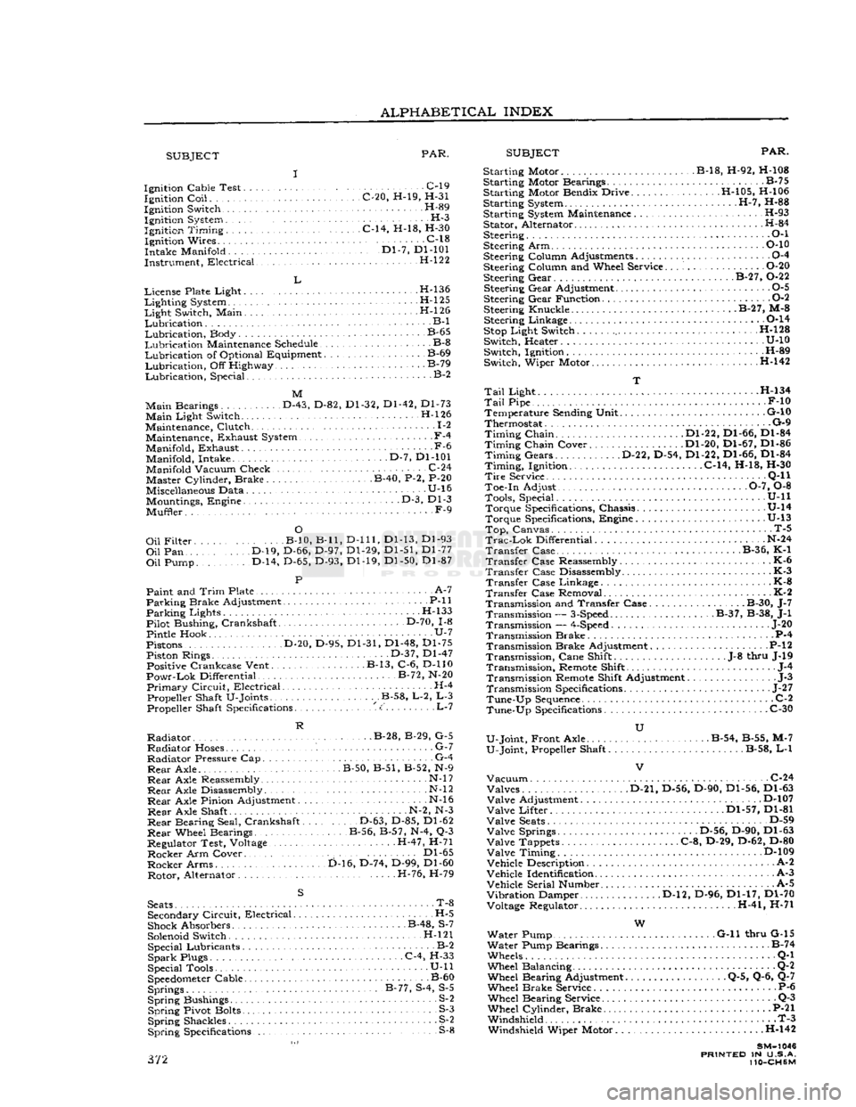
ALPHABETICAL
INDEX
SUBJECT
PAR.
SUBJECT
PAR.
Ignition Cable Test C-l9 Ignition
Coil
C-20, H-19, H-31
Ignition Switch H-89 Ignition System H-3
Ignition
Timing
C-14, H-18, H-30 Ignition Wires C-18
Intake Manifold '." Dl-7, Dl-101
Instrument, Electrical H-122
L
License Plate Light H-l36
Lighting
System H-l25
Light
Switch, Main . H-l 26
Lubrication
B-l
Lubrication,
Body B-65
Lubrication
Maintenance Schedule B-8
Lubrication
of Optional Equipment B-69
Lubrication,
Off Highway B-79
Lubrication,
Special. B-2
M
Main
Bearings D-43, D-82, Dl-32, Dl-42, Dl-73
Main
Light Switch. H-l26
Maintenance, Clutch 1-2 Maintenance, Exhaust System.,
-
F-4
Manifold, Exhaust -F-6 Manifold, Intake D-7, Dl-101
Manifold Vacuum Check. .C-24 Master Cylinder, Brake B-40, P-2, P-20
Miscellaneous Data U-16 Mountings, Engine • • •
-
D-3, Dl-3
Muffler. F-9
O
Oil
Filter B-10, B-ll,
D-lll,
Dl-13, Dl-93
Oil
Pan D-19, D-66, D-97, Dl-29, Dl-51, Dl-77
Oil
Pump. D-14, D-65, D-93, Dl-19, Dl-50, Dl-87
P
Paint and
Trim
Plate • • A-7
Parking
Brake Adjustment P-ll
Parking
Lights H-133
Pilot Bushing, Crankshaft D-70, 1-8
Pintle Hook U-7
Pistons D-20, D-95, Dl-31, Dl-48, Dl-75 Piston Rings. • • •
•
D-37, Dl-47 Positive Crankcase Vent. B-13, C-6, D-110
Powr-Lok
Differential B-72, N-20
Primary
Circuit,
Electrical H-4 Propeller Shaft U-Joints .B-58, L-2, L-3 Propeller Shaft Specifications <:' L-7
R
Radiator
B-28, B-29, G-5
Radiator
Hoses. G-7
Radiator
Pressure Cap G-4
Rear
Axle. B-50, B-51, B-52, N-9
Rear
Axle Reassembly • N-l
7
Rear
Axle Disassembly N-l
2
Rear
Axle Pinion Adjustment N-l6
Rear
Axle Shaft N-2, N-3
Rear
Bearing Seal, Crankshaft D-63, D-85, Dl-62
Rear
Wheel Bearings B-56, B-57, N-4, Q-3
Regulator Test, Voltage H-47, H-71
Rocker
Arm Cover.. . Dl-65
Rocker
Arms D-16, D-74, D-99, Dl-60 Rotor, Alternator H-76, H-79
S
Seats
• T-8 Secondary
Circuit,
Electrical H-5
Shock Absorbers B-48, S-7
Solenoid Switch. H-l21 Special Lubricants B-2
Spark
Plugs C-4, H-33
Special Tools • U-ll
Speedometer
Cable B-60 Springs B-77, S-4, S-5
Spring
Bushings S-2
Spring
Pivot Bolts S-3
Spring
Shackles S^2
Spring
Specifications S-8 372 Starting Motor B-18, H-92, H-108
Starting Motor Bearings B-75
Starting Motor Bendix Drive H-105, H-106
Starting System H-7, H-88
Starting System Maintenance H-93 Stator, Alternator H-84
Steering • • •
•
O-l
Steering Arm P-10
Steering Column Adjustments 0-4
Steering Column and Wheel Service O-20 Steering Gear. . B-27, 0-22
Steering Gear Adjustment 0-5
Steering Gear Function 0-2
Steering Knuckle. B-27, M-8 Steering Linkage 0-14
Stop
Light Switch H-128
Switch, Heater U-10 Switch, Ignition H-89
Switch, Wiper Motor H-142
T
Tail
Light . H-134
Tail
Pipe F-10 Temperature Sending Unit G-10
Thermostat G-9
Timing
Chain Dl-22, Dl-66, Dl-84
Timing
Chain Cover Dl-20, Dl-67, Dl-86
Timing
Gears D-22, D-54, Dl-22, Dl-66, Dl-84
Timing,
Ignition. C-14, H-18, H-30
Tire
Service . •
•
Q-l
1
Toe-in Adjust 0-7, 0-8 Tools, Special. . .
........
U-ll Torque Specifications, Chassis U-14
Torque Specifications, Engine .U-13
Top,
Canvas. T-5
Trac-Lok
Differential N-24
Transfer
Case B-36, K-1
Transfer
Case Reassembly K-6
Transfer
Case Disassembly K-3
Transfer
Case Linkage - K-8
Transfer
Case Removal K-2 Transmission and Transfer Case. B-30, J-7 Transmission —
3-Speed
B-37, B-38, J-l
Transmission —
4-Speed
... J-20
Transmission Brake P-4 Transmission Brake Adjustment P-l
2
Transmission,
Cane Shift .J-8 thru J-19
Transmission,
Remote Shift J-4
Transmission Remote Shift Adjustment J-3
Transmission Specifications
-
J-27
Tune-Up
Sequence
C-2
Tune-Up
Specifications C-30
U
U-Joint, Front Axle . . B-54, B-55, M-7
U-Joint, Propeller Shaft B-58, L-l
Vacuum
C-24 Valves D-21, D-56, D-90, Dl-56, Dl-63
Valve
Adjustment D-107
Valve
Lifter Dl-57, Dl-81
Valve
Seats
D-59
Valve
Springs .D-56, D-90, Dl-63
Valve
Tappets C-8, D-29, D-62, D-80
Valve
Timing D-109
Vehicle Description A-2
Vehicle Identification A-3
Vehicle Serial Number. A-5
Vibration
Damper D-l2, D-96, Dl-17, Dl-70 Voltage Regulator. H-41, H-71
W
Water Pump G-ll thru G-15
Water Pump Bearings B-74
Wheels Q-l
Wheel Balancing Q-2 Wheel Bearing Adjustment Q-5, Q-6, Q-7
Wheel Brake Service P-6 Wheel Bearing Service Q-3
Wheel Cylinder, Brake P-21 Windshield T-3 Windshield Wiper Motor . .H-142
SM-1046
PRINTED
IN U.S.A.
110-CH6M