width JEEP CJ 1953 Service Manual
[x] Cancel search | Manufacturer: JEEP, Model Year: 1953, Model line: CJ, Model: JEEP CJ 1953Pages: 376, PDF Size: 19.96 MB
Page 6 of 376
GENERAL
DATA
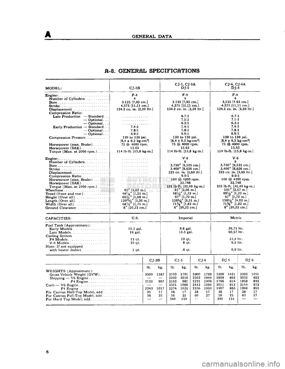
A-8. GENERAL SPECIFICATIONS
MODEL:
CJ-3B
CJ-5,
CJ-5A
DJ-5
CJ-6,
CJ-6A
DJ-6
Engine:.
Number
of
Cylinders
Bore.
.
Stroke.
Displacement
Compression
Ratio:
Late
Production —
Standard
—
Optional.
—
Optional.
Early
Production —
Standard
—
Optional.
—
Optional.
Compression
Pressure
Horsepower
(max.
Brake)
Horsepower
(SAE)
Torque
(Max. at 2000
rpm.).
. . .
Engine:
Number
of
Cylinders
Bore
Stroke
Displacement
Compression
Ratio
Horsepower
(max.
Brake).
Horsepower
(SAE)
Torque
(Max. at 2400
rpm.).
. . .
Wheelbase
Tread
(front and
rear)
,
Height
(Over
all)
Length
(Over
all).
Width
(Over
all)
Ground
Clearance
F-4
4
3.125 [7,93 cm.]
4.375 [11,11 cm.]
134.2 cu. in. [2,20 ltr.]
7.4:1 7.8:1
6.9:1
120 to 130 psi.
[8,4 a 9,2 kg-cm2] 75 <§ 4000 rpm.
15.63
114 lb-ft. [15,8 kg-m.]
80"
[2,03 m.]
487-'f6/' [1,23 m.|
6634" [1,68 m.j
129%"
[3,30 m.]
68%"
[1,75 m.] 8" [20,32 cm.]
F-4
4
3.125 [7,93 cm.]
4.375 [11,11 cm.]
134.2 cu. in. [2,20 ltr.]
6.7:1 7.1:1
6.3:1 7.4:1
7.8:1
6.9:1
120 to 130 psi.
[8,4 a 9,2 kg-cm2] 75 @ 4000 rpm. 15.63
114 lb-ft. [15,8 kg-m.]
V-6
6
3.750" [9,525 cm.]
3.400" [8,636 cm.]
225 cu.
in.
[3,69 ltr.] 9.0:1
160 @ 4200 rpm. 33.748
235 lb-ft. [32,49 kg-m.]
81"
[2,06 m.]
48K6"
[1,23 m.]
67"
[1,70 m.]
138%"
[3,51 m.]
71%"
[1,82 m.] 8" [20,32 cm.]
F-4
4
3,125 [7.93 cm.]
4.375 [11,11 cm.]
134.2 cu. in. [2,20 ltr.]
6.7:1 7.1:1
6.3:1 7.4:1
7.8:1
6.9:1
120 to 130 psi.
[8,4 a 9,2 kg-cm2] 75 @ 4000 rpm.
15.63
114 lb-ft. [15,8 kg-m.]
V-6
6
3.750" [9,525 cm.]
3.400" [8,636 cm.]
225 cu. in. [3,69 ltr.] 9.0:1
160 @, 4200 rpm. 33 748
235 lb-ft. [32,49 kg-m.]
101"
[2,57 m.]
48^6* ]1,23 m.]
67"
[1,70 m.]
1583/4" [4,02 m.]
71%"
[1,82 m.] 8" [20,32 cm.]
CAPACITIES:
U.S.
Imperial
Metric
Fuel
Tank
(Approximate):
Early
Models
Late
Models
Cooling
System
F4
Models
V-6
Models
Note: If not equipped
with
heater deduct 10.5 gal.
16 gal.
12 qt.
10 qt.
1 qt. 8.8 gal.
13.3 gal.
10 qt. 8 qt.
.8 qt. 39,75 ltr.
60,57 ltr.
11,4 ltr. 9,5 ltr.
0,9 ltr.
CJ-
3B
CJ-5
CJ-6
DJ-5
DJ
-6
lb. kg. lb.
kg. lb.
kg. lb.
kg. lb.
kg.
WEIGHTS
(Approximate):
Gross
Vehicle
Weight
(GVW).
3500
1587 3750 1701 3900 1769 3200 1451 3200 1451
Shipping
— V6
Engine
—
'—
2240 1016 2302 1044 1900 862 2033 922
F4
Engine
2132
967 2163
981 2225
1009 1796 814 1858 842
Curb
— V6
Engine
— —
2351 1066 2413 1094 2011 912 2144 972
F4
Engine
2243
1017 2274 1031
2336 1060 1907 865 1969 893
For
Canvas
Half-Top
Model, add 35
17 38
17 38
17 38
17 38 17
For
Canvas
Full-Top
Model, add 56
25 56 25 60 27 56 25 60 27
For
Hard
Top Model, add
~~
340
154 340 154 6
Page 49 of 376
'Jeep'
UNIVERSAL SERIES
SERVICE
MANUAL
D
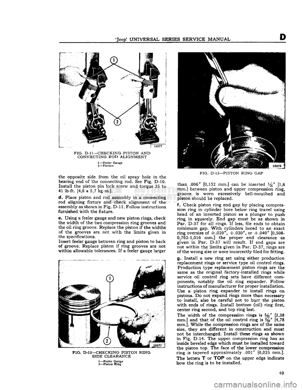
FIG.
D-ll—CHECKING PISTON
AND
CONNECTING
ROD
ALIGNMENT 1—
Feeler
Gauge
2—
Fixture
the
opposite
side from the oil spray
hole
in the
bearing
end of the connecting rod. See Fig. D-10.
Install
the piston pin lock screw and torque 35 to
41 lb-ft. [4,8 a 5,7 kg-m.].
d.
Place piston and rod assembly in a connecting
rod
aligning fixture and check alignment of the
assembly as shown in
Fig. D-ll.
Follow instructions
furnished
with the fixture.
e. Using a feeler
gauge
and new piston rings, check the width of the two compression ring
grooves
and
the oil ring groove. Replace the piston if the widths of the
grooves
are not with the limits given in
the specifications.
Insert
feeler
gauge
between
ring and piston to back
of groove. Replace piston if ring
grooves
are not
within
allowable tolerances. If a feeler
gauge
larger
FIG.
D-l 2—CHECKING PISTON RING
SIDE
CLEARANCE
1—
Feeler
Gauge
2—
Piston
Ring
FIG.
D-13—PISTON
RING
GAP
than
.006" [0,152 mm.] can be inserted
J^6"
[1,6
mm.]
between
piston and upper compression
ring,
groove
is worn excessively bell-mouthed and
piston should be replaced.
f.
Check
piston ring end gap by placing compres sion ring in cylinder bore below ring travel using head of an inverted piston as a plunger to push
ring
in squarely. End gap must be as shown in
Par.
D-37 for all rings. If less, file ends to obtain
minimum
gap.
With
cylinders bored to an exact
ring
oversize of
+.020", +.030",
or
+.040"
[0,508-
0,762-1,016
mm.] the proper end clearance as given in Par. D-37
will
result. If end
gaps
are
not within the limits given in Par.
D-3
7, rings are
of the wrong size or were incorrectly filed for fitting.
g.
Install
a new ring set using either production replacement rings or service type oil control rings.
Production
type replacement piston rings are the
same as the original factory-installed rings while
service oil control ring
sets
have different com
ponents, notably the oil ring expander. Follow
instructions of
manufacturer
for proper installation.
Use
a piston ring expander to install rings on pistons. Do not expand rings more than necessary
to install, also be careful not to
burr
the piston
with
ends of rings.
Install
bottom
(oil) ring first, center ring second, and top ring last.
The
width of the compression rings is [2,38
mm.] and that of the oil control ring is f^" [4,78
mm.].
While the compression rings are of the same
size, they are different in construction and must
not be interchanged.
Install
these
rings as shown
in
Fig. D-14. The upper compression ring has an
inside beveled
edge
which must be installed toward
the piston top. The face of the lower compression
ring
is tapered approximately .001" [0,025 mm.].
The
letters T or TOP on the upper
edge
indicate
how the ring is to be installed. 49
Page 51 of 376
![JEEP CJ 1953 Service Manual
-Jeep*
UNIVERSAL
SERIES SERVICE
MANUAL
E>
[5,928 a
5,926
cm.] for all main bearings. Allowable
taper or out-of-round of the journals is .001"
[0,0254
mm.].
D-42.
Checking Connecting Ro JEEP CJ 1953 Service Manual
-Jeep*
UNIVERSAL
SERIES SERVICE
MANUAL
E>
[5,928 a
5,926
cm.] for all main bearings. Allowable
taper or out-of-round of the journals is .001"
[0,0254
mm.].
D-42.
Checking Connecting Ro](/img/16/57040/w960_57040-50.png)
-Jeep*
UNIVERSAL
SERIES SERVICE
MANUAL
E>
[5,928 a
5,926
cm.] for all main bearings. Allowable
taper or out-of-round of the journals is .001"
[0,0254
mm.].
D-42.
Checking Connecting Rod
Crankpins
Check
the crankpin diameters with a micrometer
to ensure that they are not out-of-round or tapered more than .001"
[0,0254
mm.] The standard
crank-
pin
diameter is
1.9383*
to
1.9375"
[4,9233
a
4,9213
cm.].
D-43.
Crankshaft
Main
Bearings
The
crankshaft rotates on three main bearings
with
a running clearance of .0003" to .0029"
[0,0076
a
0,0736
mm.].
These
bearings are positioned and prevented from
rotating in their supports in the cylinder block by
dowel pins. Dowel pins are used in both the center
and
the
rear
bearing caps. No dowel pins are used
in
the front bearing cap because the bearing has
a
flange. The front main bearing takes the end
thrust
of the crankshaft. The main bearings are of premium type which provides long bearing life.
They
are replaceable and when correctly installed, provide proper clearance without filing, boring,
scraping,
or shimming. Crankshaft bearings can
be removed from this
engine
only with the
engine
out of the vehicle. Crankshaft bearings must be replaced as a complete set of three bearings, each
bearing consisting of two halves.
Main
bearings
are
available in the standard size and the following
undersizes:
.001" [0,025mm.] .012" [0,305 mm.] .002" [0,051mm.] .020" [0,508 mm.] .010" [0,254mm.] .030" [0,762 mm.]
The
.001" and .002" undersize main bearings are
for use with standard size crankshafts having
slightly worn
journals.
The .010", .020", and .030" undersize bearings are for use with undersize
crankshafts
in
those
sizes. The .012" undersize
bearings are for use with .010" undersize
crank
shafts having slightly worn journals. Bearing sizes
are
rubber stamped on the reverse side of each
bearing half.
D-44. Crankshaft
Main
Bearing Inspection
The
crankshaft
journals
must be carefully inspected
as detailed previously in Par. D-41. Worn journals
will
require undersize bearings. Scored, flaked, or
worn
bearings must be replaced. Measure the main
bearing bores in the cylinder block using a
telescope
gauge
and micrometer. Measure the bores at right
angles to the split line and at 45° to the split line.
The
bores should not be over .001"
[0,0254
mm.]
out-of-round or .001" in taper from end to end.
Also,
the bores should not be more then .001"
oversize, considering the average diameter of the
bore.
D-45.
Fitting Crankshaft
Main
Bearings
Using
Plastigage
After
wiping and carefully inspecting the bearing bore, install the proper bearing. See that the oil
hole
in the bearing upper half registers properly
with
the oil
hole
in the block, and that the bearing
lock fits properly in the notch in the block.
Install
the crankshaft if replacing bearings with the
engine
out of the vehicle. The desired running fit (dif
ference
between
the diameter of the crankshaft
journal
and the inside diameter of the fitted bear ing) for a main bearing is .0003" to .0029"
[0,0076
a
0,0736
mm.]. With a dimension in
excess
of this
standard
running fit, a satisfactory bearing replacement cannot be made and it
will
be necessary to
regrind
the crankshaft.
Install
the bearing lower
half
and the bearing cap and draw the nuts down
equally and only slightly tight. Rotate the
crank
shaft by hand to be sure it turns freely without
drag.
Pull
the nuts tighter, first one then the other,
a
little at a time, intermittently rotating the
crank
shaft by hand until the recommended torque of
35 to 45 lb-ft. [4,8 a 6,2 kg-m.] is reached. If the
bearings are of the correct size, and lubricated with
light oil before installation, the crankshaft should
turn
freely in the bearings. If the crankshaft cannot
be turned, a larger bearing is
required.
If there is no binding or tightness, it is still necessary to check
clearance to guard against too
loose
a fit. Never file
either the bearing cap or the bearing to compensate
for too much clearance. Do not use shims under a
bearing cap or behind a bearing shell. Do not run a
new bearing half with a worn bearing half. The use
of "Plastigage" of the proper size to measure .001" [0,025 mm.] clearance is recommended for check
ing crankshaft main bearing clearance. The method
of checking clearance is as follows:
a.
Remove the bearing cap and carefully wipe
all
oil from the bearing and the
journal.
b.
Lay a piece of "Plastigage" y%" [3 mm.]
shorter than the width of the bearing across the
journal
(lengthwise of the crankshaft).
c.
Install
the bearing and cap and tighten first
one nut, then the other, a little at a time to the specified torque. As the bearing
tightens
down
around
the
journal,
the "Plastigage" flattens to a
width that indicates the bearing clearance.
d.
Remove the cap and measure the width of
the flattened "Plastigage," using the scale printed
on the
edge
of the envelope. The proper size "Plasti
gage"
will
accurately measure clearance down to .001".
e. If the flattened "Plastigage" tapers toward the middle, or toward the end, or both ends, there
is a difference in clearance, indicating a taper, a
low
spot,
or other irregularity of the bearing or
journal.
D-46.
Fitting Crankshaft
Main
Bearings
Using
Shim Stock
Thin
feeler or shim stock may be used instead of "Plastigage" to check bearing clearances. The
method is simple, but care must be taken to protect
the bearing metal surface from
injury
by too much pressure against the feeler stock,
a.
Cut a piece of .001" [0,025 mm.] thick, by Yl [12,7 mm.] wide, feeler stock }4" [3 mm.]
shorter than the width of the bearing. Coat this 51
Page 56 of 376
D
HURRICANE
F4
ENGINE
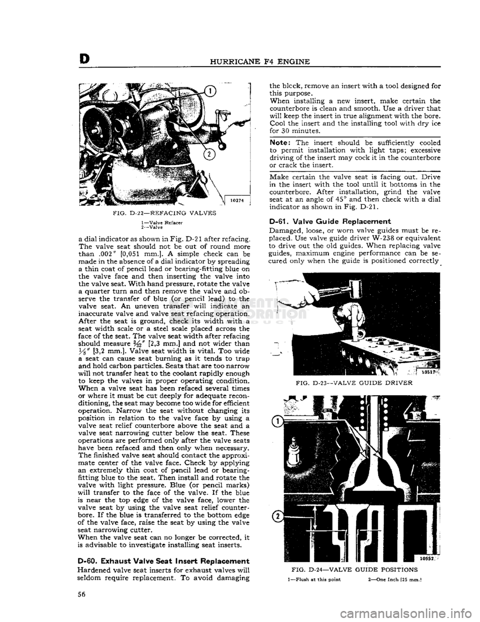
FIG.
D-2
2—REFACING
VALVES
1—
Valve
Refacer
2—
Valve
a
dial
indicator as shown in
Fig.
D-21 after refacing.
The
valve seat should not be out of round more
than
.002"
[0,051
mm.]. A simple check can be
made in the absence of a
dial
indicator by spreading
a
thin coat of pencil lead or bearing-fitting blue on
the valve face and then inserting the valve into the valve seat.
With
hand pressure, rotate the valve
a
quarter
turn
and then remove the valve and ob
serve the transfer of blue (or pencil lead) to the valve seat. An uneven transfer
will
indicate an
inaccurate
valve and valve seat refacing operation.
After
the seat is ground, check its width with a
seat width scale or a steel scale placed across the
face of the seat. The valve seat width after refacing
should measure [2,3 mm.] and not wider than
y%"
[3,2 mm.]. Valve seat width is
vital.
Too wide
a
seat can cause seat burning as it
tends
to trap
and
hold carbon particles. Seats that are too
narrow
will
not transfer heat to the coolant rapidly enough to keep the valves in proper operating condition.
When
a valve seat has been refaced several times
or
where it must be cut deeply for adequate recon
ditioning, the seat may
become
too wide for efficient
operation. Narrow the seat without changing its
position in relation to the valve face by using a
valve seat relief counterbore above the seat and a valve seat narrowing cutter below the seat. These
operations are performed only after the valve
seats
have been refaced and then only when necessary.
The
finished valve seat should contact the approximate center of the valve face.
Check
by applying
an
extremely thin coat of pencil lead or bearing-
fitting blue to the seat.
Then
install and rotate the
valve with light pressure. Blue (or pencil
marks)
will
transfer to the face of the valve. If the blue
is near the top
edge
of the valve face, lower the valve seat by using the valve seat relief counter-
bore. If the blue is transferred to the
bottom
edge
of the valve face, raise the seat by using the valve
seat narrowing cutter.
When
the valve seat can no longer be corrected, it
is advisable to investigate installing seat inserts.
D-60.
Exhaust
Valve Seat Insert Replacement
Hardened
valve seat inserts for exhaust valves
will
seldom require replacement. To avoid damaging the blcck, remove an insert with a tool designed for
this purpose.
When
installing a new insert, make certain the
counterbore is clean and smooth. Use a driver that
will
keep the insert in true alignment with the bore.
Cool
the insert and the installing tool with dry ice
for 30 minutes.
Note:
The insert should be sufficiently cooled
to permit installation with light taps; excessive
driving
of the insert may cock it in the counterbore
or
crack the insert.
Make
certain the valve seat is facing out.
Drive
in
the insert with the tool until it
bottoms
in the counterbore. After installation, grind the valve
seat at an angle of 45° and then check with a
dial
indicator
as shown in Fig. D-21.
D-61.
Valve Guide Replacement
Damaged,
loose,
or worn valve
guides
must be re
placed.
Use valve guide driver W-238 or equivalent
to drive out the old guides. When replacing valve
guides, maximum
engine
performance can be se
cured
only when the guide is positioned correctly
FIG.
D-23—VALVE
GUIDE
DRIVER
FIG.
D-24—VALVE
GUIDE
POSITIONS
1—Flush
at
this
point
2—One
Inch
[25
mm.
I
56
Page 71 of 376
'Jeep*
UNIVERSAL
SERIES
SERVICE
MANUAL
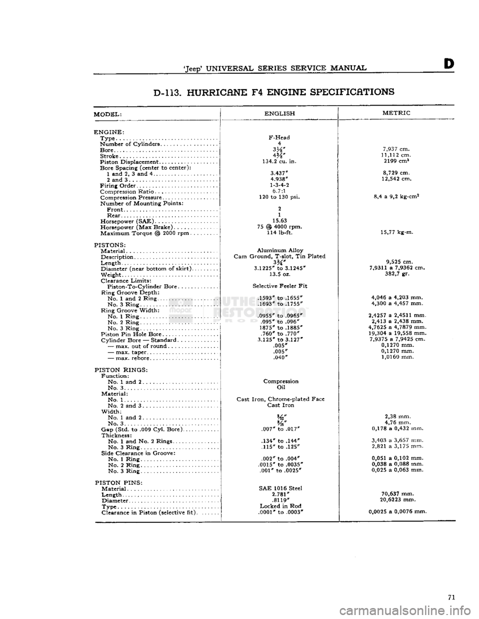
D D-l 13. HURRICANE
F4
ENGINE SPECIFICATIONS
MODEL:
ENGLISH
ENGINE:
Type
Number of Cylinders
Bore
Stroke
Piston Displacement...........
Bore
Spacing (center to center): 1 and 2, 3 and 4
2 and 3
Firing
Order Compression Ratio Compression Pressure... .
Number of Mounting Points:
Front
Rear
Horsepower (SAE)
Horsepower (Max Brake) Maximum Torque @
2000
rpm.
PISTONS:
Material
Description
Length
,.
Diameter (near
bottom
of
skirt).
Weight.
Clearance
Limits:
Piston-To-Cylindcr
Bore
Ring
Groove Depth:
No. 1 and 2 Ring No. 3 Ring
Ring
Groove Width:
No. 1 Ring No. 2 Ring
No. 3 Ring
Piston Pin Hole Bore
Cylinder
Bore — Standard.....
—
max. out of round
F-Head
4
W
134.2 cu. in.
3.437"
4.938"
1-3-4-2
6.7:1
120 to 130 psi.
2
1
15.63
@
4000
rpm. 114 lb-ft. 75
-
max. taper..
-
max. rebore.
PISTON RINGS:
Function:
No. 1 and 2 No. 3. .
Material:
No. 1. .
No. 2 and 3
Width;
No. 1 and 2
No. 3. . . .
Gap
(Std. to .009 Cyl. Bore).
Thickness:
No. 1 and No. 2 Rings....
No. 3 Ring
Side Clearance in Groove:
No. 1 Ring No. 2 Ring
No. 3 Ring
PISTON
PINS:
Material
Length
Diameter
Type
Clearance
in Piston
(selective
fit).
Aluminum
Alloy
Gam
Ground, T-slot, Tin Plated
3.1225*
to
3.1245*
13.5 oz.
Selective Feeler Fit
.1593" to .1655"
.1693" to .1755"
.0955" to .0965" .095" to .096"
1875" to .1885" .760" to .770"
3.125"
to
3.127"
.005" .005" .040"
Compression
Oil
Cast
Iron,
Chrome-plated Face
Cast
Iron
.007" to .017"
.134" to .144" .115" to .125"
.002" to .004"
.0015" to .0035" .001" to .0025"
SAE
1016 Steel
2.781"
.8119"
Locked
in Rod
.0001"
to .0003"
METRIC
7,937
cm.
11,112
cm. 2199 cm*
8,729
cm.
12,542
cm.
8,4 a 9,2 kg-cm2
15,77 kg-m.
9,525
cm.
7,9311
a
7,9362
cm.
382,7
gr.
4,046
a
4,203
mm.
4,300
a
4,457
mm.
2,4257
a
2,4511
mm. 2,413 a
2,438
mm.
4,7625
a
4,7879
mm.
19,304
a
19,558
mm.
7,9375
a
7,9425
cm.
0,1270
mm.
0,1270
mm.
1,0160
mm.
2,38 mm.
4,76 mm.
0,178 a
0,432
mm.
3,403
a
3,657
mm. 2,821 a 3,175 mm.
0,051 a 0,102 mm.
0,038
a
0,088
mm.
0,025
a
0,063
mm.
70,637
mm.
20,6223
mm.
0,0025
a
0,0076
mm. 71
Page 87 of 376
'Jeep'
UNIVERSAL
SERIES SERVICE
MANUAL
Dl
A 8
j
13415
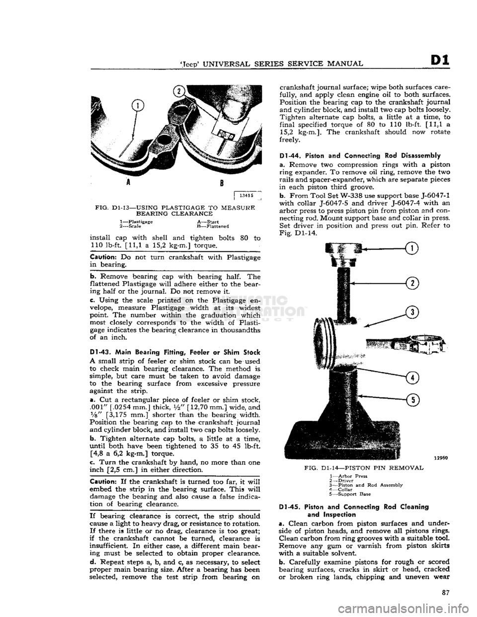
FIG.
Dl-13—USING
PLASTIGAGE
TO
MEASURE
BEARING CLEARANCE
1— Plastigage
A—Start
2—
Scale
B—Flattened
install
cap with shell and tighten
bolts
80 to 110 lb-ft. [11,1 a 15,2 kg-m.] torque.
Caution:
Do not turn crankshaft with Plastigage
in
bearing.
b.
Remove bearing cap with bearing half. The
flattened Plastigage
will
adhere either to the bear ing half or the
journal.
Do not remove it.
c. Using the scale printed on the Plastigage en
velope,
measure Plastigage width at its widest
point. The number within the graduation which
most
closely corresponds to the width of Plasti
gage
indicates the bearing clearance in thousandths
of an inch.
DI-43.
Main Bearing
Fitting,
Feeler or
Shim
Stock
A
small strip of feeler or shim stock can be used
to check main bearing clearance. The method is
simple, but care must be taken to avoid damage
to the bearing surface from excessive pressure against the strip.
a.
Cut a rectangular piece of feeler or shim stock, .001"
[.0254
mm.] thick,
i/2"
[12,70
mm.] wide, and
Vs"
[3,175 mm.] shorter than the bearing width.
Position the bearing cap to the crankshaft journal
and
cylinder block, and install two cap
bolts
loosely.
b.
Tighten alternate cap bolts, a little at a time,
until
both have
been
tightened to 35 to 45 lb-ft. [4,8 a 6,2 kg-m.] torque.
c.
Turn
the crankshaft by hand, no more than one
inch
[2,5 cm.] in either direction.
Caution:
If the crankshaft is turned too far, it
will
embed the strip in the bearing surface.
This
will
damage the bearing and also cause a false indication of bearing clearance.
If
bearing clearance is correct, the strip should cause a light to heavy drag, or resistance to rotation.
If
there is little or no drag, clearance is too great;
if
the crankshaft cannot be turned, clearance is
insufficient. In either case, a different main bear ing must be
selected
to obtain proper clearance.
d.
Repeat
steps
a, b, and c, as necessary, to
select
proper main bearing size. After a bearing has
been
selected, remove the
test
strip from bearing on
crankshaft
journal surface; wipe both surfaces care
fully,
and apply clean
engine
oil to both surfaces. Position the bearing cap to the crankshaft journal
and
cylinder block, and install two cap
bolts
loosely.
Tighten
alternate cap bolts, a little at a time, to
final
specified torque of 80 to 110 lb-ft. [11,1 a 15,2 kg-m.]. The crankshaft should now rotate
freely.
Dl-44.
Piston
and
Connecting
Rod
Disassembly
a.
Remove two compression rings with a piston
ring
expander. To remove oil ring, remove the two
rails
and spacer-expander, which are separate
pieces
in
each piston third
groove.
b.
From
Tool Set W-338 use support base J-6047-1
with collar J-6047-5 and driver J-6047-4 with an
arbor
press to press piston pin from piston and con
necting rod. Mount support base and collar in press. Set driver in position and press out pin. Refer to
Fig.
Dl-14.
FIG.
Dl-14—PISTON
PIN
REMOVAL
1—
Arbor
Press
2—
Driver
3—
Piston
and Rod Assembly
4—
Collar
•
5—Support Base Dl-45.
Piston
and
Connecting
Rod
Cleaning
and Inspection
a.
Clean
carbon from piston surfaces and under
side of piston heads, and remove all pistons rings.
Clean
carbon from ring
grooves
with a suitable tool.
Remove any gum or varnish from piston skirts with a suitable solvent.
b.
Carefully examine pistons for rough or scored
bearing surfaces, cracks in
skirt
or head, cracked
or
broken ring lands, chipping and uneven wear 87
Page 88 of 376
Pi
DAUNTLESS
¥-6
ENGINE
which
would cause rings to seat improperly or have
excessive clearance in
ring
grooves. Damaged or
faulty
pistons should be replaced,
c.
Inspect bearing surfaces of piston pins and check
for
wear by measuring worn and unworn surfaces
with
a micrometer. Rough or worn pins should be
replaced.
Test fit the piston pins in piston
bosses.
Occasionally,
a pin
will
be tight due to gum or
varnish
deposits.
This
may be corrected by remov
ing
the deposit with a suitable solvent. If piston
bosses
are worn out-of-round or oversize, the piston
and
pin assembly must be replaced. Oversize pins
are
not
practical,
since the pin must be a press fit
in
the connecting rod bore. Piston pins must fit the
piston with an easy finger push at
70°F.
[21°C.].
They
should have .0004" to .0007"
[0,0178
a
0,0102
mm.] clearance.
Dl-46.
Piston Fitting
If
cylinder bores are rebored or heavily honed,
new and possibly oversize diameter pistons must be
installed.
A new piston must be fitted to its cylinder
bore.
A satisfactory method of fitting pistons is as
follows.
a.
Expand
a
telescope
gauge
to fit the cylinder bore at right angles to the piston pin and
between
1
Vi"
to 2" [3,7 a 5,1 cm.] from the top.
b.
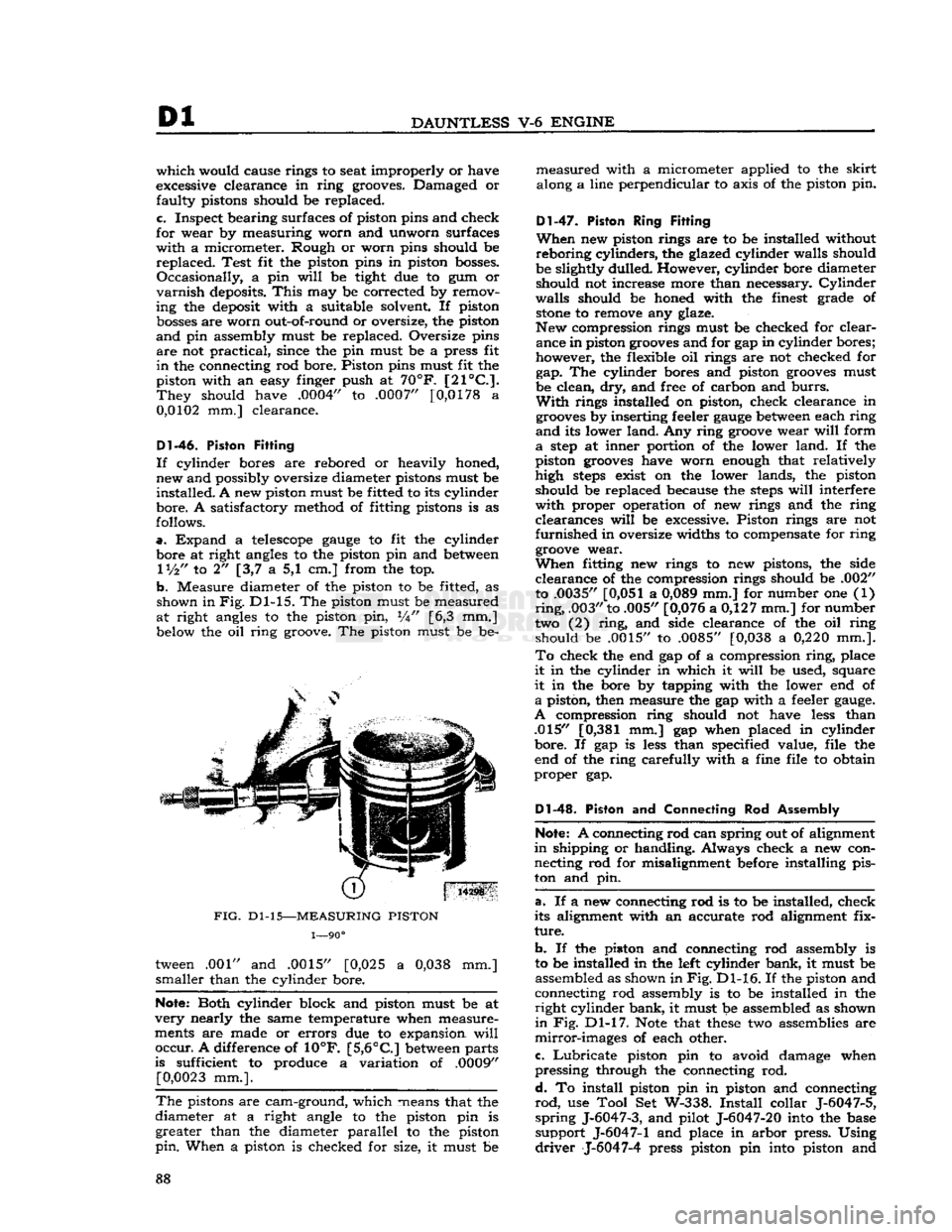
Measure diameter of the piston to be fitted, as
shown in
Fig.
Dl-15. The piston must be measured
at
right angles to the piston pin, W [6,3 mm.] below the oil
ring
groove. The piston must be be-
FIG.
Dl-15—MEASURING
PISTON
1—90°
tween .001" and .0015" [0,025 a
0,038
mm.]
smaller
than the cylinder bore.
Note:
Both cylinder block and piston must be at
very
nearly the same temperature when measure
ments are made or
errors
due to expansion
will
occur.
A difference of 10°F.
[5,6°C]
between
parts
is sufficient to produce a variation of .0009"
[0,0023
mm.].
The
pistons are cam-ground, which means that the
diameter at a right angle to the piston pin is
greater
than the diameter
parallel
to the piston
pin.
When a piston is checked for size, it must be
measured
with a micrometer applied to the
skirt
along a line
perpendicular
to axis of the piston pin.
Dl-47.
Piston Ring Fitting
When
new piston rings are to be installed without
reboring
cylinders,
the glazed cylinder walls should
be slightly dulled. However, cylinder bore diameter
should
not increase more than necessary.
Cylinder
walls
should be honed with the finest grade of
stone
to remove any glaze.
New compression rings must be checked for clear ance in piston
grooves
and for gap in cylinder bores;
however, the flexible oil rings are not checked for gap. The cylinder bores and piston
grooves
must
be clean, dry, and free of carbon and
burrs.
With
rings installed on piston, check clearance in
grooves
by inserting feeler
gauge
between
each
ring
and
its lower
land.
Any
ring
groove
wear
will
form
a
step
at inner portion of the lower
land.
If the
piston
grooves
have worn enough that relatively
high
steps
exist on the lower lands, the piston
should
be replaced because the
steps
will
interfere
with
proper operation of new rings and the
ring
clearances
will
be excessive. Piston rings are not
furnished
in oversize widths to compensate for
ring
groove
wear.
When
fitting new rings to new pistons, the side
clearance
of the compression rings should be .002" to .0035"
[0,051
a
0,089
mm.] for number one (1)
ring,
.003" to .005" [0,076 a 0,127 mm.] for number
two (2)
ring,
and side clearance of the oil
ring
should
be .0015" to .0085" [0,038 a
0,220
mm.].
To
check the end gap of a compression
ring,
place
it
in the cylinder in which it
will
be used, square
it
in the bore by tapping with the lower end of
a
piston, then measure the gap with a feeler
gauge.
A
compression
ring
should not have
less
than .015"
[0,381
mm.] gap when placed in cylinder
bore.
If gap is
less
than specified value, file the
end of the
ring
carefully with a fine file to obtain
proper
gap.
Dl-48.
Piston and Connecting Rod Assembly
Note:
A connecting rod can spring out of alignment
in
shipping or handling. Always check a new con
necting rod for misalignment before installing pis
ton and pin.
a.
If a new connecting rod is to be installed, check
its alignment with an accurate rod alignment fix
ture.
b.
If the piston and connecting rod assembly is
to be installed in the left cylinder bank, it must be assembled as shown in
Fig.
Dl-16. If the piston and
connecting rod assembly is to be installed in the
right
cylinder bank, it must be assembled as shown
in
Fig. Dl-17.
Note
that
these
two assemblies are
mirror-images
of each other.
c.
Lubricate
piston pin to avoid damage when
pressing
through the connecting rod.
d.
To install piston pin in piston and connecting
rod,
use
Tool
Set W-338.
Install
collar J-6047-5,
spring
J-6047-3, and pilot J-6047-20 into the base
support
J-6047-1 and place in
arbor
press. Using
driver
J-6047-4 press piston pin into piston and 88
Page 94 of 376
Dl
DAUNTLESS
V-6
ENGINE
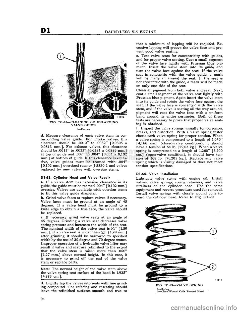
FIG.
D1-28—CLEANING
OR
ENLARGING
VALVE
GUIDE
1—Reamer
d.
Measure clearance of each valve stem in cor
responding valve guide. For intake valves, this
clearance
should be .0012" to .0032" [0,0305 a
0,0813
mm.]. For exhaust valves, this clearance should be .0015" to .0035"
[0,0381
a
0,0889
mm.]
at top of guide and .002" to .004"
[0,051
a 0,102 mm.] at bottom of guide. If this clearance is exces
sive, valve guides must be reamed with .004" [0,102 mm.] oversized reamer J-5830-1 and valves
replaced
by new valves with oversize stems.
Dl-63.
Cylinder
Head
and Valve
Repair
a.
If a valve stem has excessive clearance in its
guide, the guide must be reamed .004" [0,102 mm.]
oversize. Valves are available with oversize stems
to fit this valve guide diameter.
b.
Grind
valve faces or replace valves if necessary.
Valve
faces must be ground at an angle of 45 degrees. If a valve head must be ground to a
knife
edge
to obtain a true face, the valve should
be replaced.
c.
If necessary, grind valve seats at an angle of 45 degrees.
Grinding
a valve seat decreases valve
spring
pressure and increases the width of the seat.
The
nominal width of the valve seat is
[
1,59
mm.].
If a valve seat is wider than %" [1,98 mm.]
after grinding, it should be narrowed to specified
width
by the use of 20-degree and 70-degree stones.
Improper
operation of a hydraulic valve lifter may
result
if valve and seat are refinished to the extent
that the valve stem is raised more than .050" [1,27 mm.] above normal height. In this case, it
is necessary to grind off the end of the valve stetti or replace parts.
Note:
The normal height of the valve stem above
the valve spring seat surface of the head is
1.925"
[4,889 cm.].
d.
Lightly
lap the valves into seats with fine grind
ing compound. The refacing and reseating should
leave the refinished surfaces smooth and true so that a minimum of lapping
will
be required. Ex
cessive lapping
will
groove the valve face and pre
vent
good
valve seating.
e. Test valve seats for concentricity with guides,
and
for proper valve seating. Coat a small segment
of the valve face lightly with Prussian blue pig ment.. Insert the valve stem into its guide and
turn
the valve face against the seat. If the valve seat is concentric with the valve guide, a
mark
will
be made all around the seat. If the seat is not concentric with the guide, a
mark
will
be made
on only one side of the seat.
Clean
all pigment from both valve and seat. .Next,
coat a small segment of the valve seat lightly with
Prussian
blue pigment. Again insert the valve stem into its guide and rotate the valve face against the
seat. If the valve face is concentric with the valve
stem, and if the valve is seating all the way around,
pigment
will
coat the valve face with a uniform
band
around its entire perimeter. Both of
these
tests
are necessary to prove that proper valve seat
ing is obtained.
f. Inspect the valve springs visually for corrosion,
breaks,
and distortion.
With
a valve spring tester
check
each valve spring for proper tension. When
a
valve spring is compressed to a length of
1.640"
[4,166 cm.] (closed-valve condition), it should
have a tension of 64 lb. [29,03 kg.]. When a valve
spring
is compressed to a length of
1.260"
[3,200
cm.] (open-valve condition), it should have ten sion of 168 lb. [76,205 kg.]. Replace any valve
spring
which is visibly damaged or
does
not
meet
tension specifications.
Dl-64.
Valve Installation
Lubricate
valve stems with engine oil.
Install
valves, valve springs, spring retainers, and valve
retainers
on the cylinder head. Use the same equipment and reverse procedure used for removal.
Install
valve springs with closely wound coils to
ward
the cylinder head. Refer to Fig. Dl-29.
FIG.
Dl-29—VALVE
SPRING
1—
Spring
2—
Close
Wound
Coils
Toward
Head
94
Page 106 of 376
Dl
DAUNTLESS
V-6
ENGINE
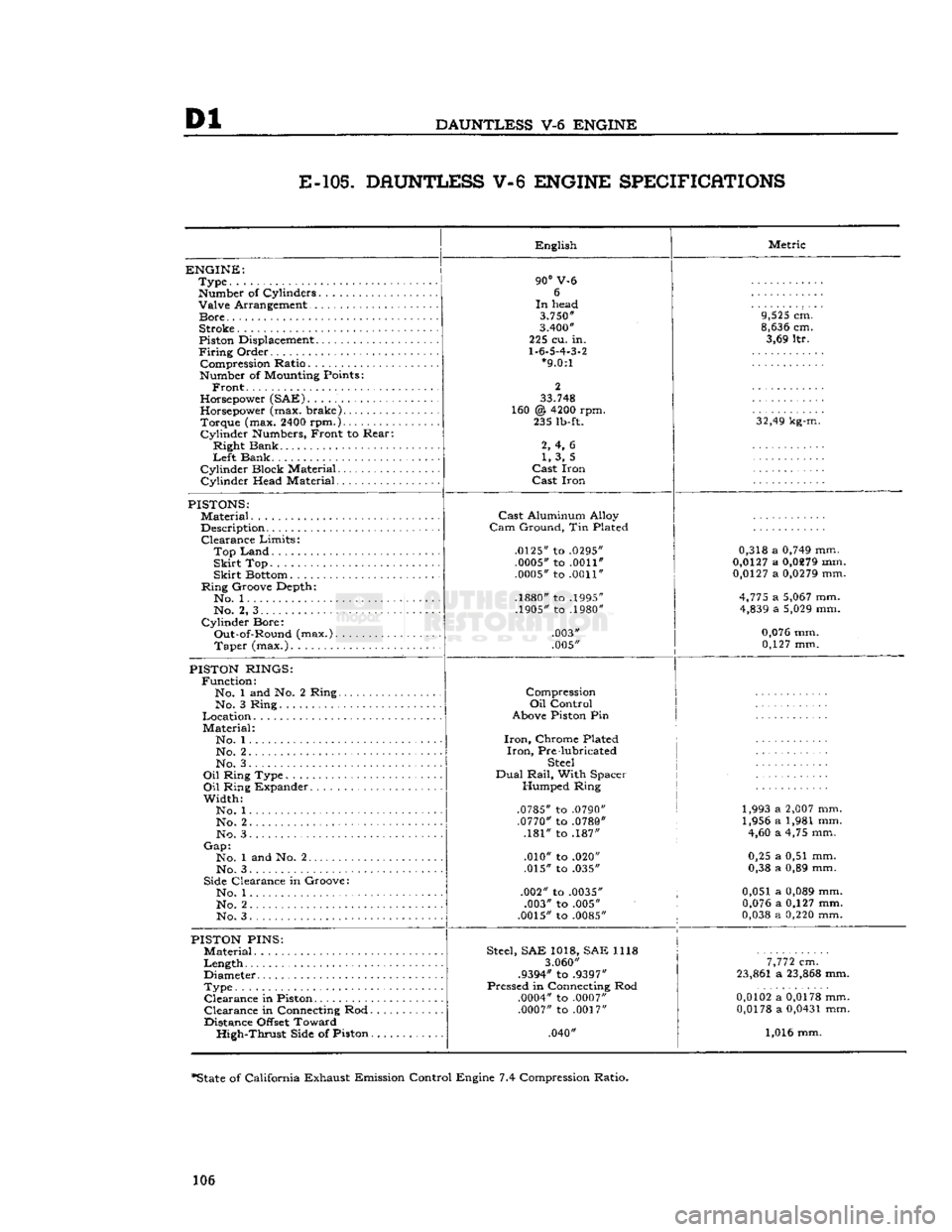
E-105.
DAUNTLESS V-6 ENGINE SPECIFICATIONS
ENGINE:
Type
Number
of Cylinders Valve Arrangement
Bore
Stroke
Piston
Displacement
Firing
Order Compression Ratio
Number
of
Mounting
Points:
Front.
Horsepower
(SAE)
Horsepower
(max. brake) Torque (max.
2400
rpm.)
Cylinder
Numbers,
Front to Rear:
Right Bank
Left
Bank
Cylinder Block Material
Cylinder Head Material English
90°
V-6 6
In
head
3.750"
3.400"
225 cu. in.
1.6.5.4.3.2
*9.0:1
2
33.748
160 @
4200
rpm. 235
lb-ft.
2, 4, 6 1, 3, 5
Cast
Iron
Cast
Iron Metric
9,525
cm.
8,636
cm. 3,69 ltr.
32,49
kg-m.
PISTONS:
Material
Description Clearance Limits:
Top
Land
Skirt
Top
Skirt
Bottom
Ring Groove Depth*. No. 1
No. 2, 3
Cylinder Bore: Out-of-Round (max.). Taper (max.)
Cast
Aluminum Alloy
Cam
Ground, Tin Plated
.0125"
to
.0295" .0005"
to
.0011"
.0005"
to
.0011"
.1880"
to
.1995"
.1905"
to
.1980"
.003"
.005" 0,318 a
0,749
mm.
0,0127
a
0,0279
mm.
0,0127
a
0,0279
mm.
4,775
a
5,067
mm.
4,839
a
5,029
mm.
0,076
mm. 0,127 mm.
PISTON
RINGS:
Function: No. 1 and No. 2 Ring.. No. 3 Ring
Location
Material: No. 1...
No. 2 No. 3.
Oil
Ring Type
Oil
Ring Expander
Width: No. 1
No. 2. .
No. 3
Gap:
No. 1 and No. 2
No. 3
Side
Clearance in Groove: No. 1
No. 2
No. 3 Compression
Oil
Control
Above
Piston
Pin
Iron,
Chrome Plated
Iron,
Pre lubricated
Steel
Dual
Rail,
With Spacer Humped Ring
.0785"
to
.0790" .0770"
to
.0780"
.181" to .187"
.010" to .020"
.015" to .035"
.002" to
.0035"
.003" to .005"
.0015"
to
.0085"
1,993 a
2,007
mm.
1,956 a 1,981 mm. 4,60 a 4,75 mm.
0,25 a 0,51 mm.
0,38 a 0,89 mm.
0,051 a
0,089
mm.
0,076
a 0,127 mm.
0,038
a
0,220
mm.
PISTON
PINS:
Material
Length
Diameter
Type Clearance in
Piston
Clearance in
Connecting
Rod.
Distance
Offset
Toward High-Thrust
Side
of Piston.
Steel,
SAE 1018, SAE 1118
3.060"
.9394"
to
.9397"
Pressed in
Connecting
Rod
.0004"
to
.0007" .0007"
to
.0017"
.040"
7,772
cm.
23,861
a
23,868
mm.
0,0102
a
0,0178
mm.
0,0178
a
0,0431
mm.
1,016 mm.
*State
of California Exhaust Emission Control Engine 7.4 Compression Ratio.
106
Page 170 of 376
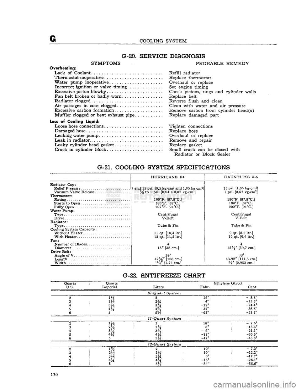
G
COOLING SYSTEM G-20.
SERVICE DIAGNOSIS
SYMPTOMS
PROBABLE REMEDY
Overheating:
Lack
of Coolant Refill radiator
Thermostat inoperative . Replace thermostat
Water
pump inoperative. Overhaul or replace
Incorrect
ignition or valve timing. Set
engine
timing
Excessive piston blowby Check pistons, rings and cylinder walls
Fan
belt
broken or badly worn Replace
belt
Radiator
clogged
Reverse flush and clean
Air
passages
in core
clogged
Clean with water and air pressure
Excessive carbon formation. Remove carbon from cylinder head(s) Muffler
clogged
or
bent
exhaust
pipe
Replace damaged part
Loss
of Cooling
Liquid:
Loose
hose
connections
Tighten
connections
Damaged
hose
Replace
hose
Leaking
water pump Overhaul or replace
Leak
in radiator Remove and repair
Leaky
cylinder head
gasket
Replace
gasket
Crack
in cylinder block. Small crack can be closed with
Radiator
or Block Sealer
G-21. COOLING SYSTEM SPECIFICATIONS
Radiator
Cap:
Relief
Pressure
Vacuum
Valve Release.
Thermostat:
Rating
Starts to Open
Fully
Open
Water
Pump:
Type.
Drive
Radiator:
Type
Cooling System Capacity: Without Heater
With
Heater..
Fan:
Number of Blades Diameter
Drive
Belt: Angle of V
Length
Width
HURRICANE
F4
7 and 15 psi. [0,5 kg-cm2 and 1,05 kg cm2]
lA to 1 psi. [0,04 a 0,07 kg-cm2]
190°F.
[87,8°C]
180°F.
[82°C]
202°F.
[94°C]
Centrifugal
V-Belt
Tube
8s Fin
11 qt. [10,4 ltr.] 12 qt. [11,5 ltr.]
15" [38 cm.]
38°
42%" [108 cm.] [1,74 cmJ
DAUNTLESS
V-6 15 psi. [1,05 kg-cm2]
1 psi. [0,07 kg-cm2]
190°F.
[87,8°C]
180°F.
[82°C]
202°F.
[94°C]
Centrifugal
V-Belt
Tube
& Fin
9 qt. [8.5 ltr.]
10 qt. [9,4 ltr.]
4
\SbA"
[39,7 cm.]
38°
43.92"
[111,5
cm.] Vg"
[0.952
cm.] G-22. ANTIFREEZE CHERT
Quarts
i
Quarts
Ethylene Glycol
U.S.
Imperial
Liters
Fahr.
Cent.
10-Quart
System
2
m
2
16°
-
8.8°
3
2V2
2%
4°
-15.5°
4
3H
-12°
-24.4°
5 4M -34°
-36.6°
6
5
5Vs
-62°
-52.2°
11-Quart
System
2 2
18° -
7.6°
3 2H
2%
8°
-13.3°
4
3%
-
6°
:
-21.10
5 4M 4M -23°
-30.5°
6
5
SVs
-47°
-43.8°
12-Quart
System
2
1 m 2 1
19° ;
- 7.2°
3
2*A
10°
!
-12.2°
4
I
3H
3M 0°
;
-17.7°
5 !
4M 4^ :
-15°
s
-26.1°
6 1 5
5%
-34°
-36.6°
170