tire type JEEP CJ 1953 User Guide
[x] Cancel search | Manufacturer: JEEP, Model Year: 1953, Model line: CJ, Model: JEEP CJ 1953Pages: 376, PDF Size: 19.96 MB
Page 302 of 376
N
REAR
AXLE a.
Place the transmission in neutral.
b.
Raise one wheel off the floor and place a block
in
front and at the
rear
of the
opposite
wheel.
c.
Apply a torque wrench to the axle shaft nut of
the elevated wheel.
d.
Turn
wheel with torque wrench. Disregard
breakaway
torque and observe torque required to
continuously
turn
wheel smoothly. Torque should
read
40 lb-ft [5,53 kg-m.] or more.
N-23. Powr-Lok
Differential Disassembly
/
and Reassembly
Refer
to
Figs.
N-38 and N-39.
The
procedure for overhauling disc type
Powr-Lok
differentials is as follows:
a.
Remove axle shafts following procedure de
scribed
in Par. N-2.
b.
Remove housing cover and gasket.
c.
Remove the
Powr-Lok
differential from the axle.
Do not remove the ring gear or bearing
cone
and
rollers
unless replacement is to be made.
Mark
the hearing cups so they may later be reassembled
with
the same bearing cones.
Mark
the differential
case halves for correct alignment at reassembly.
Each
pinion mate cross shaft should also be marked
so that each pin cam surface
will
match with the
same
V-ramp
in the case when reassembled.
d.
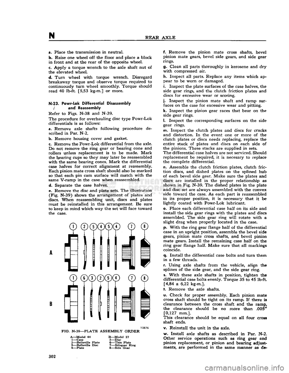
Separate the case halves. e. Remove the disc and plate
sets.
The illustration
(Fig.
N-39) shows the arrangement of plates and
discs.
When reassembling unit, discs and plates must be reinstalled in this arrangement. Be sure
to keep in mind which way the set
will
face toward the case.
^®(j)(j)CD©
® /'Ml
I
11
11 v
FIG.
N-39—PLATE
ASSEMBLY
ORPER
A—Model
44
B—Model
27 1—
Case
5—Disc
2—
Belleville
Plate
6—Thin
Plate
3—
Belleville
Disc
7—Sidegear
Ring
4—Plate
8—Side
Gear
f. Remove the pinion mate cross shafts, bevel
pinion mate gears, bevel side gears, and side gear
rings.
g.
Clean
all parts thoroughly in kerosene and dry
with
compressed air.
h.
Inspect all parts. Replace any items which ap
pear
to be worn or damaged.
i.
Inspect the plate surfaces of the case halves, the
side gear rings, and the clutch friction plates and
discs for excessive wear or scoring.
j.
Inspect the pinion mate shaft and ramp
sur
faces on the case for excessive wear and pitting,
k.
Inspect the pinion gear races that bear on the
side gear rings.
I.
Inspect the corresponding surfaces on the side
gear rings.
m.
Inspect the clutch plates and discs for cracks
and
distortion. In the
event
one or more of the
clutch
plates or discs
needs
replacing, replace the
entire stack of plates and discs on each side of
the pinions. These stacks are supplied in
sets.
The
differential case halves are not serviced. Should replacement be required, it is necesary to replace
the complete differential.
n.
Assemble the clutch friction plates, clutch
fric
tion discs, and dished plates on the splined hub of each bevel side gear. Make sure the plates and
discs are installed in the proper relationship as shown in Fig. N-39. The dished plates in the plate
and
disc set are always assembled with the convex
side toward the case. As each part is reassembled
in
its proper position, it is necessary that it be lightly coated with
Powr-Lok
lubricant,
o.
Place each differential case
half
on its side and
install
the side gear rings with the plates and discs
assembled. The side gear ring
will
rotate with a slight drag when properly located in the case,
p.
With
the ring gear flange
half
of the differential
case in an upright position, assemble the bevel side gears, pinion mate cross shafts, and bevel pinion
mate gears.
Install
the remaining case
half
on the
ring
gear flange half. Make sure that all markings
coincide.
q.
Install
the differential case
bolts
and
turn
them
in
a few threads.
r.
Using axle shafts from the vehicle, align the
splines of the side gear, and the side gear
ring,
s.
With
these
axle shafts in position, tighten the
differential
case
bolts
evenly. Torque 35 to 45 lb-ft. [4,84 a 6,22 kg-m.].
t. Remove the axle shafts.
u.
Check
for proper assembly.
Each
pinion mate
cross shaft should be tight on its
ramp.
If there is
clearance
between
the cross shaft and the
ramp,
the clearance should be no more than .005" [0,127 mm.].
This
clearance should be equal on all four cross
shaft ends.
v. Reinstall the unit in the axle.
w.
Install
axle shafts as described in Par. N-2.
Other
service operations such as ring gear and
pinion replacement, or pinion and bearing adjust ments, are performed in the same manner as de- 302
Page 324 of 376
p
BRAKES
13264
FIG- P-2—DOUBLE
SAFETY BRAKE
MASTER
CYLINDER
With
the Double-Safety brake system type master
cylinder,
failure
in one part of the brake system
does
not result in
failure
of the entire hydraulic
brake system. Failure in the
front
brake system
will
leave the rear brake system
still
operative or
failure
in
the rear system
will
leave the
front
brake system
operative.
A
double hydraulic
cylinder
with
two outlets, two
residual
check valves, two
fluid
reservoirs, and
two
hydraulic pistons (a
primary
and secondary)
are operated in tandem by a single hydraulic push
rod.
The
primary
outlet is connected to the
front
brakes
with
the secondary outlet connected to the rear brakes.
With
the master
cylinder
fluid
reservoirs
filled
and the
front
and rear brake system
bled,
there is a
solid
column
of
fluid
on the
forward
side of both the
primary
and the secondary pistons.
Upon
application
of the brakes, through movement
of
the brake pedal,
fluid
is displaced by the pistons
into
the wheel cylinders to activate both
front
and
rear brakes.
Upon
release
of the brakes,
fluid
re
turns
from
the rear wheel cylinders through the secondary residual check valve to the secondary
portion
of the master
cylinder
bore.
Fluid
also
returns
from
the
front
wheel cylinders through the
primary
residual check valve to the
primary
portion
of the master
cylinder
bore.
P-3.
Parking
Brakes
— DJ-5, DJ-6
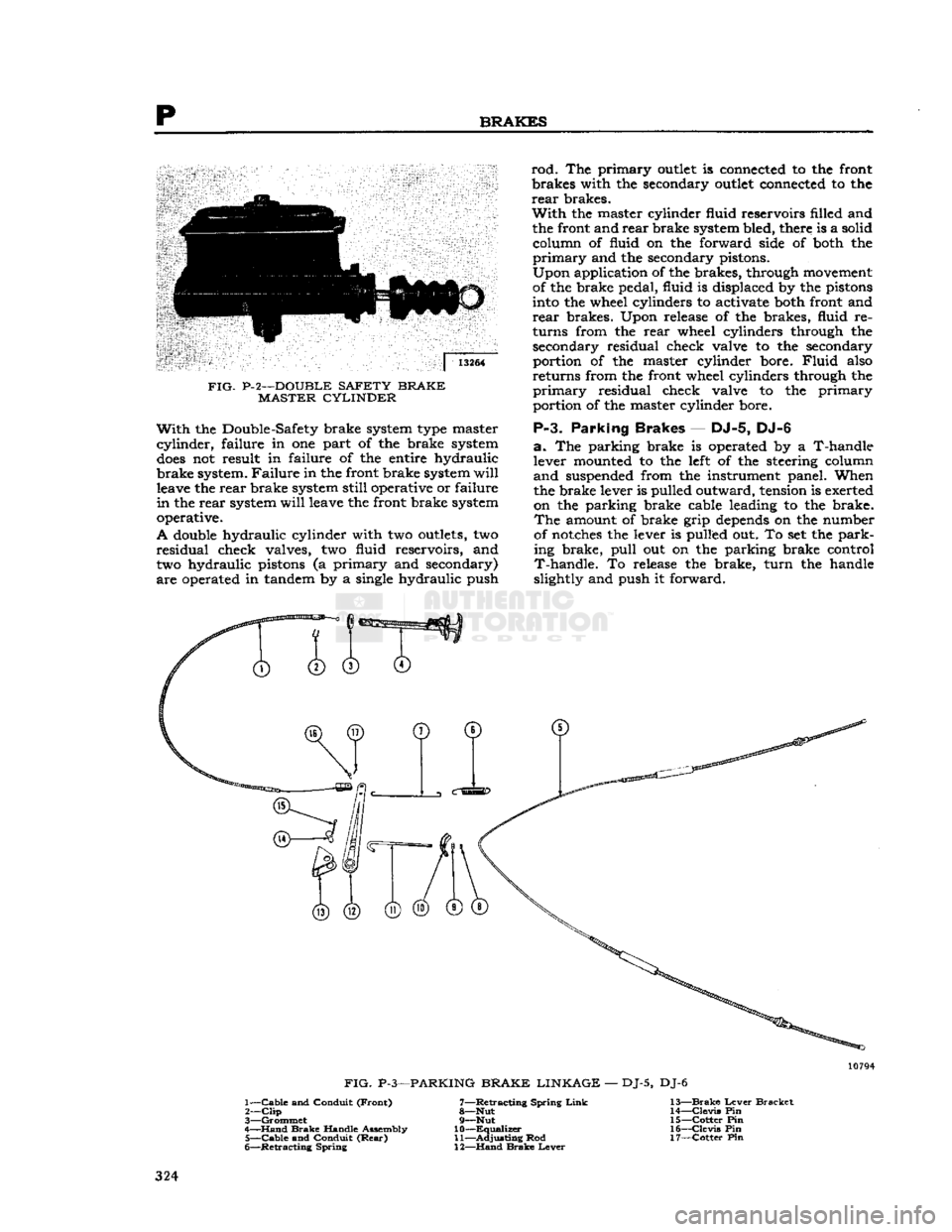
a.
The parking brake is operated by a T-handle
lever
mounted to the
left
of the steering
column
and
suspended
from
the instrument panel. When
the brake lever is
pulled
outward, tension is exerted
on
the parking brake cable leading to the brake.
The
amount of brake
grip
depends
on the number
of
notches the lever is
pulled
out. To set the park
ing
brake,
pull
out on the parking brake
control
T-handle.
To
release
the brake,
turn
the handle
slightly
and push it
forward.
0
FIG.
P-3—PARKING
BRAKE LINKAGE
—
DJ-5,
DJ-6
1—
Cable
and
Conduit
(Front)
7—Retracting
Spring
Link
13—Brake
Lever
Bracket
2—
Clip
8—Nut
14—Clevis
Pin
3—
Grommet
9—Nut
15—Cotter
Pin
4—
Hand
Brake
Handle
Assembly
10—Equalizer
16—Clevis
Pin
5—
Cable
and
Conduit
(Rear)
11—Adjusting
Rod
17—Cotter
Pin
6—
Retracting
Spring
12—Hand
Brake
Lever
324
Page 326 of 376
p
BRAKES
be either a defective master cylinder or the use of
low grade brake fluid which has expanded because
of heat. Use standard duty brake fluid conforming to
SAE-J1703
specification.
P-7.
Bleeding
Brakes
The
hydraulic
brake system must be bled whenever
a
fluid line has been disconnected or air
gets
into the system. A leak in the system may sometimes
be indicated by the presence of a spongy brake
pedal.
Air trapped in the system is compressible
and
does
not permit the pressure, applied to the
brake
pedal, to be transmitted solidly through to
the brakes. The system must be absolutely free
from
air at all times. When bleeding brakes, bleed
at that wheel with the
longest
line from the master
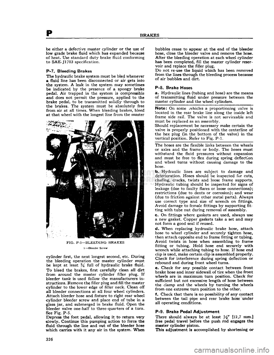
FIG.
P-5—BLEEDING
BRAKES
1—Bleeder
Screw
cylinder
first, the next
longest
second, etc. During
the bleeding operation the master cylinder must
be kept at least %
full
of hydraulic brake fluid.
To
bleed the brakes, first carefully clean all
dirt
from
around the master cylinder filler plug. If
bleeder tank is used follow the manufacturers in
structions.
Remove the filler plug and
fill
the master
cylinder
to the lower
edge
of filler neck.
Clean
off
all
bleeder connections at all four wheel cylinders.
Attach
bleeder
hose
and fixture to right
rear
wheel
cylinder
bleeder screw and place end of tube in a
glass jar, and submerged in brake fluid. Open the bleeder valve one-half to three-quarters of a
turn.
See
Fig.
P-5.
Depress the
foot
pedal, allowing it to return very
slowly. Continue this pumping action to force the
fluid
through the line and out of the bleeder
hose
which
carries with it any air in the system. When bubbles cease to appear at the end of the bleeder
hose, close the bleeder valve and remove the hose.
After
the bleeding operation at each wheel cylinder
has been completed,
fill
the master cylinder reser
voir
and replace the filler plug.
Do not re-use the liquid which has been removed
from
the lines through the bleeding process because
of air bubbles and
dirt.
P-8.
Brake Hoses
a.
Hydraulic
lines (tubing and hose) are the means
of transmitting fluid under pressure between the master cylinder and the wheel cylinders.
Note:
On
some
vehicles a proportioning valve is
located in the
rear
brake line along the inside left
frame
side
rail.
The valve is not serviceable and
must be replaced as an assembly.
Should
replacement be necessary make certain the valve is properly positioned with the centerline of
the hex plug (in the bottom of the valve) in the
vertical
position. Refer to Fig. P-l.
The
hoses
are the flexible links between the wheels
or
axles and the frame or body. The
hoses
must
withstand
the fluid pressures without expansion
and
must be free to flex during spring deflection
and
wheel turns without causing damage to the
hose.
b.
Hydraulic
lines are subject to damage and
deterioration. Hoses should be inspected for cuts,
chafing,
cracks,
twists and
loose
frame supports.
Hydraulic
tubing should be inspected for signs of
leakage (due to faulty flares or
loose
connections);
restrictions
(due to dents or corrosion); and wear (due to friction against other metal parts). Always
use correct type and size of wrench on fittings.
Avoid
damage to female fittings by supporting fit
ting with tube nut during removal of assembly.
c.
On fittings where gaskets are used, always use
a
new gasket. Copper gaskets take a set and may
not form a
good
seal if reused.
d.
When replacing hydraulic brake hose, attach
hose
to wheel cylinder and securely tighten hose,
then attach
opposite
end to frame fitting or tubing.
Avoid
twists in
hose
when assembling to frame fitting
or
tubing. Hold
hose
end securely with
wrench
while attaching tubing to hose. If
hose
end
clip
is used, make certain clip is assembled properly.
Check
for interference during spring deflection or
rebound and during front wheel turns.
e.
Check
for any possible contact between front
brake
hose
and inner sidewall of tire when the front
wheels are in maximum
turn
position.
Check
for sufficient but not excessive length of
hose
between
the clamp and the wheels by turning the wheels
from
one extreme
turn
position to the otherl
f.
Check
that there is no possibility of any contact between the
tail
pipe and
rear
brake
hose
under
all
operating conditions.
P-9.
Brake Pedal Adjustment
There
should always be at least W [12,7 mm.]
free pedal travel before the push rod
engages
the master cylinder piston.
This
adjustment is accomplished by shortening or 326
Page 337 of 376
'Jeep'
UNIVERSAL
SERIES SERVICE
MANUAL
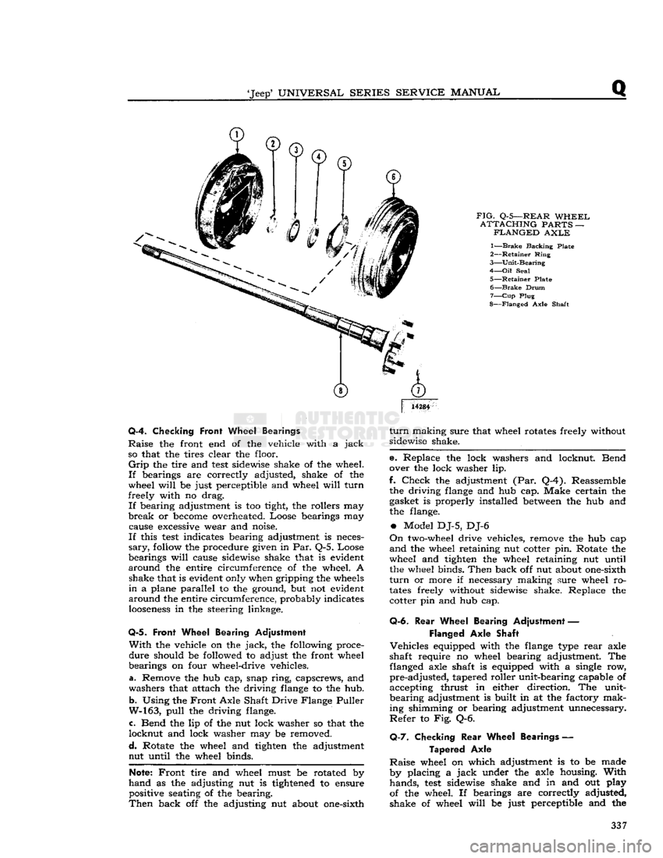
FIG.
Q-5—REAR
WHEEL
ATTACHING
PARTS —
FLANGED
AXLE
1—
Brake
Backing Plate
2—
Retainer
Ring
3—
Unit-Bearing
4—
Oil
Seal
5—
Retainer
Plate 6—
Brake
Drum
7—
Cup
Plug
8—
Flanged
Axle Shaft
14284
Q-4. Checking
Front
Wheel Bearings
Raise
the front end of the vehicle with a
jack
so that the tires clear the floor.
Grip
the tire and
test
sidewise shake of the wheel.
If
bearings are correctly adjusted, shake of the
wheel
will
be just perceptible and wheel
will
turn
freely with no drag.
If
bearing adjustment is too tight, the rollers may
break
or
become
overheated. Loose bearings may cause
excessive
wear and noise.
If
this
test
indicates bearing adjustment is neces
sary,
follow
the procedure given in Par. Q-5. Loose
bearings
will
cause sidewise shake that is evident
around
the entire circumference of the wheel. A shake that is evident only when gripping the
wheels
in
a plane parallel to the ground, but not evident
around
the entire circumference, probably indicates
looseness
in the steering linkage.
Q-5.
Front Wheel Bearing Adjustment
With
the vehicle on the
jack,
the following proce
dure
should be followed to adjust the front wheel
bearings on four wheel-drive vehicles.
a. Remove the hub cap, snap
ring,
capscrews, and
washers that attach the driving
flange
to the hub.
b.
Using the
Front
Axle Shaft Drive Flange Puller
W-163,
pull
the driving flange.
c. Bend the lip of the nut lock washer so that the
locknut
and lock washer may be removed.
d.
Rotate the wheel and tighten the adjustment nut until the wheel binds.
Note:
Front
tire and wheel must be rotated by
hand
as the adjusting nut is
tightened
to ensure positive seating of the bearing.
Then
back off the adjusting nut about one-sixth
turn
making sure that wheel rotates freely without
sidewise shake.
e. Replace the lock washers and locknut. Bend
over the lock washer lip.
f.
Check
the adjustment (Par. Q-4). Reassemble the driving
flange
and hub cap. Make certain the
gasket is properly installed
between
the hub and
the flange.
•
Model DJ-5, DJ-6
On
two-wheel drive vehicles, remove the hub cap
and
the wheel retaining nut cotter pin. Rotate the
wheel and tighten the wheel retaining nut until the wheel binds.
Then
back off nut about one-sixth
turn
or more if necessary making sure wheel ro
tates
freely without sidewise shake. Replace the cotter pin and hub cap.
Q-6.
Rear
Wheel Bearing Adjustment —
Flanged
Axle Shaft
Vehicles
equipped with the
flange
type
rear
axle
shaft require no wheel bearing adjustment. The flanged axle shaft is equipped with a single row,
pre-adjusted,
tapered roller unit-bearing capable of
accepting thrust in either direction. The unit-
bearing
adjustment is built in at the factory mak
ing shimming or bearing adjustment unnecessary.
Refer
to Fig. Q-6.
Q-7.
Checking
Rear
Wheel Bearings —
Tapered
Axle
Raise
wheel on which adjustment is to be made
by placing a
jack
under the axle housing.
With
hands,
test
sidewise shake and in and out play
of the wheel. If bearings are correctly adjusted,
shake of wheel
will
be just perceptible and the 337
Page 339 of 376
'Jeep'
UNIVERSAL
SERIES
SERVICE
MANUAL
Q
ice, provide maximum safety over all
types
of
terrain,
and furnish the medium on which the
vehicle can be maneuvered with ease. Although
there are other
elements
of tire service, inflation maintenance is the most important and in many
instances the most neglected. The tire pressure should be maintained for safe operation. An under- inflated tire is dangerous as too much flexing can
cause breakage of the casing. Overinflation in time
may
cause a blowout.
Upon
careful inspection of tires, it may be found
that improper wheel alignment, balance, grabbing
brakes,
poor driving habits, fast cornering or other
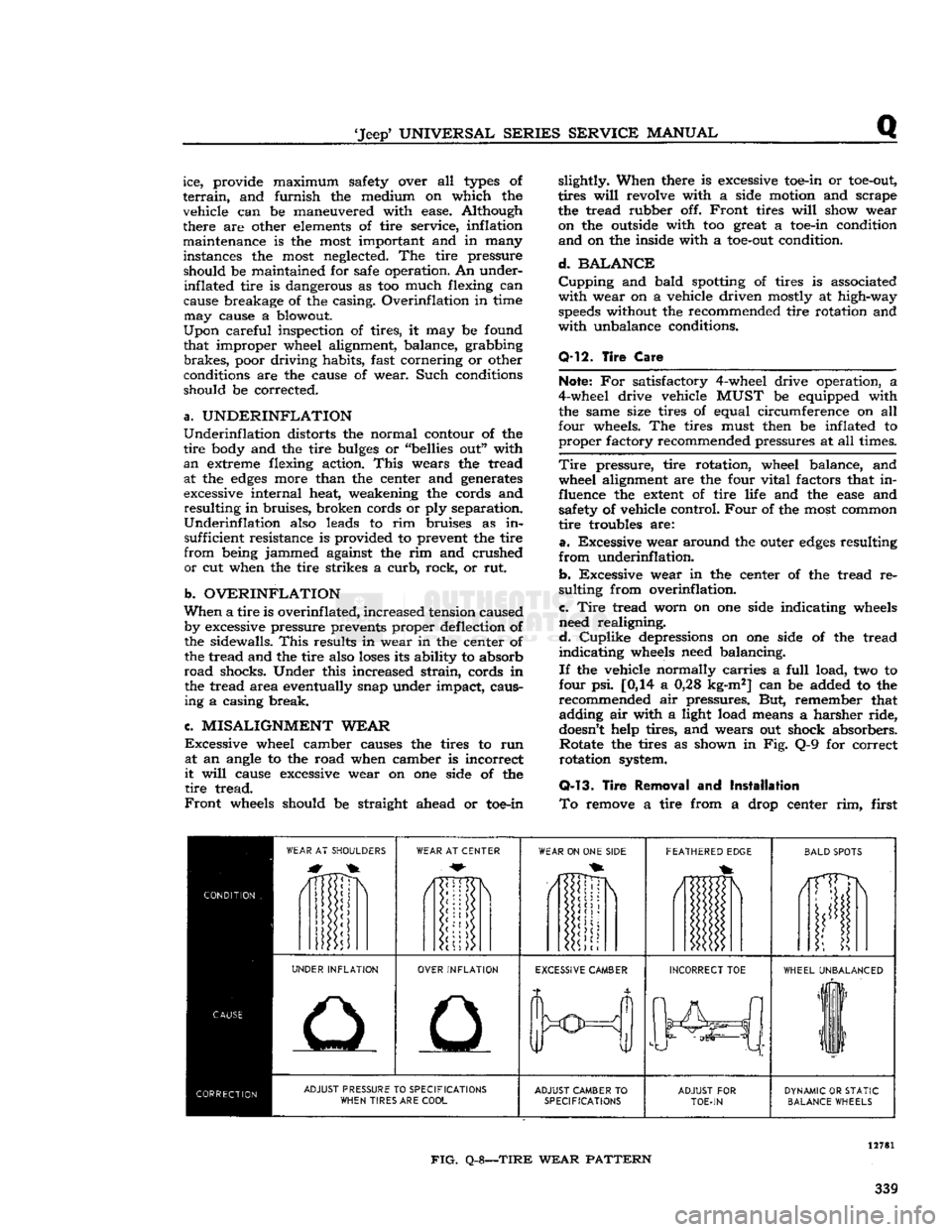
conditions are the cause of wear. Such conditions
should be corrected.
a.
UNDERINFLATION
Underinflation
distorts the normal contour of the
tire
body and the tire
bulges
or "bellies out" with
an
extreme flexing action.
This
wears the tread at the
edges
more than the center and generates
excessive internal heat, weakening the cords and
resulting
in bruises, broken cords or ply separation.
Underinflation
also leads to rim bruises as in sufficient resistance is provided to prevent the tire
from
being jammed against the rim and crushed
or
cut when the tire strikes a
curb,
rock, or rut.
b.
OVERINFLATION
When
a tire is
overinf
lated,
increased tension caused by excessive pressure prevents proper deflection of
the sidewalls.
This
results in wear in the center of the tread and the tire also
loses
its ability to absorb
road
shocks. Under this increased
strain,
cords in the tread area eventually snap under impact, causing a casing break.
c.
MISALIGNMENT
WEAR
Excessive
wheel camber causes the tires to run at an angle to the road when camber is incorrect
it
will
cause excessive wear on one side of the
tire
tread.
Front
wheels should be straight ahead or toe-in slightly. When there is excessive toe-in or
toe-out,
tires
will
revolve with a side motion and scrape
the tread rubber off.
Front
tires
will
show wear on the outside with too great a toe-in condition
and
on the inside with a
toe-out
condition.
d.
BALANCE
Cupping
and bald spotting of tires is associated
with
wear on a vehicle driven mostly at high-way
speeds
without the recommended tire rotation and
with
unbalance conditions.
Q-12.
Tire
Care
Note;
For satisfactory 4-wheel drive operation, a
4-wheel drive vehicle
MUST
be equipped with the same size tires of equal circumference on all
four wheels. The tires must then be inflated to
proper
factory recommended pressures at all times.
Tire
pressure, tire rotation, wheel balance, and wheel alignment are the four vital factors that in
fluence the
extent
of tire life and the
ease
and safety of vehicle control.
Four
of the most common
tire
troubles are:
a.
Excessive wear around the outer
edges
resulting
from
underinflation.
b.
Excessive wear in the center of the tread re
sulting from overinflation.
c.
Tire
tread worn on one side indicating wheels
need realigning.
d.
Cuplike
depressions on one side of the tread
indicating
wheels need balancing.
If
the vehicle normally carries a
full
load, two to
four psi. [0,14 a 0,28 kg-m2] can be added to the
recommended air pressures. But, remember that adding air with a light load means a harsher ride,
doesn't
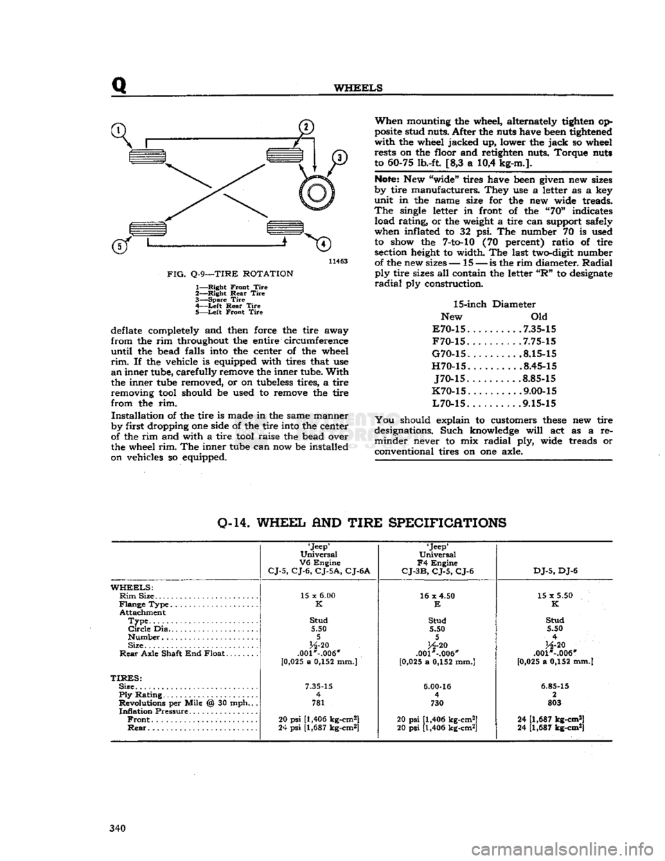
help tires, and wears out shock absorbers. Rotate the tires as shown in Fig. Q-9 for correct
rotation system.
Q-13.
Tire
Removal
and
Installation
To
remove a tire from a drop center rim, first
WEAR
AT SHOULDERS
WEAR
AT CENTER
WEAR
ON ONE
SIDE
FEATHERED
EDGE
BALD
SPOTS
/1TTDN
i
UNDER
INFLATION
OVER
INFLATION
EXCESSIVE
CAMBER
INCORRECT
TOE
WHEEL
UNBALANCED
liF
11
ADJUST
PRESSURE TO
SPECIFICATIONS
WHEN
TIRES ARE
COOL
ADJUST
CAMBER
TO
SPECIFICATIONS
ADJUST
FOR
TOE-IN
DYNAMIC
OR
STATIC
BALANCE
WHEELS
FIG.
Q-8—TIRE
WEAR
PATTERN
339
Page 340 of 376
Q
WHEELS
11463
FIG.
Q-9—TIRE
ROTATION
1—
Right
Front
Tire
2—
Right
Rear
Tire
3—
Spare
Tire
4—
-Left
Rear
Tire
5—
Left
Front
Tire
deflate completely and then force the tire away
from
the rim throughout the entire circumference
until
the bead falls into the center of the wheel
rim.
If the vehicle is equipped with tires that use
an
inner tube, carefully remove the inner tube.
With
the inner tube removed, or on tubeless tires, a tire
removing tool should be used to remove the tire
from
the rim.
Installation
of the tire is made in the same manner
by first dropping one side of the tire into the center
of the rim and with a tire tool raise the bead over
the wheel
rim.
The inner tube can now be installed
on vehicles so equipped.
When
mounting the wheel, alternately tighten op
posite stud nuts. After the nuts have been tightened
with
the wheel jacked up, lower the
jack
so wheel rests on the floor and retighten nuts. Torque nuts
to 60-75 lb.-ft. [8,3 a 10,4 kg-m.].
Note:
New "wide" tires have been given new sizes
by tire manufacturers. They use a letter as a key
unit
in the name size for the new wide treads.
The
single letter in front of the "70" indicates load rating, or the weight a tire can support safely
when inflated to 32 psi. The number 70 is used to show the
7-to-10
(70 percent) ratio of tire section height to width. The last two-digit number of the new sizes— 15 —
is
the rim diameter.
Radial
ply
tire sizes all contain the letter
"R"
to designate
radial
ply construction.
15-inch
Diameter
New Old
E70-15
7.35-15
F70-15
.7.75-15
G70-15
8.15-15
H70-15
8.45-15
J70-15
.8.85-15
K70-15
. .... .9.00-15
L70-15
9.15-15
You
should explain to customers
these
new tire
designations. Such knowledge
will
act as a re
minder
never to mix
radial
ply, wide treads or
conventional tires on one axle.
0-14.
WHEEL
AND
TIRE
SPECIFICATIONS
'Jeep'
Universal
V6
Engine
CJ-5,
CJ-6,
CJ-5A,
CJ-6A
'Jeep*
Universal
F4
Engine
CJ-3B,
CJ-5,
CJ-6
DJ-5,
DJ-6
WHEELS:
Rim
Size 15 x
6.00
16 x 4.50
15 x 5.50
K
E
K
Attachment
Type
Stud
Stud Stud
Circle
Dia 5.50 5.50 5.50
5 5
4
Size
H-20
H-20
H-20
Rear
Axle Shaft End Float .001*-.006"
.001"-.006" .001 *-.006"
[0 ,025 a 0,152 mm.)
[0,025 a 0,152 mm.] [0,025 a 0,152 mm.]
TIRES:
Size.
7.35-15
6.00-16
6.85-15
Ply
Rating 4
4 2
Revolutions per Mile @ 30 mph.. . 781 730 803
Inflation
Pressure
Front
20
psi
[1,406 kg-cm2]
20 psi [1,406 kg-cm2] 24 [1,687 kg-cm*]
Rear
24
psi
[1,687 kg-cm*]
20 psi [1,406 kg-cm2] 24 [1,687 kg-cm*] 340
Page 352 of 376
BODY
10728
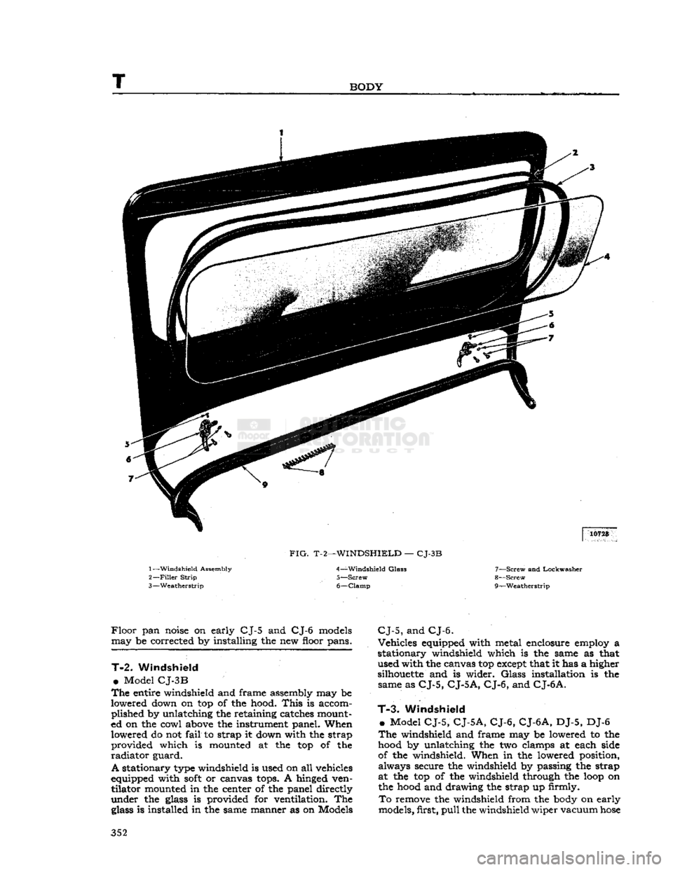
FIG.
T-2—WINDSHIELD
—
CJ-3B
1—
Windshield
Assembly
2—
Filler
Strip
3—
Weatherstrip 4—
Windshield
Glas3
5—
Screw
6—
Clamp
7—
Screw
and Lockwasher
8—
Screw
r
9— —Weatherstrip
Floor
pan
noise
on early CJ-5 and CJ-6
models
may be corrected by installing the new floor pans.
T-2.
Windshield
•
Model
CJ-3B
The
entire windshield and frame assembly may be
lowered down on top of the hood.
This
is accom plished by unlatching the retaining catches mount
ed on the cowl
above
the instrument panel. When lowered do not
fail
to strap it down with the strap provided which is mounted at the top of the
radiator
guard.
A
stationary
type
windshield is used on all vehicles
equipped with
soft
or canvas
tops.
A hinged ven tilator mounted in the center of the panel directly
under the
glass
is provided for ventilation. The
glass
is installed in the same manner as on Models
CJ-5,
and
CJ-6.
Vehicles equipped with metal enclosure employ a
stationary windshield which is the same as that used with the canvas top
except
that it has a higher
silhouette
and is wider.
Glass
installation is the same as
CJ-5,
CJ-5
A, CJ-6,
and
CJ-6
A.
T-3.
Windshield
»
Model
CJ-5, CJ-5A, CJ-6, CJ-6A,
DJ-5, DJ-6
The
windshield and frame may be lowered to the
hood
by unlatching the two clamps at each side
of the windshield. When in the lowered position, always secure the windshield by passing the strap
at the top of the windshield through the
loop
on the
hood
and drawing the strap up firmly.
To
remove the windshield from the
body
on early
models, first,
pull
the windshield wiper vacuum
hose
352