ECO mode JEEP CJ 1953 Owner's Manual
[x] Cancel search | Manufacturer: JEEP, Model Year: 1953, Model line: CJ, Model: JEEP CJ 1953Pages: 376, PDF Size: 19.96 MB
Page 208 of 376
H
ELECTRICAL
SYSTEM
sibility
of the cable shorting at the
engine
or frame.
Remove nut and lock washer securing the ignition
wire
to the solenoid
post
and remove the two screws and lock washers securing the solenoid to
the starter frame. Remove the switch,
b.
To install the solenoid switch reverse the re
moval
procedure given above.
H-10S.
STARTING MOTOR
—
DELCO
DAUNTLESS
V-6
ENGINE
Refer
to Fig. H-45.
The
starting motor used on the Dauntless V-6 en
gine
has an integral solenoid switch and enclosed
shift lever which first shifts the overrunning clutch
pinion into
engagement
with the ring gear on the
flywheel of the
engine
and then
closes
the electrical
circuit
to cause
engine
cranking. When the
engine
starts,
the overrunning clutch
disengages
to pre vent transfer of
engine
speed to the starting motor.
Note:
Should a service replacement starter motor
be required the factory recommends replacement
with
original equipment parts; however, should the need arise an existing starter motor (Delco or
Prestolite) could be replaced with the current
Delco-Remy
starter, model 1108375, with the
following modifications to the wiring harness. If
the existing starter motor wiring harness
does
not
provide a 12 ga. purple conduit wire, (connects the ignition switch to the starter motor) then a 12 ga.
purple
conduit wire 70 inches long, must be in
stalled.
Should the existing starter motor wiring
harness
contain a 16 ga. light blue conduit wire, (connects the ignition switch and starter motor)
bend this wire back and tape out of the way.
H-109.
Starting Motor Disassembly
a.
Before removing the starting motor from the
engine, disconnect leads and cover battery lead
terminal
with piece of
hose
or tape to prevent
short circuiting.
Note
locations of wiring connec
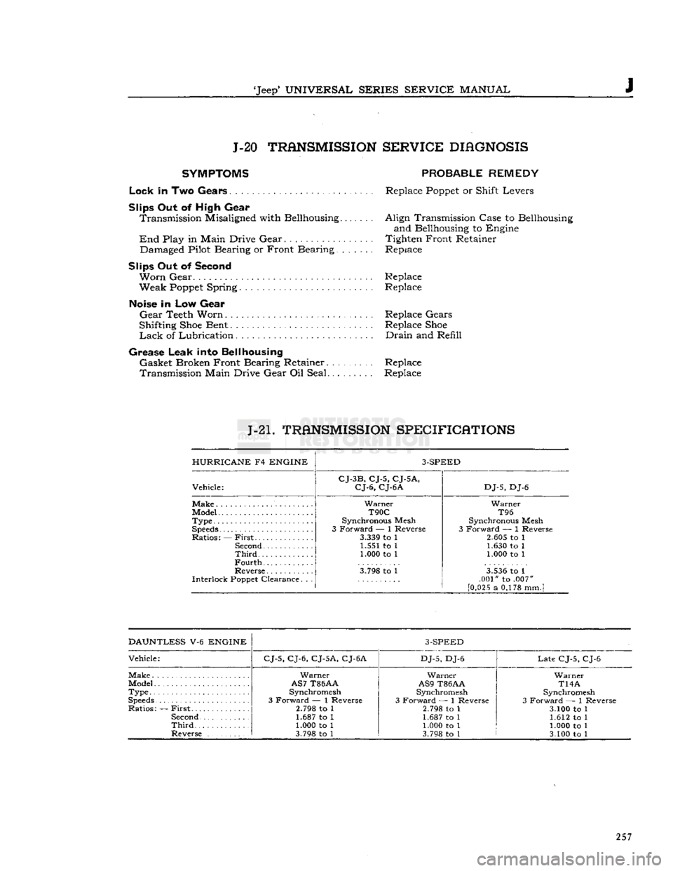
tions to assure proper reconnection. Remove the cap screw that secures the starting motor to the
angle bracket on the side of the engine. Remove
the two cap screws that secure the drive end of
the starting motor to the cylinder block; remove
the starting motor.
b.
Remove terminal nut and disconnect field lead,
which
passes through grommet at top of motor,
from
motor terminal of solenoid. Remove two
thru
bolts
from motor. Remove commutator end frame
and
field frame assembly from solenoid and drive assembly.
e.
Pull
out pivot pins of brush holders and remove each of two brush holder and spring assemblies
from
field housing. Remove screws which attach
brushes and leads to holders.
d.
Remove armature and drive assembly from
drive
housing. Remove thrust collar from pinion
end of armature shaft. Remove leather thrust
washer
from
opposite
end of shaft.
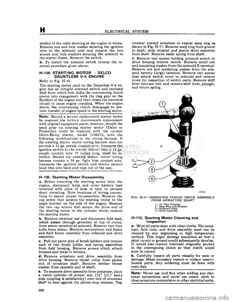
e. To separate drive assembly from
armature,
place
a
metal cylinder of proper size (J^" [12,7 mm.]
pipe coupling is satisfactory) over end of armature
shaft to bear against the pinion
stop
retainer. Tap
retainer
toward armature to
expose
snap ring as
shown in
Fig.
H-47. Remove snap ring from
groove
in
shaft; slide retainer and pinion drive assembly
from
shaft. Remove assist spring from shaft,
f.
Remove two screws holding solenoid switch to
drive
housing remove switch. Remove small nut
and
insulating washer from the solenoid S terminal.
Remove nut and insulating washer from the
sole
noid battery (large) terminal. Remove two screws that attach switch cover to solenoid and remove cover for inspection of switch parts. Remove shift
lever fulcrum bolt and remove shift lever, plunger,
and
return spring.
12765
FIG.
H-47—REMOVING PINION
DRIVE
ASSEMBLY
FROM
ARMATURE SHAFT
1— XA ' Pipe Coupling
2—
Snap
Ring
and Retainer
3—
Armature
Shaft
4—
Drive
Assembly
H-110.
Starting
Motor
Cleaning and
Inspection
a.
Wipe all parts clean with clean cloths. The
arma
ture,
field coils, and drive assembly must not be
cleaned by any degreasing or high temperature
method.
This
might damage insulation so that a
short
circuit
or ground would subsequently develop.
It
would also remove lubricant originally packed
in
the overrunning clutch so that clutch would
soon
be ruined.
b.
Carefully
inspect all parts visually for wear or
damage. Make necessary repairs or replace unserv
iceable parts. Any soldering must be
done
with
rosin
flux.
Note:
Never use acid flux when solding any elec
trical
connections and never use emery cloth to
clean
armature
commutator or other
electrical
units. 208
Page 212 of 376
H
ELECTRICAL
SYSTEM
H-124. Testing Indicators and Gauges
Two
gauges
(fuel and temperature) and two in dicators (oil pressure and battery charge) that are
located in the instrument cluster are electrically operated.
The
fuel
gauge
is connected by a single wire to a
float-and-slide-rheostat sending unit in the fuel
tank.
The
temperature
gauge
is connected by a single
wire
to a resistance-type sending unit mounted on the engine.
The
battery charge indicator operates when there
is a difference in potential
between
the generator
and
the battery
.The
battery charge indicator lights
when the generator is not charging the battery. The
indicator
light
goes
out when the generator
begins
to charge the battery.
The
oil pressure indicator is connected by a single
wire
to a diaphragm switch located on the engine.
When
engine
oil pressure is low or zero and the
ignition switch is on, the oil pressure indicator
will
light. When
engine
speed is increased slightly above idle speed, raising the oil pressure to approximately 6 psi. [0,2 kg-cm2], the diaphragm switch
will
open the circuit and the indicator light
will
go out.
A
voltage
regulator maintains a constant
voltage
to the
gauges
in normal operation. On early vehicles,
this
voltage
regulator was mounted on the
rear
of
the instrument cluster. On current vehicles, the
voltage
regulator is integral with the fuel
gauge.
Should
trouble
develop
in the
gauges,
first check the regulator (fuel
gauge
on current production vehicle). If the
voltage
to the regulator is below 10 volts system low
gauge
readings
will
result.
Voltage in
excess
of 16 volts
will
not affect
gauge
readings but may result in premature wear of the
regulator contacts. If the
voltage
to the regulator is
within
the above limits, check the electrical con nections to the regulator (or fuel gauge), especially
the ground connection. If the readings of all the
gauges
is too high, or they all read too low, replace
the regulator (or fuel gauge).
If
the temperature
gauge
or heat indicator in the
instrument cluster have failed, the cause may
originate from the jumper bar shorting out against the instrument case.
Check
the jumper bar
between
the temperature
gauge
and heat indicator at the
rear
of the instrument case. On later production vehicles, the jumper bar is covered with an in
sulating
sleeve
to protect it from shorting out
against the instrument case. If the jumper bar
does
not have this
sleeve,
either install one or
wrap
the bar with plastic electrical tape to
half
an
inch [12,7 mm.] from each end. When installing the jumper bar, be sure the curved
segment
is
closest to the fuel
gauge.
Should
only one of the two
gauges
register incor
rectly,
check the lead wire from the
gauge
to the
sending unit for shorts or open connections. Next disconnect the
gauge
from the sending unit, and
connect the
gauge
to a new fuel tank sending unit
which
has been grounded to the vehicle.
If
the
gauge
registers incorrectly when operating the new unit,
replace the
gauge;
if correctly, replace the sending
unit.
Should
a new fuel tank unit not be available for testing, use a 12-volt
test
light in its place. When
the
gauge
is operating correctly, the pointer
will
move
approximately three-quarters across the
dial.
On
some
vehicles, the temperature
gauge
may
register on or
close
to the H (hot)
mark
when
coolant temperature is
190°F.
to
200°F.
[88°C.
a
93°C.].
In such cases, a 25-ohm,
1-watt
resistor
may be installed on the temperature
gauge
which
will
place the pointer just beyond the center
mark
at a coolant temperature of
190°F.
to
200°F.
Install
the resistor
between
the two terminals on the back
of the
gauge.
Insulate the
exposed
leads of the resistor with electrical tape.
If
the oil pressure indicator
does
not indicate cor
rectly,
first check the light bulb. Next check all
connections and lead wires. If, after all possible
defects
are corrected, the indicator light
does
not go on and off properly, then the diaphragm type
switch in the cylinder block should be replaced.
H-12S.
LIGHTING SYSTEM The
wiring of the lighting systems is shown in
the wiring diagrams, which indicate the various units in relation to their positions in the vehicle.
The
wires in the various circuits are of different
colors or are marked by tracers to aid when check
ing individual circuits.
The
lighting circuits of all models are protected by
an
overload circuit breaker mounted on the back of the main light switch and no replaceable fuse is
required.
The
upper and lower headlight beams are con
trolled by a
foot
switch located on the toe board
to the left of the clutch pedal.
H-126.
Main
Light
Switch
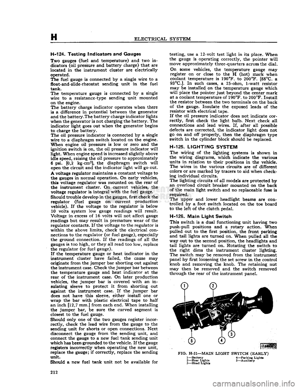
This
switch is a dual functioning unit having two
push-pull
positions and a rotary action. When
pulled out to the first position, the front parking
and
tail
lights are turned on. When pulled all the
way out to the second position, the headlights and
tail
lights are turned on. Rotating the switch to
the right dims the instrument cluster lighting.
The
switch may be removed from the instrument
panel by first loosening the set screw in the control
knob and removing the knob. The retaining nut may then be removed and the switch removed
through the
rear
of the instrument panel.
FIG.
H-51—MAIN
LIGHT
SWITCH
(EARLY)
1—
Battery
4—Parking Lights
2—
Rear
Lights 5—Auxiliary
3—
Head
Lights
212
Page 223 of 376
'Jeep'
UNIVERSAL SERIES SERVICE
MANUAL
H
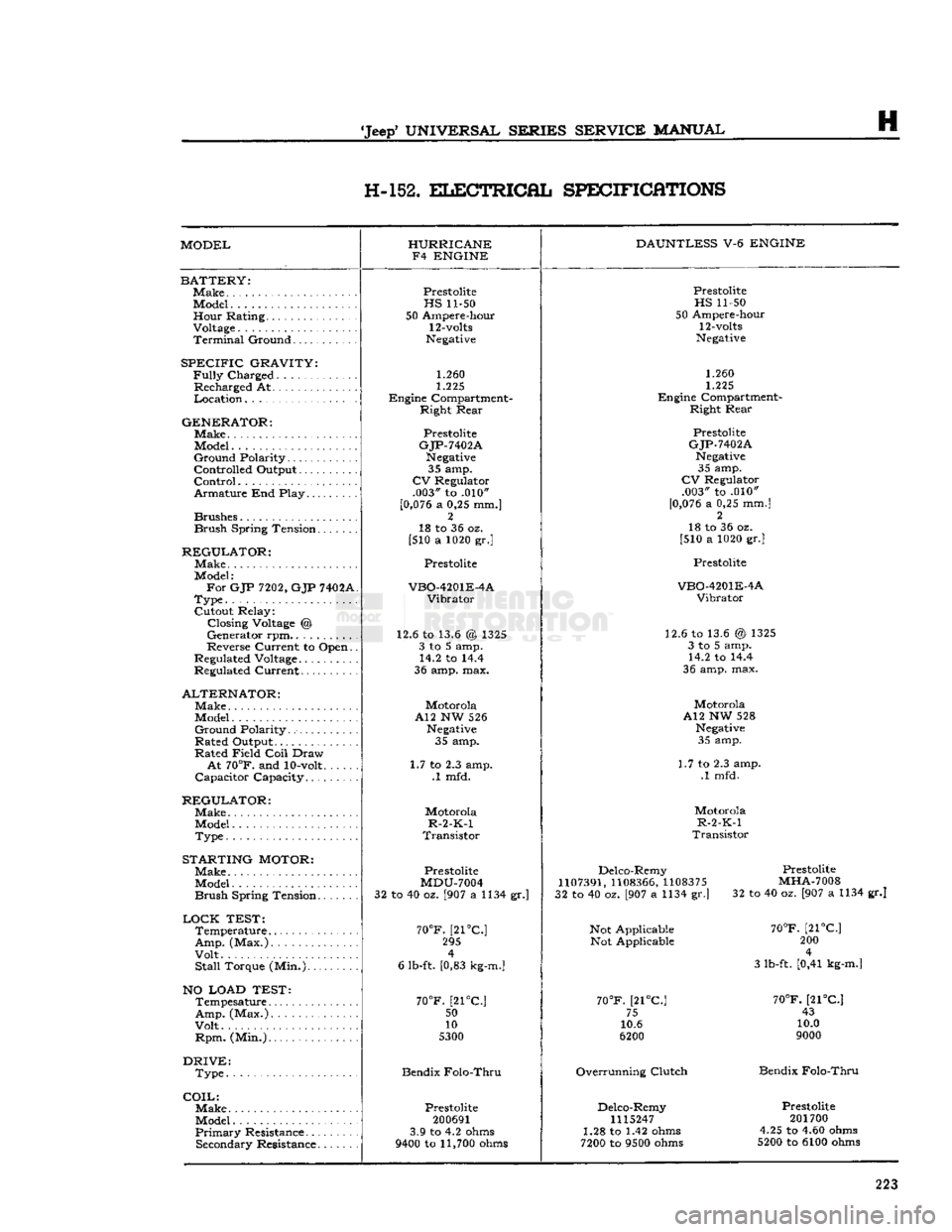
H-152.
ELECTRICAL
SPECIFICATIONS
MODEL HURRICANE
F4 ENGINE DAUNTLESS
V-6
ENGINE
BATTERY:
Make
Model Hour Rating.
Voltage
Terminal
Ground
SPECIFIC
GRAVITY:
Fully
Charged
Recharged At
Location
GENERATOR:
Make.
Model
Ground
Polarity
Controlled Output
Control
Armature End Play
Brushes
Brush
Spring Tension
REGULATOR:
Make
Model:
For
GJP
7202,
GJP
7402A
Type
Cutout Relay: Closing
Voltage
@
Generator rpm..........
Reverse Current to Open.
Regulated
Voltage
Regulated Current
ALTERNATOR:
Make
Model
Ground
Polarity
Rated Output
Rated Field
Coil
Draw
At
70°F.
and
10-volt
Capacitor Capacity
REGULATOR:
Make
Model
Type
STARTING
MOTOR:
Make
Model
Brush
Spring Tension
LOCK
TEST:
Temperature
Amp.
(Max.)
Volt
Stall
Torque (Min.)
NO LOAD TEST:
Tempesature
Amp.
(Max.)
Volt
Rpm.
(Min.)
DRIVE:
Type
COIL:
Make.
Model
Primary
Resistance Secondary Resistance
Prestolite
HS
11-50
50 Ampere-hour
12-volts
Negative
1.260
1.225
Engine Compartment- Right Rear
Prestolite
GJP-7402A
Negative
35 amp.
CV
Regulator .003" to .010"
[0,076
a 0,25 mm.] 2
18 to 36 oz.
[510 a 1020 gr.]
Prestolite
VBO-4201E-4A
Vibrator
12.6 to 13.6 @ 1325 3 to 5 amp. 14.2 to 14.4
36 amp. max.
Motorola
A12 NW 526
Negative
35 amp.
1.7 to 2.3 amp. .1 mfd.
Motorola
R-2-K-1
Transistor
Prestolite
MDU-7004
32 to 40 oz. [907 a 1134 gr.]
70°F.
[21°C] 295 4
6 lb-ft. [0,83
kg-m.]
70°F.
[21°C.;
50
10
5300
Bendix Folo-Thru
Prestolite
200691
3.9 to 4.2
ohms
9400
to
11,700
ohms
Prestolite
HS
11-50
50 Ampere-hour
12-volts
Negative
1.260
1.225
Engine Compartment- Right Rear
Prestolite
GJP-7402A
Negative
35 amp.
CV
Regulator .003" to .010"
[0,076
a 0,25 mm.] 2
18 to 36 oz.
[510 a 1020 gr.]
Prestolite
VBO-4201E-4A
Vibrator
12.6 to 13.6 @ 1325 3 to 5 amp. 14.2 to 14.4
36 amp. max.
Motorola
A12 NW 528
Negative
35 amp.
1.7 to 2.3 amp. .1 mfd.
Motorola
R-2-K-1
Transistor
Delco-Remy
1107391,
1108366,
1108375
32 to 40 oz. [907 a 1134 gr.]
Not Applicable Not Applicable
70°F.
[21°C] 75
10.6
6200
Overrunning Clutch Delco-Remy
1115247
1.28 to 1.42
ohms
7200
to
9500
ohms
Prestolite
MHA-7008
32 to 40 oz. [907 a 1134 gr.]
70°F.
[21°C] 200 4
3 lb-ft. [0,41
kg-m.]
70°F.
[21°C] 43
10.0
9000
Bendix Folo-Thru
Prestolite
201700
4.25 to 4.60
ohms
5200
to 6100
ohms
223
Page 226 of 376
![JEEP CJ 1953 Owners Manual
I
CLUTCH 1-1.
GENERAL
The
clutch on current Jeep vehicles is either
Auburn
or Borg and Beck manufactured. Vehicles
equipped with F4-134
engines
have an
Auburn
9.25" [23,4 cm.] single JEEP CJ 1953 Owners Manual
I
CLUTCH 1-1.
GENERAL
The
clutch on current Jeep vehicles is either
Auburn
or Borg and Beck manufactured. Vehicles
equipped with F4-134
engines
have an
Auburn
9.25" [23,4 cm.] single](/img/16/57040/w960_57040-225.png)
I
CLUTCH 1-1.
GENERAL
The
clutch on current 'Jeep' vehicles is either
Auburn
or Borg and Beck manufactured. Vehicles
equipped with F4-134
engines
have an
Auburn
9.25" [23,4 cm.] single plate dry-disc clutch. The
pressure plate has three coil pressure springs and
three levers or fingers.
The
V6-225
engine
is equipped with a 10.4" [26,4
cm.] Borg and Beck single plate dry-disc clutch.
The
pressure plate utilizes either a finger-type
diaphragm spring, or a coil
type
spring pressure plate for clutch release.
The
driven plates of all
models
are built with
vibra
tion damper springs and have two flexible facings
which
provide
smooth
engagement
of the
engine
power.
Early
'Jeep' vehicles equipped with a Dauntless
V-6
engine
use a 10.4" [26,4 cm.] single plate, dry-
disc clutch, incorporating a diaphram-type spring assembly.
The
clutch is of the centrifugal single dry disc
type
and
consists of the clutch disc, pressure plate and
the clutch release bearing.
The
clutch is actuated by a clutch pedal and a
series of mechanical linkage.
When
the clutch pedal is in the
engaged
position,
the clutch disc facings are clamped
between
the
friction surface of the
engine
flywheel and the face of the clutch pressure plate, thereby connect
ing
engine
power to the transmission. Depressing
the clutch pedal actuates the clutch release shaft
fork
which
moves
the clutch release bearing against
the clutch fingers.
This,
in
turn,
moves
the pressure
plate away from the clutch disc. Since the disc is splined to the transmission input shaft, the clutch
disc and transmission input shaft
will
stop
when
the clutch is disengaged, thereby disconnecting
engine
power from the transmission.
1-2.
Clutch
Maintenance
To
obtain normal life and satisfactory performance
from any clutch it must be correctly operated and
properly maintained. Two conditions which shorten
clutch life are continuous operation of the clutch
release bearing and clutch slippage.
The
clutch release bearing is
designed
for inter
mittent use. If run continuously the bearing
lubri
cant
will
become
exhausted causing the bearing to
become
dry, noisy, or
will
seize, resulting in clutch
finger or diaphragm wear. The clutch must be properly adjusted so that the release bearing is
free of the clutch fingers or diaphragm at all times,
except
when the clutch pedal is depressed.
Excessive
clutch slippage
often
occurs when the
vehicle is overloaded, the vehicle load is applied
too quickly, or when the pressure of the clutch fingers or diaphragm is only partially applied to the clutch plate.
Friction
between
the clutch facing
and
flywheel produces
excessive
heat causing
burned,
glazed and worn linings, resulting in shortened clutch life. Avoid clutch slippage under
heavy loads by using a lower gear or reducing the load.
1-3.
Clutch
Pedal
Linkage
and Adjustment
Adjust
the clutch pedal free travel whenever the clutch
does
not
disengage
properly, or when new
clutch parts are installed. Improper adjustment of
the clutch pedal free travel is one of the
most
fre
quent causes of clutch failure and can be a con tributing factor in
some
transmission failures.
As
the clutch facings wear the free travel of the clutch pedal diminishes. When sufficient wear oc
curs
the pedal clearance must be adjusted.
Two
types
of clutch linkage have
been
used on Jeep vehicles, a cross shaft
tube
and lever
type
shown in Fig. 1-1, and a clutch control cable
type
shown in Fig. 1-2. The clutch pedal adjustment
procedures for both
type
linkages are as follows.
•
Cross
Shaft
Lever
and Tube Type
Refer
to Fig. 1-1.
Note:
Two different
Clutch
Control
Lever
and
Tube
Assemblies have
been
installed on 'Jeep*
Universal
vehicles equipped with a V-6
engine
and
T14A
transmission.
Should difficulty in shifting the transmission be
noted, check the length of the clutch release pedal
rod,
item (16) in Fig. 1-1. Measure the distance
between
the centerlines of the cotter key holes.
FIG.
1-2—CLUTCH
LINKAGE AND
ADJUSTMENT,
CONTROL
CABLE TYPE
A—Top
View,
Cable
to
Clutch
Fork
1—
Retracting
Spring
(Clutch
Fork)
2—
Clutch
Fork
3—
Ball
Adjusting Nut
4—
Lock
Nut 5—
Clutch
Cable
B—Side
View,
Cable
to
Clutch
Pedal 6—
Clutch
Cable
Support
Bracket
7—
Clutch
Cable
Housing
8—
Anchor
Bracket-to-Frame Side
Rail
9—
Retracting
Spring
(Clutch
Pedal)
10—Clutch
Pedal Assembly
*
© © ©
1437S
226
Page 230 of 376
CLUTCH
is deeply scored or grooved, the part should be
replaced.
b. Inspect driven plate for wear or damage to fac
ings,
loose
rivets, broken or
loose
torsion springs,
and
flattened cushion springs. If facings are worn
near
rivets or are oily, replace the plate assembly.
A
slight amount of oil on clutch facings
will
cause
clutch
grab and chatter; excessive oil on facings
will
cause slippage. It is not practical to remove
oil
with solvents or by buffing since oil
will
con
tinue to bleed from facing material when hot. If
oil
is found on driven plate facings, examine trans
mission drainback hole, pilot bushing,
engine
rear
main
bearing and other points of possible oil leakage. Test the fit of driven plate hub on trans
mission main drive gear for an easy sliding fit.
c. Inspect clutch release bearing for scoring or ex cessive wear on front contact face. Test for rough
ness
of balls and races by pressing and turning
front race slowly. Inspect main drive gear pilot
bushing in crankshaft. Replace bushing if it is rough or worn. Regardless of whether the old plate
or
a new plate is to be installed, check the plate
for runout. Slide the driven plate, front side first,
over the transmission main drive gear shaft so that
it
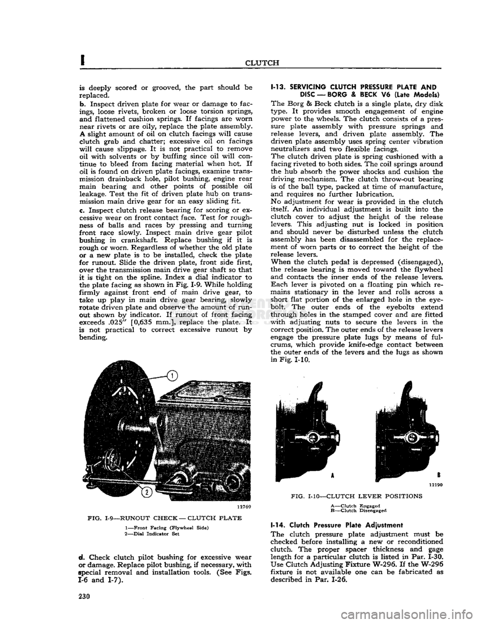
is tight on the spline. Index a
dial
indicator to the plate facing as shown in
Fig.
1-9. While holding
firmly
against front end of main drive gear, to take up play in main drive gear bearing, slowly
rotate driven plate and observe the amount of
run
out shown by indicator. If runout of front facing
exceeds
.025" [0,635 mm.], replace the plate. It
is not practical to correct excessive runout by bending. 12769
FIG.
1-9—RUNOUT
CHECK
—
CLUTCH
PLATE
1—
Front
Facing
(Flywheel
Side)
2—
Dial
Indicator
Set
d.
Check
clutch pilot bushing for excessive wear
or
damage. Replace pilot bushing, if necessary, with
special
removal and installation
tools.
(See
Figs.
1-6 and 1-7). 1-13.
SERVICING
CLUTCH
PRESSURE
PLATE
AND
DISC
—
BORG
&
BECK
V6
(Late
Models)
The
Borg & Beck clutch is a single plate, dry disk
type. It provides smooth
engagement
of
engine
power to the wheels. The clutch consists of a pres
sure
plate assembly with pressure springs and
release levers, and driven plate assembly. The
driven
plate assembly
uses
spring center vibration
neutralizes and two flexible facings.
The
clutch driven plate is spring cushioned with a facing riveted to both sides. The coil springs around
the hub absorb the power shocks and cushion the
driving
mechanism. The clutch throw-out bearing is of the
ball
type, packed at time of manufacture,
and
requires no further lubrication.
No adjustment for wear is provided in the clutch itself. An individual adjustment is built into the
clutch
cover to adjust the height of the release
levers.
This
adjusting nut is locked in position
and
should never be disturbed unless the clutch assembly has been disassembled for the replace
ment of worn parts or to correct the height of the release levers.
When
the clutch pedal is depressed (disengaged),
the release bearing is moved toward the flywheel
and
contacts the inner ends of the release levers.
Each
lever is pivoted on a floating pin which re
mains stationary in the lever and rolls across a short flat portion of the enlarged
hole
in the eye-
bolt. The outer ends of the
eyebolts
extend
through
holes
in the stamped cover and are fitted
with
adjusting nuts to secure the levers in the
correct
position. The outer ends of the release levers
engage
the pressure plate lugs by means of ful-
crums,
which provide knife-edge contact
between
the outer ends of the levers and the lugs as shown
in
Fig.
I-10. 12190
FIG.
MO—CLUTCH
LEVER
POSITIONS
A—Clutch
Engaged
B—Clutch
Disengaged 1-14.
Clutch
Pressure Plate Adjustment
The
clutch pressure plate adjustment must be
checked before installing a new or reconditioned
clutch.
The proper spacer thickness and
gage
length for a particular clutch is listed in Par. 1-30.
Use
Clutch
Adjusting
Fixture
W-296. If the W-296
fixture is not available one can be fabricated as
described in Par. 1-26. 230
Page 239 of 376
'Jeep'
UNIVERSAL
SERIES
SERVICE
MANUAL
J
THREE-SPEED
TRANSMISSION
Contents
SUBJECT
PAR.
GENERAL
J-l
TRANSMISSION
SHIFTING
CONTROL.
. J-2
TRANSMISSION
REMOTE
CONTROL
ADJUSTMENT
J-3
REMOTE
CONTROL
DISASSEMBLY
J-4
REMOTE
CONTROL
REASSEMBLY.
. . . . J-5
TRANSMISSION
REMOVAL
J-6
SEPARATING
TRANSMISSION
AND
TRANSFER
CASE
J-7
SUBJECT
PAR.
DISASSEMBLY
OF
CANE
SHIFT
TRANSMISSION
J-8, J-12, J-16
Transmission
Cleaning and
Inspection J-10, J-18
Transmission
Interlocking Sleeve Inspection J-9
REASSEMBLY
OF
CANE
SHIFT
TRANSMISSION
J-ll,
J-14, J-19
SERVICE
DIAGNOSIS
J-20
TRANSMISSION
SPECIFICATIONS
J-21
J-1.
GENERAL
A
three speed synchromesh transmission is standard
equipment on all 'Jeep' Universal vehicles.
The
models T90 and T96 transmissions are used
with
the
Hurricane
F4 engine, and models
T86AA
and
T14A transmissions are used with the Daunt
less
V-6 engine. All model transmissions are similar
in
design with exception of the T14A which is a
fully
synchronized (all forward gears) transmission
with
helical drive gears throughout.
The
transmission assembly is attached to the
rear
face of the flywheel bell housing and is supported on a rubber insulator at the frame center cross member which forms the
rear
engine
support.
All
4-wheel-drive vehicles are equipped with a
transfer
case attached to the
rear
of the transmission.
Transfer
case service and repair procedures
are
described in Section
K.
Models
CJ-5A,
and
CJ-6A
are equipped with the
same transmission, but with a remote control shift.
Models DJ-5 and DJ-6 are equipped with a similar
transmission,
however, the construction is
some
what different because it is not designed to receive a transfer case for four-wheel drive.
For
DJ-5 and DJ-6 2WD vehicles, the trans mission repair procedures begin with Par. J-12.
J-2.
TRANSMISSION SHIFTING CONTROL
The
shift of the three-speed transmission is smooth
and
positive. The cane control lever shifts the trans
mission gears direct from the shift control housing
mounted to the top side of the transmission housing.
The
remote control lever shifts the transmission
gears through remote control rods attached to the
adjusting
levers of the shift shafts protruding from the left side of the transmission housing. Poppet
balls and springs retain the transmission gears in mesh and an interlocking mechanism prevents
shifting into two gears at the same time.
J-3.
Transmission Remote Control Adjustment
•
Early
CJ-5A,
CJ-6A
First
disconnect the transmission shift rods from the remote control levers.
Check
for binding of
the remote control shaft on the steering column
and
make the necessary corrections to eliminate any binding condition.
If
the shift is not smooth and positive, first make
sure
the gears are in neutral position then remove
the shift rods at the transmission by removing
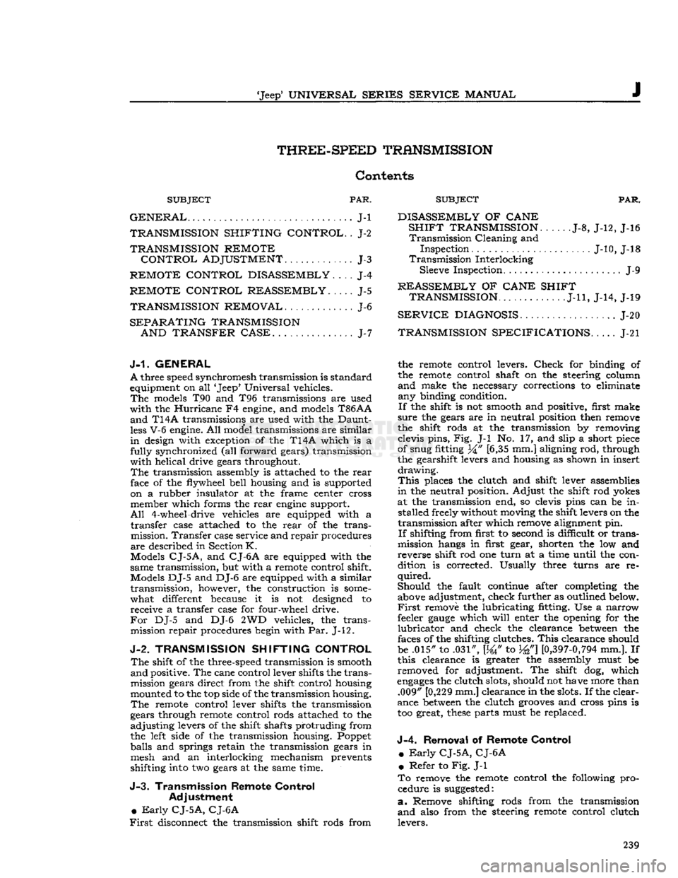
clevis pins, Fig. J-l No. 17, and slip a short piece
of snug fitting 34" [6,35 mm.] aligning rod, through
the gearshift levers and housing as shown in insert
drawing.
This
places the clutch and shift lever assemblies
in
the neutral position. Adjust the shift rod yokes
at the transmission end, so clevis pins can be in stalled freely without moving the shift levers on the
transmission after which remove alignment pin.
If
shifting from first to second is difficult or trans
mission hangs in first gear, shorten the low and
reverse shift rod one
turn
at a time until the con
dition is corrected. Usually three turns are re
quired.
Should
the fault continue after completing the above adjustment, check further as outlined below.
First
remove the lubricating fitting. Use a narrow
feeler
gauge
which
will
enter the opening for the
lubricator
and check the clearance
between
the
faces of the shifting clutches.
This
clearance should
be .015" to .031", [W to W]
[0,397-0,794
mm.]. If
this clearance is greater the assembly must be removed for adjustment. The shift dog, which
engages
the clutch slots, should not have more than .009" [0,229 mm.] clearance in the slots. If the clear
ance
between
the clutch
grooves
and cross pins is
too great,
these
parts must be replaced.
J-4.
Removal
of
Remote Control
m
Early
CJ-5A,
CJ-6A
•
Refer to Fig. J-l
To
remove the remote control the following pro cedure is
suggested:
a.
Remove shifting rods from the transmission
and
also from the steering remote control clutch levers. 239
Page 241 of 376
'Jeep'
UNIVERSAL
SERIES
SERVICE
MANUAL
J
10489
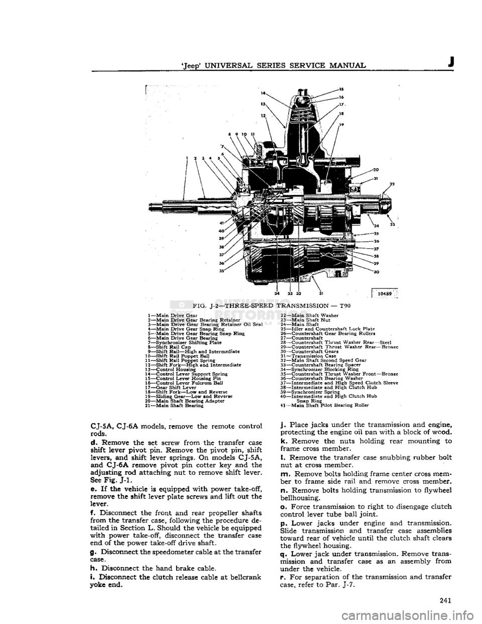
FIG.
J-2—THREE-SPEED
TRANSMISSION
— T90 1—
Main
Drive
Gear
2—
Main
Drive
Gear
Bearing
Retainer
3—
Main
Drive
Gear
Bearing
Retainer Oil
Seal
4—
Main
Drive
Gear
Snap
Ring
5—
Main
Drive
Gear
Bearing
Snap
Ring
6—
Main
Drive
Gear
Bearing
7—
Synchronizer
Shifting Plate
8—
Shift
Rail
Cap
9—
Shift
Rail—High
and Intermediate
10—
Shift
Rail
Poppet
Ball
11—
Shift
Rail
Poppet
Spring
12—
Shift
Fork—High
and Intermediate
13—
Control
Housing
14—
Control
Lever
Support
Spring
15—
Control
Lever
Housing Pin
16—
Control
Lever
Fulcrum
Ball
17—
Gear
Shift
Lever
18—
Shift
Fork—Low
and Reverse
19—
Sliding
Gear—Low
and Reverse
20—
Main
Shaft
Bearing
Adapter
21—
Main
Shaft
Bearing
22—
Main
Shaft
Washer
23—
Main
Shaft Nut
24—
Main
Shaft
25—
Idler
and Countershaft
Lock
Plate
26—
^Countershaft
Gear
Bearing
Rollers
2
7—Countershaft
28—
Countershaft
Thrust
Washer
Rear—Steel
29—
Countershaft
Thrust
Washer
Rear—Bronze
30—
Countershaft
Gears
31—
Transmission
Case
32—
Main
Shaft Second Speed
Gear
33—
Countershaft
Bearing
Spacer
34—
Synchronizer
Blocking
Ring
35—
Countershaft
Thrust
Washer
Front—Bronze
36—
Countershaft
Bearing
Washer
37—
Intermediate
and High Speed
Clutch
Sleeve
38—
Intermediate
and High
Clutch
Hub
39—
Synchronizer
Spring
40—
Intermediate
and High
Clutch
Hub
Snap
Ring
41—
Main
Shaft Pilot
Bearing
Roller
CJ-5A,
CJ-6A
models, remove the remote control
rods.
d.
Remove the set screw from the transfer case
shift lever pivot pin. Remove the pivot pin, shift
levers,
and shift lever springs. On models
CJ-5A,
and
CJ-6A
remove pivot pin cotter key and the
adjusting
rod attaching nut to remove shift lever.
See
Fig.
J-l.
e. If the vehicle is equipped with power take-off,
remove the shift lever plate screws and lift out the
lever.
f. Disconnect the front and
rear
propeller shafts
from
the transfer case, following the procedure de
tailed
in Section
L.
Should the vehicle be equipped
with
power take-off, disconnect the transfer case end of the power take-off drive shaft.
g. Disconnect the
speedometer
cable at the transfer case.
h.
Disconnect the hand brake cable.
i.
Disconnect the clutch release cable at beilcrank
yoke end.
j.
Place
jacks
under the transmission and engine,
protecting the
engine
oil pan with a block of wood,
k.
Remove the nuts holding
rear
mounting to
frame
cross member.
I.
Remove the transfer case snubbing rubber bolt
nut at cross member.
m.
Remove
bolts
holding frame center cross mem
ber
to frame side
rail
and remove cross member,
n.
Remove
bolts
holding transmission to flywheel
bellhousing.
o.
Force
transmission to right to
disengage
clutch
control
lever tube
ball
joint.
p.
Lower
jacks
under
engine
and transmission.
Slide
transmission and transfer case assemblies
toward
rear
of vehicle until the clutch shaft clears the flywheel housing.
q.
Lower
jack
under transmission. Remove trans mission and transfer case as an assembly from
under
the vehicle.
r.
For separation of the transmission and transfer
case, refer to Par. J-7. 241
Page 245 of 376
'Jeep*
UNIVERSAL
SERIES'
SERVICE
MANUAL
lightly
on the end of the
mainshaft
to
loosen
the
gear
and
separate
the two
units.
J-8.
Disassembly
—
T90,
T86AA
®
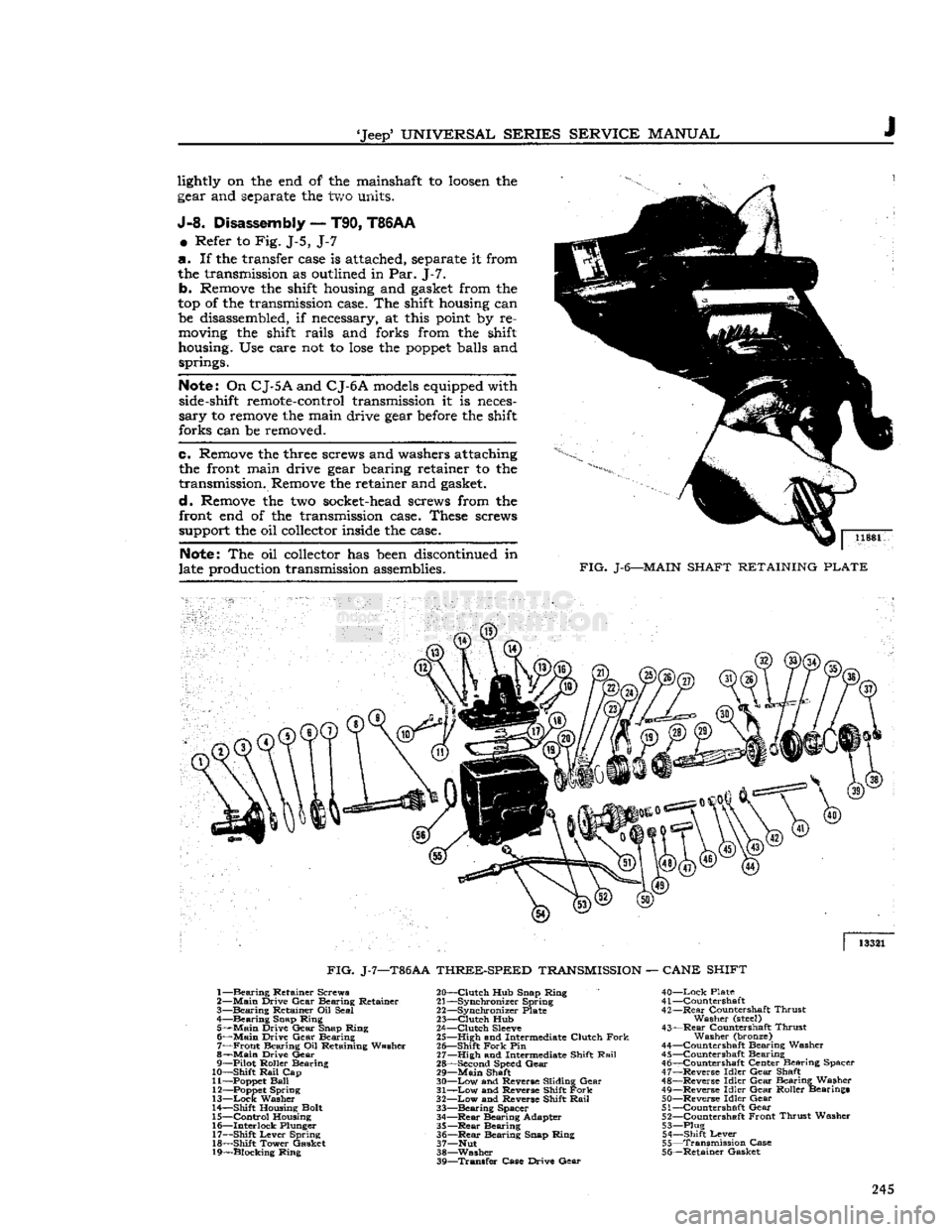
Refer to Fig. J-5, J-7
a. If the transfer
case
is
attached,
separate
it from
the
transmission
as
outlined
in Par. J-7. b.
Remove
the
shift
housing
and
gasket
from the
top of the
transmission
case.
The
shift
housing
can
be
disassembled,
if
necessary,
at
this
point
by re
moving
the
shift
rails and forks from the
shift
housing.
Use care not to
lose
the
poppet
balls
and
springs.
Note;
On
CJ-5
A
and
C
J-6A
models
equipped
with
side-shift
remote-control
transmission
it is
neces
sary to
remove
the main drive
gear
before
the
shift
forks can be
removed.
e.
Remove
the
three
screws
and
washers
attaching
the
front
main drive
gear
bearing
retainer to the
transmission.
Remove
the retainer and
gasket,
d.
Remove
the two
socket-head
screws
from the
front
end of the
transmission
case.
These
screws
support
the oil
collector
inside
the
case.
Note:
The oil
collector
has
been
discontinued
in
late
production
transmission
assemblies.
11881
FIG.
J-6—MAIN
SHAFT
RETAINING
PLATE
13321
FIG.
J-7—T86AA
THREE-SPEED
TRANSMISSION
—
CANE
SHIFT
1—
Bearing
Retainer Screws
2—
Main
Drive Gear Bearing Retainer
3—
Bearing
Retainer Oil Seal
,
4—Bearing Snap Ring
5—
Main
Drive Gear Snap Ring 6—
Main
Drive Gear Bearing 7—
Front
Bearing Oil Retaining Washer
8—
Main
Drive Gear
9— Pilot Roller Bearing
10— Shift
Rail
Cap
11—
Poppet
Ball
12—
Poppet
Spring
13—
Lock
Washer
14— Shift Housing Bolt
15—
Control
Housing 16— Interlock Plunger
17— Shift Lever Spring
18— Shift Tower Gasket
19— Blocking Ring 20—
Clutch
Hub Snap Ring
21— Synchronizer Spring
22— Synchronizer Plate
23—
Clutch
Hub
24—
Clutch
Sleeve
25— High and Intermediate Clutch
Fork
26— Shift
Fork
Pin
27— High and Intermediate Shift
Rail
28— Second Speed Gear 29—
Main
Shaft
30—
Low
and Reverse Sliding Gear
31—
Low
and Reverse Shift
Fork
32—
Low
and Reverse Shift
Rail
33—
Bearing
Spacer
34—
—Rear
Bearing Adapter
35—Rear
Bearing 36—
Rear
Bearing Snap Ring
37— Nut
38—Washer 39—
Transfer
Case Drive Gear
40—Lock
Plate
41 —Countershaft
42—
Rear
Countershaft Thrust Washer
(steel)
43—
Rear
Countershaft Thrust Washer (bronze)
44— Countershaft Bearing Washer
45— Countershaft Bearing 46— Countershaft Center Bearing Spacer
47— Reverse Idler Gear Shaft
48— Reverse Idler Gear Bearing Washer
49— Reverse Idler Gear Roller Bearings 50— Reverse Idler Gear
51— Countershaft Gear 52— Countershaft Front Thrust Washer
53— Plug 54— Shift Lever
55—
Transmission
Case
56— Retainer Gasket 245
Page 246 of 376
J
THREE-SPEED
TRANSMISSION
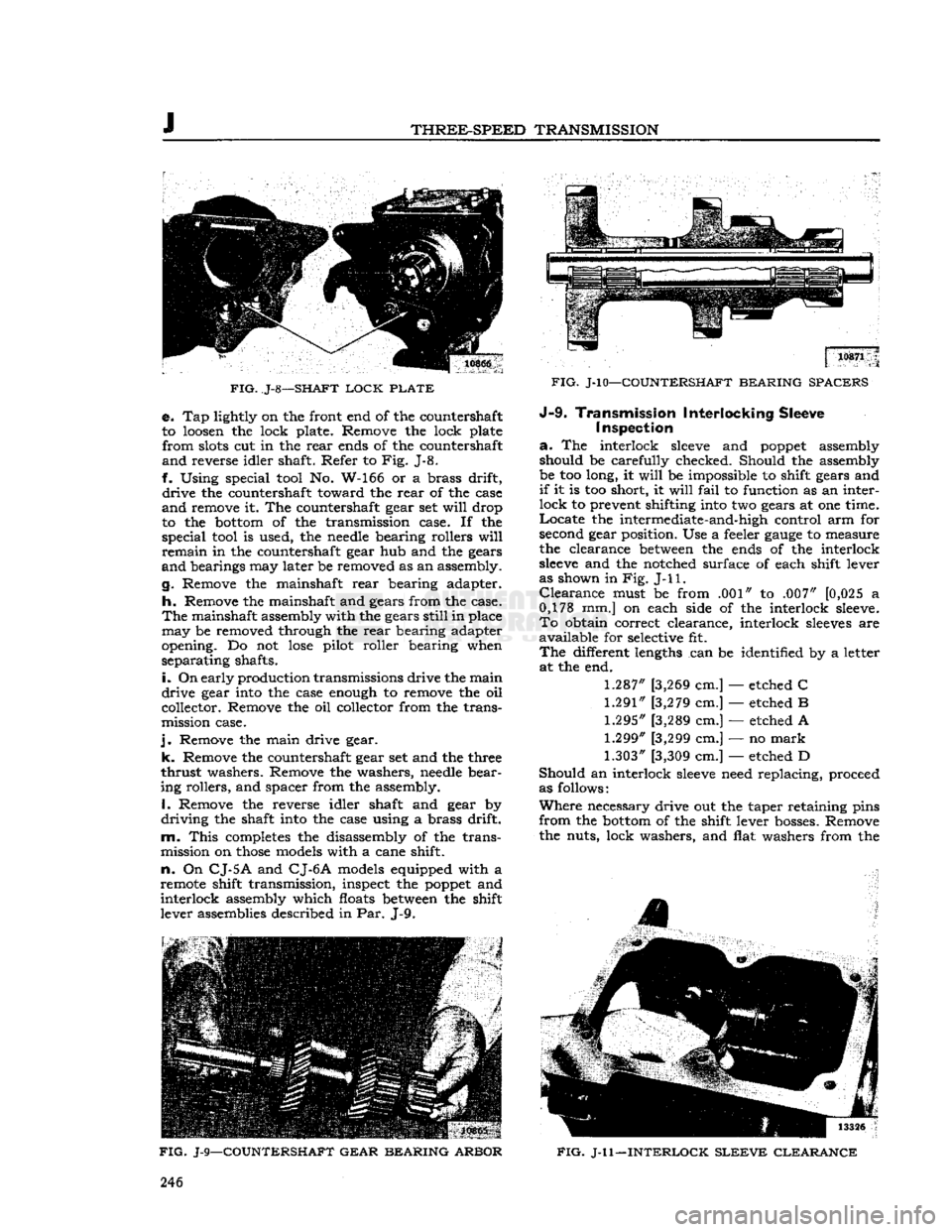
FIG.
J-8—SHAFT
LOCK
PLATE
e. Tap lightly on the front end of the countershaft
to loosen the lock plate. Remove the lock plate
from
slots cut in the
rear
ends of the countershaft
and
reverse idler shaft. Refer to Fig. J-8.
f. Using special tool No. W-166 or a brass drift,
drive
the countershaft toward the
rear
of the case
and
remove it. The countershaft gear set
will
drop
to the bottom of the transmission case. If the
special
tool is used, the needle bearing rollers
will
remain
in the countershaft gear hub and the gears
and
bearings may later be removed as an assembly.
g. Remove the mainshaft
rear
bearing adapter.
h.
Remove the mainshaft and gears from the case.
The
mainshaft assembly with the gears
still
in place
may
be removed through the
rear
bearing adapter
opening. Do not
lose
pilot roller bearing when
separating
shafts.
i.
On
early production transmissions drive the main
drive
gear into the case enough to remove the oil
collector. Remove the oil collector from the trans
mission case.
j.
Remove the main drive gear,
k.
Remove the countershaft gear set and the three
thrust
washers. Remove the washers, needle bear
ing rollers, and spacer from the assembly. 1, Remove the reverse idler shaft and gear by
driving
the shaft into the case using a brass drift,
m.
This
completes the disassembly of the trans
mission on
those
models with a cane shift,
n.
On
CJ-5
A
and
CJ-6 A
models equipped with a
remote shift transmission, inspect the poppet and
interlock
assembly which floats between the shift
lever assemblies described in Par. J-9.
FIG.
J-9—COUNTERSHAFT GEAR BEARING ARBOR
FIG.
J-l0—COUNTERSHAFT BEARING SPACERS J-9-
Transmission Interlocking Sleeve
I
inspection
a.
The interlock
sleeve
and poppet assembly should be carefully checked. Should the assembly
be too long, it
will
be impossible to shift gears and
if
it is too short, it
will
fail
to function as an inter
lock
to prevent shifting into two gears at one time.
Locate
the intermediate-and-high control arm for
second gear position. Use a feeler
gauge
to measure
the clearance between the ends of the interlock
sleeve
and the notched surface of each shift lever
as shown in Fig.
J-l
1.
Clearance
must be from .001" to .007" [0,025 a
0,178 mm.] on each side of the interlock sleeve.
To
obtain correct clearance, interlock
sleeves
are
available
for selective fit.
The
different lengths can be identified by a letter at the end.
1.287"
[3,269 cm.] — etched C
1.291"
[3,279 cm.] — etched B
1.295"
[3,289 cm.] — etched A
1.299"
[3,299 cm.] — no
mark
1.303"
[3,309 cm.] — etched D
Should
an interlock
sleeve
need replacing, proceed
as follows:
Where
necessary drive out the taper retaining pins
from
the bottom of the shift lever bosses. Remove
the nuts, lock washers, and flat washers from the
4
FIG.
J-l 1—INTERLOCK
SLEEVE
CLEARANCE
246
Page 257 of 376
'Jeep*
UNIVERSAL
SERIES
SERVICE
MANUAL
J J-20
TRANSMISSION
SERVICE
DIAGNOSIS
SYMPTOMS
PROBABLE
REMEDY
Lock
in Two
Gears
Replace
Poppet
or Shift Levers
Slips
Out of High Gear Transmission Misaligned with Bellhousing
End
Play in Main Drive Gear Damaged Pilot Bearing or Front Bearing.
Slips
Out of Second
Worn
Gear Replace
Weak
Poppet
Spring Replace
Noise
in Low Gear
Gear
Teeth Worn Replace Gears
Shifting
Shoe
Bent Replace
Shoe
Lack
of Lubrication Drain and Refill
Grease
Leak into Bellhousing Gasket Broken Front Bearing Retainer Replace
Transmission Main Drive Gear Oil Seal Replace Align Transmission Case to Bellhousing
and Bellhousing to Engine
Tighten Front Retainer
Replace
J-21.
TRANSMISSION
SPECIFICATIONS
HURRICANE
F4
ENGINE
3-SPEED
Vehicle:
CJ-3B,
CJ-5,
CJ-5A,
CJ-6,
CJ-6A
DJ-5,
DJ-6
Make
Type
Speeds
Ratios: —
First
Second
Third
Fourth
Warner
T90C
Synchronous Mesh
3 Forward — 1 Reverse
3.339
to 1 1.551 to 1 1.000 to 1
Warner
T96
Synchronous Mesh
3 Forward — 1 Reverse
2.605
to 1 1.630 to 1
1.000 to 1
Reverse
Interlock
Poppet
Clearance. . .
3.798
to 1
3.536
to 1
.001" to .007"
[0,025
a 0,178 mmJ
DAUNTLESS
V-6
ENGINE
3-SPEED
Vehicle:
CJ-5,
CJ-6,
CJ-5A,
CJ-6A
DJ-5,
DJ-6
Late
CJ-5, CJ-6
Make
Warner
Warner Warner
Model
AS7
T86AA
AS9
T86AA
T14A
Type..
Synchromesh
Synchromesh Synchromesh
Speeds
3 Forward — 1 Reverse 3 Forward — 1 Reverse 3 Forward — 1 Reverse
Ratios: —
First
2.798
to 1
2.798
to 1
3.100 to 1
Second
1.687 to 1 1.687 to 1 1.612 to 1
Third
1.000 to 1
1.000 to 1 1.000 to 1
Reverse
3.798
to 1
3.798
to 1 3.100 to 1 257