ECO mode JEEP CJ 1953 User Guide
[x] Cancel search | Manufacturer: JEEP, Model Year: 1953, Model line: CJ, Model: JEEP CJ 1953Pages: 376, PDF Size: 19.96 MB
Page 129 of 376
'Jeep9
UNIVERSAL
SERIES
SERVICE
MANUAL
E-59.
Fuel
Pump Installation
a.
Make certain mating surfaces of fuel pump and
engine
cylinder case are clean. Cement a new gasket
to mounting
flange
of fuel pump.
b. Position fuel pump on cylinder block, so that
cam
lever of pump rests on fuel pump cam of cam
shaft. Secure pump to block with two cap screws
and
lock washers.
c. Connect intake and
outlet
fuel lines to fuel
pump.
E-60.
FUEL
PUMP
(SINGLE-ACTION)
—
HURRICANE
F4
ENGINE
•
Late
Models.
The
Hurricane F4
engine
is equipped with a single-
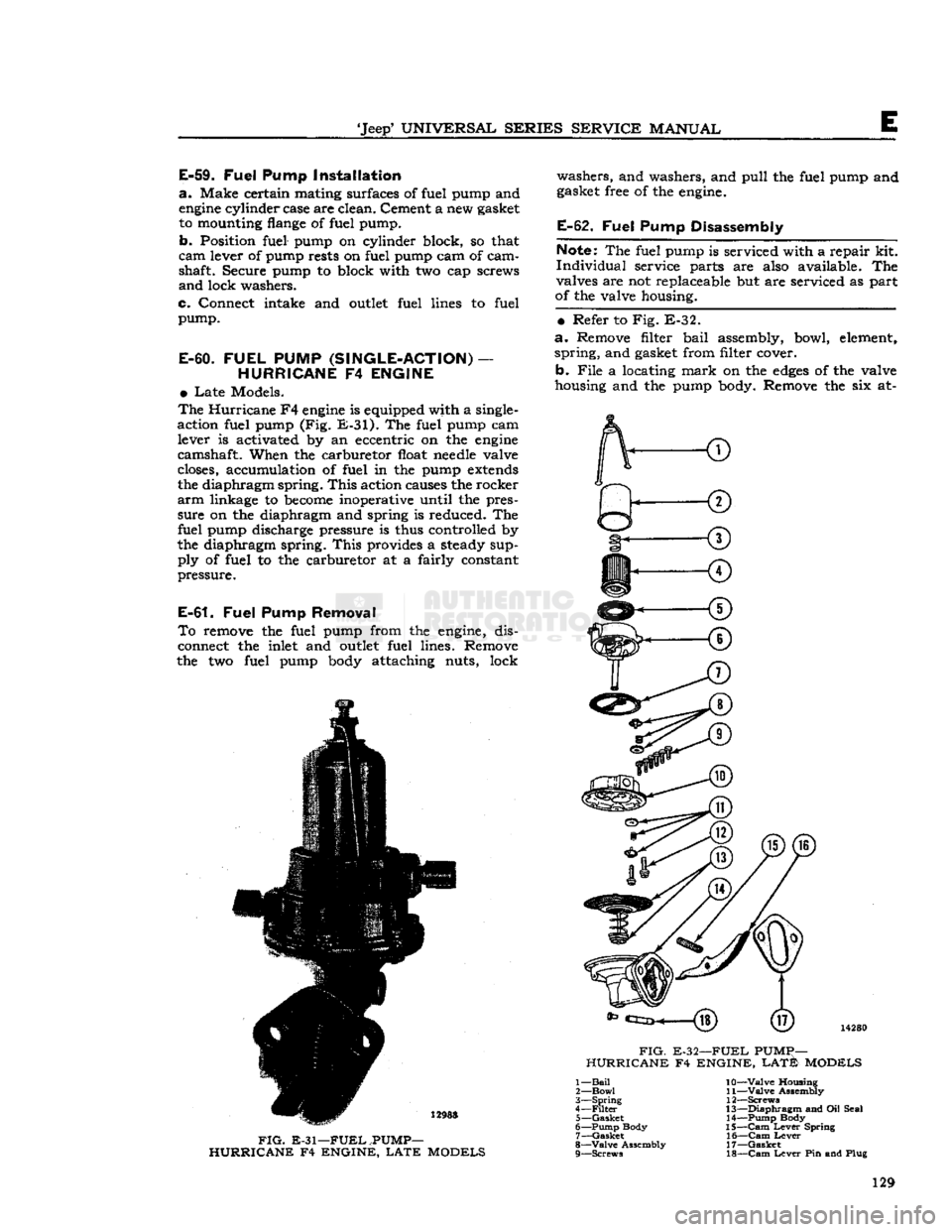
action fuel pump (Fig.
E-31).
The fuel pump cam lever is activated by an eccentric on the
engine
camshaft. When the carburetor float
needle
valve
closes, accumulation of fuel in the pump
extends
the diaphragm spring.
This
action causes the rocker
arm
linkage to
become
inoperative until the pres
sure on the diaphragm and spring is reduced. The fuel pump discharge pressure is thus controlled by
the diaphragm spring.
This
provides a steady sup ply of fuel to the carburetor at a fairly constant
pressure.
E-61.
Fuel
Pump Removal
To
remove the fuel pump from the
engine,
dis
connect the inlet and
outlet
fuel lines. Remove
the two fuel pump
body
attaching nuts, lock washers, and washers, and pull the fuel pump and
gasket free of the
engine.
E-62.
Fuel
Pump Disassembly
Note:
The fuel pump is serviced with a repair kit.
Individual
service parts are also available. The
valves are not replaceable but are serviced as part
of the valve housing.
•
Refer to Fig. E-32.
a.
Remove filter bail assembly, bowl,
element,
spring,
and gasket from filter cover. b.
File
a locating
mark
on the
edges
of the valve
housing and the pump body. Remove the six at-
14280
FIG.
E-32—FUEL
PUMp—
HURRICANE F4 ENGINE,
LATE
MODELS
12988
FIG.
E-31—FUEL
.PUMP-
HURRICANE F4 ENGINE,
LATE
MODELS 1—
Bail
2—
Bowl
3—
Spring
4—
Filter
5—
Gasket
6— Pump Body 7—
Gasket
8—
Valve
Assembly 9— Screws 10—
Valve
Housing
11—
Valve
Assembly
12— Screws
13—
Diaphragm
and Oil Seal 14— Pump Body
15—
Cam
Lever
Spring 16—
Cam
Lever
17—
Gasket
18—
Cam
Lever
Pin and Plug 129
Page 131 of 376
'Jeep'
UNIVERSAL SERIES SERVICE
MANUAL
E
possibility of vapor lock by keeping cool fuel from
the tank constantly circulating through the fuel
pump.
Fuel
pump pressure at carburetor (inlet) on Daunt
less
V6-225
engine
should be 3% lbs.
[0,264
kgm-cm2] minimum at idle with the vapor return
hose
squeezed off. With the vapor return
hose
open
pump pressure should be 2j^ lbs. [0,176 kg-cm2]
minimum.
The
Dauntless V-6
engine
is equipped with a sealed
unit,
non-repairable, single-action fuel pump (Fig.
E-33).
Note:
All Dauntless V-6
engines
are equipped with
a
throw-away can-type gasoline filter installed in
the fuel line
between
the fuel pump and the
car
buretor.
This
unit must be replaced every
12,000
miles
[19.200
km.] of vehicle operation.
E-68.
Fuel
Pump Removal
To
remove the fuel pump from the Dauntless V-6
engine, disconnect the fuel inlet, fuel
outlet
and fuel return lines from the pump. Remove the two
fuel pump body attaching cap screws and lock
washers.
Pull
the fuel filter bracket free and remove the pump and gasket. Discard pump and gasket.
Install
new pump in reverse procedure of removal.
E-69.
AIR
CLEANER
Servicing
of the air cleaner is properly taken care of as part of the periodic lubrication and servicing of the vehicle. For this reason, air cleaner servicing
information is given in the Lubrication Section.
Refer
to and follow the instructions given there.
E-70. ACCELERATOR LINKAGE
The
accelerator linkage is properly adjusted when
the vehicle leaves the factory. However, in time
components parts
will
become
worn and require re
adjustment to maintain a smooth even control of
engine
speed. On Models equipped with F4
engines
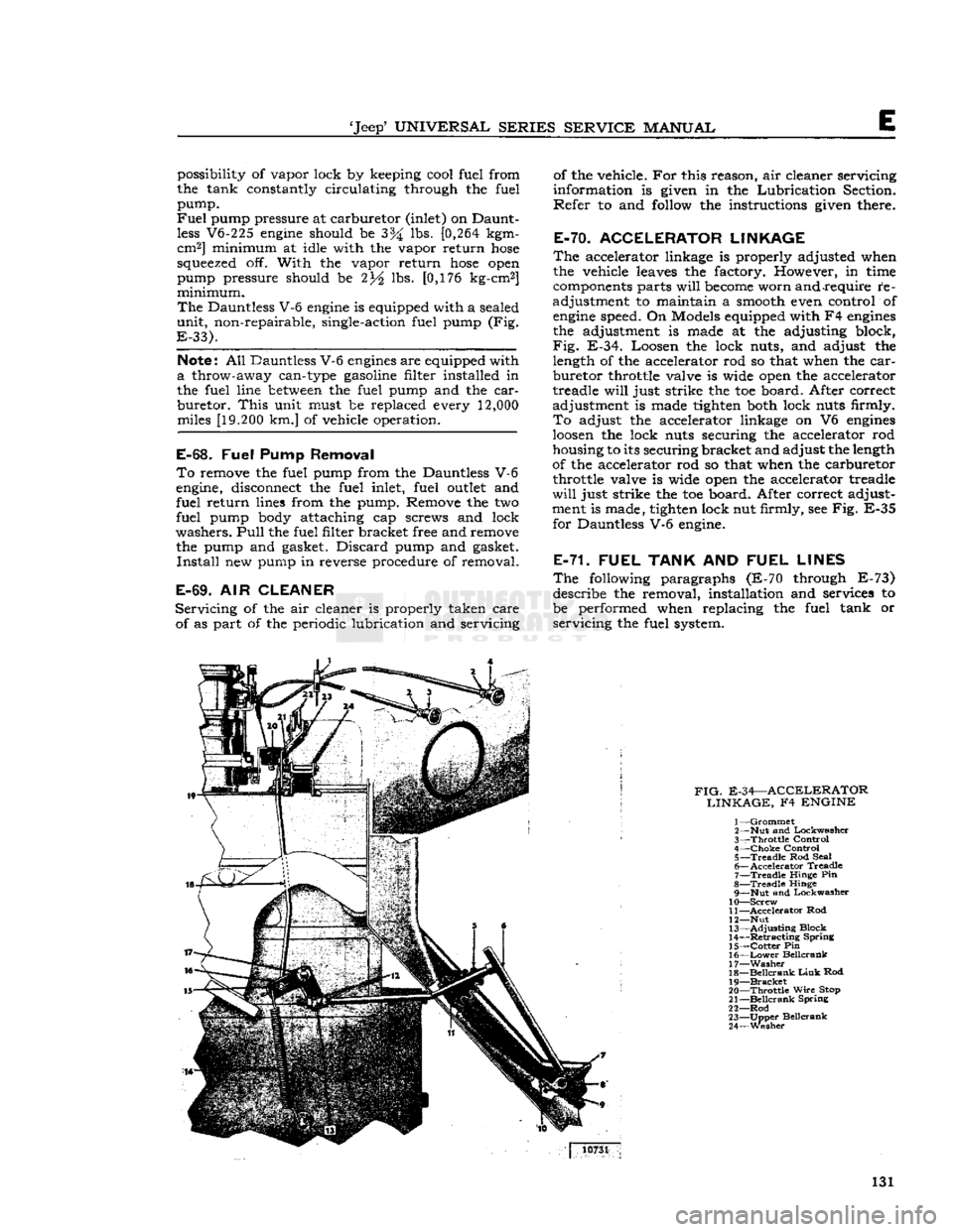
the adjustment is made at the adjusting block,
Fig.
E-34. Loosen the lock nuts, and adjust the length of the accelerator rod so that when the
car
buretor throttle valve is wide open the accelerator
treadle
will
just strike the toe board. After correct
adjustment is made tighten both lock nuts firmly.
To
adjust the accelerator linkage on V6
engines
loosen
the lock nuts securing the accelerator rod
housing to its securing bracket and adjust the length
of the accelerator rod so that when the carburetor throttle valve is wide open the accelerator treadle
will
just strike the toe board. After correct adjust
ment is made, tighten lock nut firmly, see Fig. E-35 for Dauntless V-6 engine.
E-71. FUEL
TANK
AND
FUEL LINES
The
following paragraphs (E-70 through E-73) describe the removal, installation and services to
be performed when replacing the fuel tank or
servicing
the fuel system.
FIG.
E-34—ACCELERATOR LINKAGE,
F4
ENGINE
1—
Grommet
2— Nut and Lockwasher
3—
Throttle
Control
4—
Choke
Control 5—
Treadle
Rod Seal
6—
Accelerator
Treadle
7—
Treadle
Hinge Pin
8—
Treadle
Hinge 9— Nut and Lockwasher
10—
Screw
11—
Accelerator
Rod
12— Nut
13—
Adjusting
Block
14—
Retracting
Spring
15—
Cotter
Pin
16—
Lower
Beilcrank
17—
Washer
18—
Beilcrank
Link
Rod
19—
Bracket
20—
Throttle
Wire
Stop
21—
Beilcrank
Spring
22—
Rod
23—
Upper
Beilcrank
24—
Wesher
10731
131
Page 144 of 376
Fl
EXHAUST EMISSION CONTROL SYSTEMS
12793
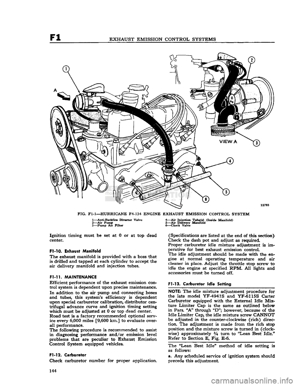
FIG.
Fl-1—HURRICANE
F4-134
ENGINE EXHAUST EMISSION CONTROL SYSTEM
1—
Anti-Backfire
Diverter
Valve
2— Air
Pump
3—
Pump
Air
Filter
Injection
Tube(s)
(Inside
Manifold)
5—Air
Delivery
Manifold
6—
Check
Valve
Ignition
timing must be set at 0 or at top dead
center.
Fl-10.
Exhaust Manifold
The
exhaust manifold is provided with a
boss
that is drilled and tapped at each cylinder to accept the
air
delivery manifold and injection tubes.
Fl-11.
MAINTENANCE
Efficient
performance of the exhaust emission con
trol
system is dependent upon precise maintenance.
In
addition to the air pump and connecting
hoses
and
tubes, this system's efficiency is dependent
upon special carburetor calibration, distributor cen
trifugal
advance curve and ignition timing setting
which
must be adjusted at 0 or top dead center.
Road
test
is a factory recommended optional serv ice every
6,000
miles
[9,600
km.] to evaluate over
all
performance.
The
following procedure is recommended to assist
in
diagnosing performance and/or emission level
problems that are peculiar to
Exhaust
Emission
Control
System equipped vehicles.
Fl-12.
Carburetor
Check
carburetor number for proper application. (Specifications are listed at the end of this section)
Check
the dash pot and adjust as required.
Proper
carburetor idle mixture adjustment is im
perative for
best
exhaust emission control.
The
idle adjustment should be made with the en
gine
at normal operating temperature and air
cleaner
in place. Adjust the throttle
stop
screw to
idle the
engine
at specified RPM. All lights and accessories must be turned off.
Fl-13.
Carburetor
Idle
Setting
NOTE:
The idle mixture adjustment procedure for
the late model
YF-4941S
and
YF-6115S
Carter
Carburetor
equipped with the
External
Idle
Mix
ture
Limiter
Cap is the same as outlined below
in
Pars.
"A"
through
"D";
however, because of the
Idle
Limiter
Cap,
the idle mixture screw
CANNOT
be adjusted in the counter-clockwise
(rich)
direc
tion. The adjustment is made from the
rich
stop
position and the mixture screw is turned in (clock
wise) approximately %
turn
to "Lean Best
Idle."
Refer
to Section E, Fig. E-6.
The
"Lean
Best
Idle"
method of idle setting is as follows:
a.
Any scheduled service of ignition system should
precede this adjustment. 144
Page 147 of 376
'Jeep'
UNIVERSAL SERIES
SERVICE
MANUAL
Fl
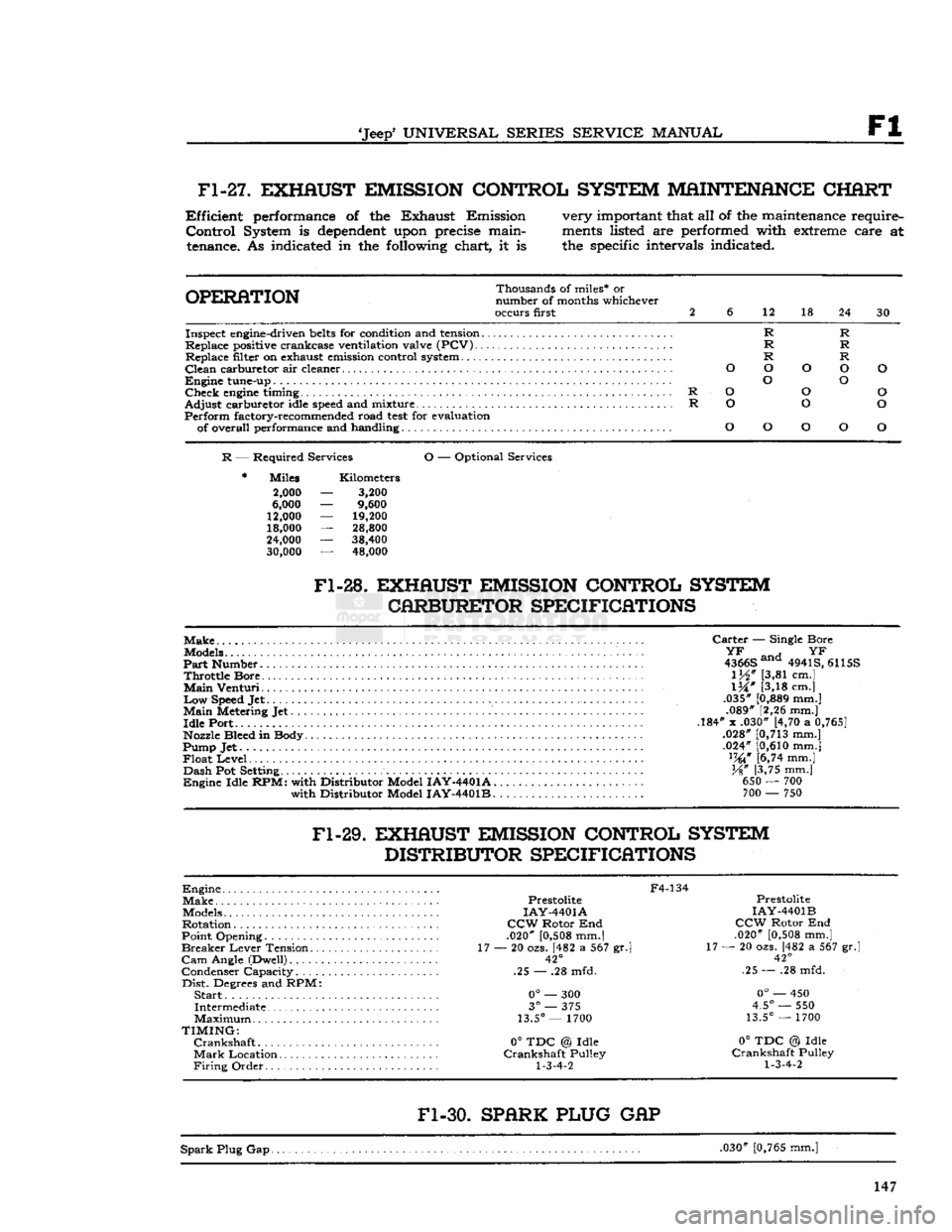
Fl-27.
EXHAUST EMISSION CONTROL SYSTEM MAINTENANCE CHART
Efficient
performance of the Exhaust Emission
Control
System is
dependent
upon precise maintenance. As indicated in the following chart, it is very important that all of the maintenance require
ments
listed are performed with extreme care at
the specific intervals indicated.
OPERATION
Thousands of miles* or
number of months whichever
occurs first 2
6
12 18
24 30
R R
R R
R R
O O o O
O
o O
R
O
o
o
R
o
o o
o
o
o
O
o
Inspect engine-driven
belts
for condition and tension...
Replace positive crankcase ventilation valve (PCV) Replace filter on exhaust emission control system
Clean
carburetor air cleaner
Engine
tune-up
Check
engine
timing
Adjust
carburetor idle
speed
and mixture
Perform
factory-recommended road
test
for evaluation of overall performance and handling
R
— Required Services
O
— Optional Services
Miles
2,000
6,000
12,000
18,000
24,000
30,000
Kilometers
3,200
9,600
19,200
28,800
38,400 48,000
Fl-28.
EXHAUST EMISSION CONTROL SYSTEM CARBURETOR SPECIFICATIONS
Make
Models
Part
Number
Throttle
Bore
Main
Venturi
Low
Speed Jet
Main
Metering Jet
Idle
Port
Nozzle Bleed in Body
Pump Jet
Float
Level
Dash
Pot Setting
Engine
Idle
RPM:
with Distributor Model
IAY-4401A.
with Distributor Model
IAY-4401B.
Carter
— Single Bore
^ an H
YF
4366S ana 4941S, 6115S
1M"
[3,81 cm.]
IX"
[3,18 cm.]
.035"
[0,889
mm.] .089" [2,26 mm.]
.184" x .030" [4,70 a
0,765]
.028"
[0,713
mm.]
.024"
[0,610
mm.] lW [6,74 mm.]
%"
[3,75 mm.] 650 — 700 700 — 750
Fl-29.
EXHAUST EMISSION CONTROL SYSTEM DISTRIBUTOR SPECIFICATIONS
Engine
Make
Models
Rotation
Point Opening
Breaker
Lever
Tension..
Cam
Angle (Dwell)
Condenser Capacity
Dist.
Degrees and RPM:
Start..
Intermediate
Maximum
TIMING:
Crankshaft
Mark
Location
Firing
Order
F4-134
Prestolite
IAY-4401A
CCW
Rotor End
.020"
[0,508
mm.|
17 — 20 ozs. [482 a 567 gr.l
42°
.25 — .28 mfd.
0°
— 300
3°
— 375
13.5°
— 1700
0°
TDC @ Idle
Crankshaft
Pulley
1-3-4-2
Prestolite
IAY-4401B
CCW
Rotor End
.020"
[0,508
mm.]
17 — 20 ozs. [482 a 567 gr.
42°
.25 — .28 mfd.
0°
— 450
4.5°
— 550
13.5°
— 1700
0°
TDC @ Idle
Crankshaft
Pulley
1-3-4-2
Fl-30.
SPARK PLUG
GAP
Spark
Plug Gap. .030"
[0,765
mm.] 147
Page 148 of 376
Fl
EXHAUST
EMISSION
CONTROL
SYSTEMS
IMPORTANT
NOTICE
The
Exhaust
Emission Systems covered
in
this publication
meet
State and
Federal
requirements for hydrocarbon and carbon
monoxide
emissions.
To
assure continued proper operation,
these
systems
must
be
inspected
regularly,
parts must be replaced
at
factory-recommended intervals and
engine
tune-up services performed at intervals specified in the
Exhaust
Emission
Con
trol
System Maintenance charts.
For
the
above
reasons,
these
systems
must not, under any circumstances,
be
altered
to anything other than
required
specifications provided in this publication.
Further,
the
Exhaust
Emission
Control
System, or any
of
its components, must
not be physically altered or modified in any respect.
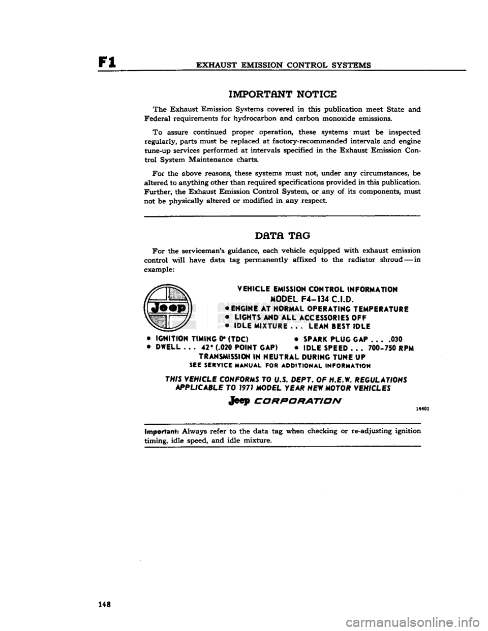
DHTfl
TAG
For
the serviceman's guidance, each vehicle equipped with exhaust emission
control
will
have data
tag
permanently affixed
to the
radiator shroud—-in
example:
VEHICLE
EMISSION
CONTROL
INFORMATION
MODEL
F4-134
C.I.D.
•
ENGINE
AT
NORMAL
OPERATING
TEMPERATURE
•
LIGHTS
AND
ALL
ACCESSORIES OFF
•
IDLE
MIXTURE
. . .
LEAN
BEST
IDLE
•
IGNITION
TIMING
0*
(TDC)
•
SPARK
PLUG
GAP
. . . .030
•
DWELL
...
42* (.020
POINT
GAP)
•
IDLE
SPEED
. . .
700-750 RPM
TRANSMISSION
IN
NEUTRAL
DURING
TUNE
UP
SEE SERVICE MANUAL
FOR
ADDITIONAL INFORMATION
THIS VEHICLE CONFORMS
TO U.S.
DEPT.
OF
H.E.W.
REGULATIONS APPLICABLE
TO
1971 MODEL YEAR NEW MOTOR VEHICLES
Jeep
CORPORATION
14401
Important:
Always refer
to
the data tag when checking or re-adjusting ignition
timing,
idle speed, and idle mixture. 148
Page 158 of 376
F2
EXHAUST EMISSION CONTROL SYSTEMS
F2-3L
EXHAUST EMISSION CONTROL SYSTEM
DIAGNOSIS
GUIDE
Pump Noisy
Hoses Touching Other Parts of Engine or Body (Hood).
Note:
The Air Pump is not completely noiseless.
Under
normal conditions, pump
noise
rises in pitch as
engine
speed
increases. It is desirable to allow
for normal break-in wear of the pump prior to re
placement for
excessive
noise.
Pump Seized
Replace pump.
-
do not pry on housing.
Leak
In Hose
Check
for leaks; using
soap
and water, tighten clamps or replace
hoses.
Pump Inoperative
Loose Belt — tighten belt
-
Filter
Plugged — replace.
Exhaust
Backfire
Check
for vacuum leaks — correct as necessary.
Check
anti-backfire valve — replace as necessary
Induction System Backfire
Verify
engine
timing and distributor dwell.
Verify
accelerator pump charge.
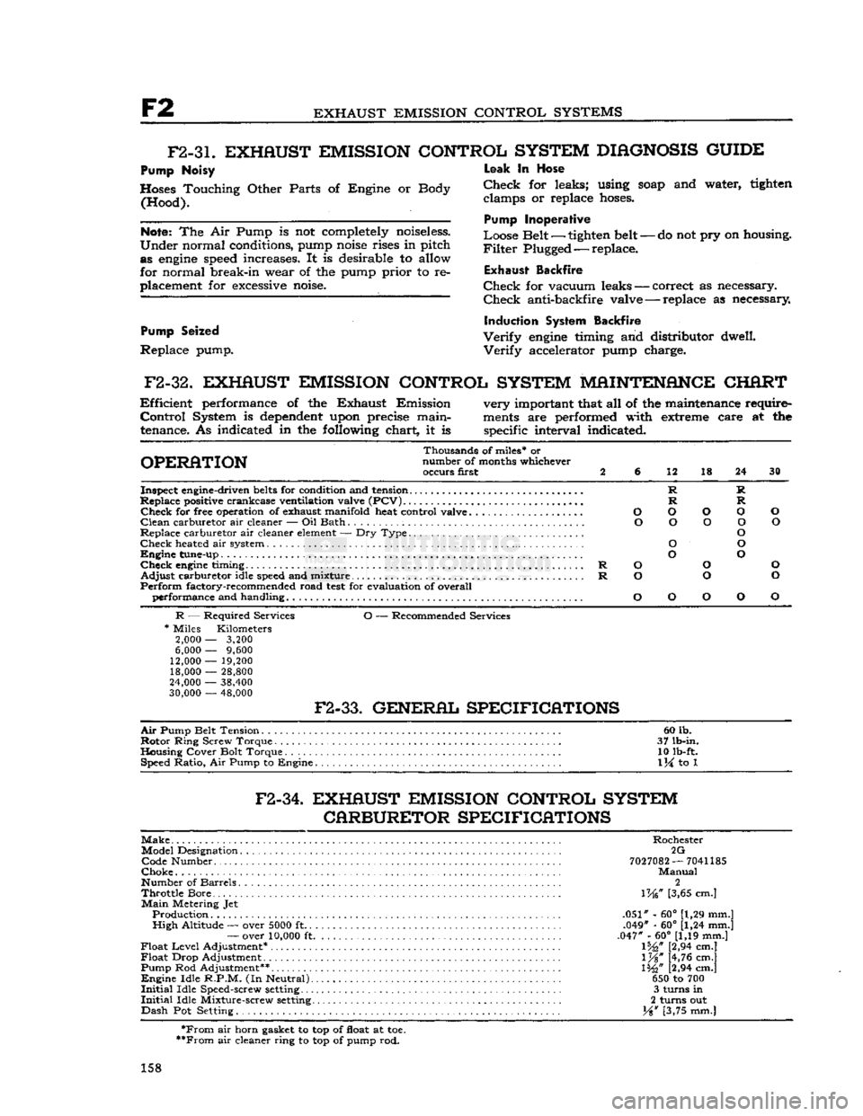
F2-32.
EXHAUST EMISSION CONTROL SYSTEM MAINTENANCE CHART
Efficient
performance of the Exhaust Emission very important that all of the maintenance require-
Control
System is
dependent
upon precise main-
ments
are performed with extreme care at the
tenance. As indicated in the following chart, it is specific interval indicated.
Thousands of miles* or
OPERATION
number of months whichever occurs first 2 6 12 18 24 30
Inspect engine-driven
belts
for condition and tension R R
Replace positive crankcase ventilation valve
(PCV)
R R
Check
for free operation of exhaust manifold heat control valve O O O O O
Clean
carburetor air cleaner — Oil Bath O O O O O
Replace carburetor air cleaner
element
— Dry Type O
Check
heated air system O O
Engine
tune-up O O
Check
engine
timing R O O O
Adjust
carburetor idle
speed
and mixture R O O O
Perform
factory-recommended road
test
for evaluation of overall performance and handling O O O O O
R
— Required Services O — Recommended Services
*
Miles Kilometers
2,000
—
3,200
6,000
—
9,600
12,000
—
19,200 18,000
—
28,800
24,000
—
38,400
30,000
—
48,000
F2-33.
GENERAL SPECIFICATIONS
Air
Pump Belt Tension 60 lb.
Rotor
Ring Screw Torque . 37 lb-in.
Housing Cover Bolt Torque 10 lb-ft. Speed Ratio, Air Pump to Engine
1
\i to 1
F2-34.
EXHAUST EMISSION CONTROL SYSTEM CARBURETOR SPECIFICATIONS
Make
Rochester Model Designation 2G Code Number
7027082
—
7041185
Choke
Manual
Number of Barrels 2
Throttle
Bore... \W [3,65 cm.]
Main
Metering Jet Production .051" - 60° [1,29 mm.]
High
Altitude — over
5000
ft .049" - 60° [1,24 mm.]
—
over
10,000
ft .047" - 60° [1,19 mm.]
Float
Level
Adjustment* 1%," [2,94 cm.]
Float
Drop Adjustment l%" [4,76 cm.]
Pump Rod Adjustment** 1%" [2,94 cm.]
Engine
Idle
R.P.M.
(In Neutral) 650 to 700
Initial
Idle Speed-screw
setting
3 turns in
Initial
Idle Mixture-screw
setting
2 turns out
Dash
Pot Setting. Y%w [3,75 mm.]
*From
air horn gasket to top of float at toe.
**From
air cleaner ring to top of pump rod.
158
Page 159 of 376
'Jeep'
UNIVERSAL SERIES SERVICE
MANUAL
F2
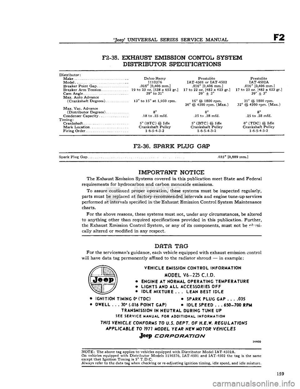
F2-35.
EXHAUST EMISSION CONTOL SYSTEM
DISTRIBUTOR SPECIFICATIONS
Distributor:
Make
Delco-Remy Prestolite Prestolite
Model...
1110376
IAT-4501 or IAT-4502 IAT-4502A
Breaker
Point Gap .016"
[0,406
mm.] .016"
[0,406
mm.] .016"
[0,406
mm.]
Breaker
Arm Tension 19 to 23 oz. [538 a 652 gr.] 17 to 22 oz. [482 a 623 gr.] 17 to 22 oz. [482 a 623 gr.]
Cam
Angle. 29° to 31° 29° + 3° 29° ± 3°
Max.
Auto Advance
(Crankshaft
Degrees). 13° to 15° at 1,950 rpm. 16° (& 1800 rpm. 21° @ 1800 rpm.
26°
@
4200
rpm. (Max.) 32° @
4200
rpm. (Max.)
Max.
Vac. Advance
(Distributor
Degrees) 8° 8° 8°
Condenser Capacity. .18 to .23 mfd. .25 to .28 mfd. .25 to .28 mfd.
Timing:
Crankshaft
5°
(BTC)
@ Idle 5°
(BTC)
© Idle 0°
(TDC)
© Idle
Mark
Location Crankshaft Pulley Crankshaft Pulley Crankshaft Pulley
Firing
Order
1-6-5-4-3-2 1-6-5-4-3-2 1-6-5-4-3-2
F2-36.
SPARK PLUG
GAP
Spark
Plug Gap. .035"
[0,889
mm.]
IMPORTANT
NOTICE
The
Exhaust Emission Systems covered in this publication
meet
State and Federal
requirements for hydrocarbon and carbon
monoxide
emissions.
To
assure continued proper operation,
these
systems
must be inspected regularly,
parts must be replaced at factory-recommended intervals and
engine
tune-up services
performed at intervals specified in the Exhaust Emission Control System Maintenance
charts.
For
the
above
reasons,
these
systems
must not, under any circumstances, be altered
to anything other than required specifications provided in this publication.
Further,
the Exhaust Emission Control System, or any of its components, must not be physi
cally
altered or modified in any respect.
DATA
TAG
For
the serviceman's guidance, each vehicle equipped with exhaust emission control
will
have data tag permanently affixed to the radiator shroud — in example:
VEHICLE EMISSION CONTROL INFORMATION MODEL V6-225 C.I.D.
•
ENGINE
AT
NORMAL OPERATING TEMPERATURE
•
LIGHTS
AND ALL
ACCESSORIES
OFF
•
IDLE MIXTURE
.. .
LEAN BEST IDLE
•
IGNITION TIMING
0*
(TDC)
*
SPARK PLUG
GAP 035
•
DWELL
. . . 30* (.016
POINT
GAP) •
IDLE SPEED
. . .
650- 700
RPM
TRANSMISSION
IN
NEUTRAL DURING TUNE
UP
SEE
SERVICE MANUAL FOR ADDITIONAL INFORMATION
THIS VEHICLE CONFORMS
TO U.S. DEPT. OF H.E.W.
REGULATIONS APPLICABLE
TO
1971
MODEL YEAR
NEW
MOTOR VEHICLES
Jeep
CORPORATION
14400
NOTE:
The
above
tag applies to vehicles equipped with Distributor Model
IAT-4502A.
On
vehicles equipped with Distributor Models
1110376,
IAT-4501 and IAT-4502 the tag is the same
except
that Ignition Timing is 5°
T.D.C.
Always
refer to the data tag when checking or re-adjusting ignition timing, idle speed, and idle mixture.
159
Page 178 of 376
H
ELECTRICAL
SYSTEM
14365
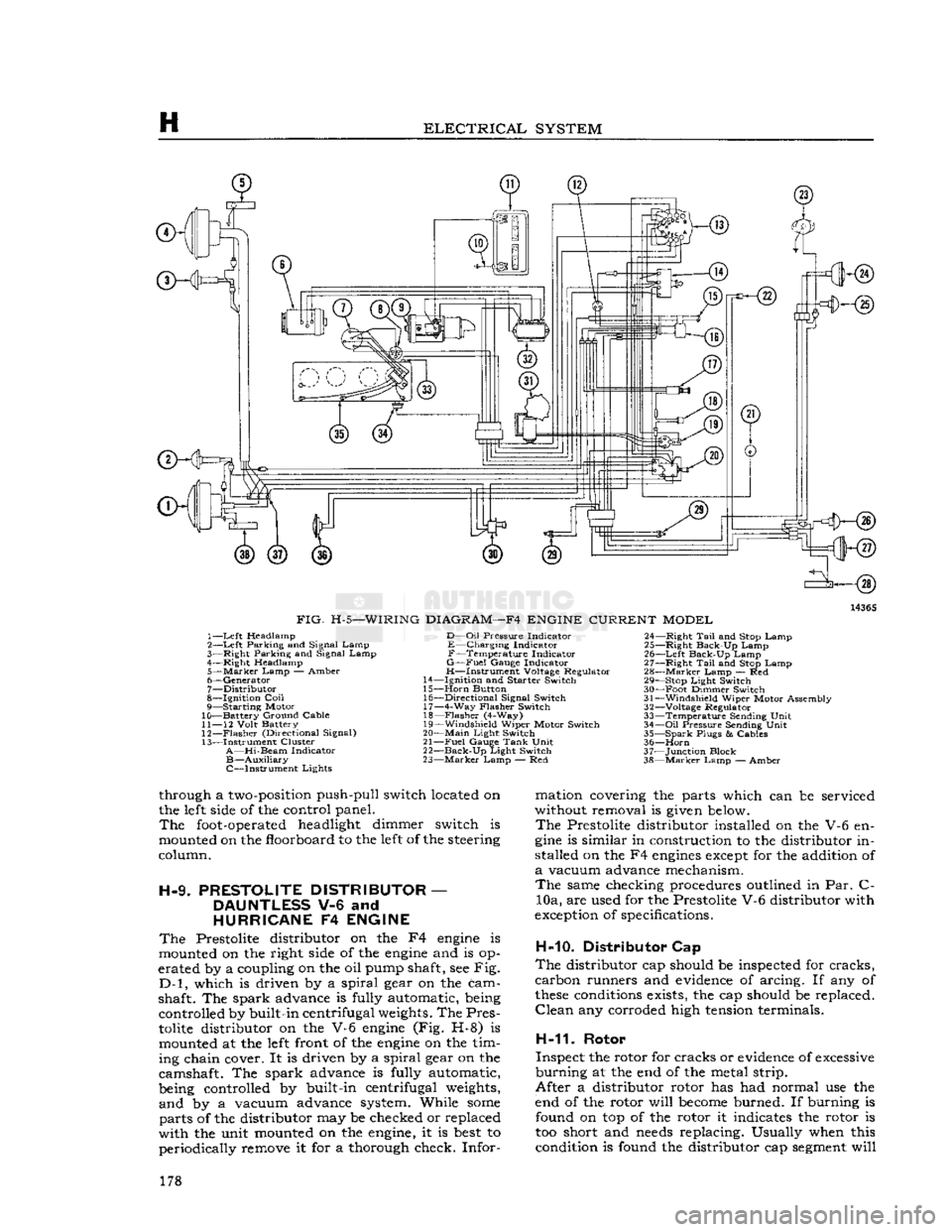
FIG.
H-5—WIRING
DIAGRAM—F4
ENGINE
CURRENT
MODEL
1—
Left
Headlamp
2—
Left
Parking and Signal Lamp
3—
Right
Parking and Signal Lamp
4—
Right
Headlamp
5—
Marker
Lamp
— Amber
6—
Generator
7—
Distributor
8—
Ignition
Coil
9— Starting Motor
10— Battery Ground Cable
11—
12
Volt
Battery
12—
Flasher
(Directional Signal)
13— Instrument Cluster
A—Hi-Beam
Indicator
B—Auxiliary
C—Instrument Lights
D—Oil
Pressure
Indicator
E—Charging Indicator
F—Temperature Indicator
G—Fuel
Gauge
Indicator
H—Instrument Voltage Regulator
14—
Ignition
and
Starter
Switch
15—
Horn
Button 16—
Directional
Signal Switch 17— 4-Way
Flasher
Switch
18—
Flasher
(4-Way)
19—
Windshield
Wiper Motor Switch
20—
Main
Light
Switch
21—
Fuel
Gauge
Tank
Unit
22—
Back-Up
Light
Switch
23—
Marker
Lamp — Red 24—
Right
Tail
and Stop Lamp
25—
Right
Back-Up Lamp
26—
Left
Back-Up Lamp
27—
Right
Tail
and Stop Lamp
28—
Marker
Lamp — Red 29— Stop
Light
Switch
30— Foot Dimmer Switch
31—
Windshield
Wiper Motor Assembly
32—
Voltage Regulator
33— Temperature Sending
Unit
34—
Oil
Pressure
Sending
Unit
35— Spark
Plugs
&
Cables
36—
Horn
37— Junction Block
38—
Marker
Lamp — Amber
through a
two-position
push-pull switch located on
the
left
side
of the control panel.
The
foot-operated
headlight dimmer switch is
mounted on the floorboard to the
left
of the steering
column.
H-9.
PRESTOLITE
DISTRIBUTOR
—
DAUNTLESS
V-6 and
HURRICANE
F4
ENGINE
The
Prestolite distributor on the F4
engine
is
mounted on the right
side
of the
engine
and is op
erated by a coupling on the oil pump shaft, see Fig.
D-l,
which is driven by a spiral gear on the cam
shaft. The spark advance is fully automatic, being controlled by built-in centrifugal
weights.
The Pres
tolite
distributor on the V-6
engine
(Fig. H-8) is mounted at the
left
front of the
engine
on the tim
ing chain cover. It is driven by a spiral gear on the
camshaft. The spark advance is fully automatic,
being controlled by built-in centrifugal
weights,
and by a vacuum advance system. While
some
parts of the distributor may be checked or replaced
with the unit mounted on the
engine,
it is
best
to periodically remove it for a thorough check. Infor mation covering the parts which can be serviced
without removal is
given
below.
The
Prestolite distributor installed on the V-6 en
gine
is similar in construction to the distributor in
stalled on the F4
engines
except
for the addition of
a
vacuum advance mechanism.
The
same checking procedures outlined in Par. C- 10a, are used for the Prestolite V-6 distributor with
exception
of specifications.
H-10. Distributor Cap
The
distributor cap should be inspected for cracks,
carbon runners and
evidence
of arcing. If any of
these
conditions
exists, the cap should be replaced.
Clean
any corroded high
tension
terminals.
H-11.
Rotor
Inspect the rotor for cracks or
evidence
of
excessive
burning at the end of the metal strip.
After a distributor rotor has had normal use the
end of the rotor will
become
burned. If burning is found on top of the rotor it indicates the rotor is
too short and
needs
replacing. Usually when this condition is found the distributor cap
segment
will 178
Page 188 of 376
H
ELECTRICAL
SYSTEM
colder plug may be desirable. However, under- or
over-heating is usually caused by factors other than the type of
spark
plugs and the cause should be determined before changing plugs. The design of the
engine
calls for plugs equivalent to Champion
J-8
for F4
engines
and
A.C.
44S or
UJ12Y
Champ
ion for the V6 engines, (as installed in production)
though any factor that consistently affects
engine
operating temperature may cause this requirement
to change. Overheating may be caused by in sufficient tightening of the plug in the head, which interferes with the flow of heat away from the firing
tip.
If this is the case, the plug gasket
will
show very
little flattening. Over-tightening, in
turn,
will
pro duce too easy a heat flow path and result in cold
plug operation.
This
will
be evident by excessive
flattening
and
deformation of the gasket.
Prevailing
temperatures, condition of the cooling system, and
air-fuel
mixture can affect the
engine
operating temperature and should be taken into consideration.
H-34.
GENERATOR
— F4
ENGINE
The
generator is an air-cooled, two-brush unit
which
cannot be adjusted to increase or decrease output. For replacement,
voltage
regulator and generator must be matched for
voltage
and capa
city,
polarity, and common source of manufacture.
Otherwise,
either a
loss
of ampere capacity or a
burned
out generator
will
result. Generators for
these
vehicles are 12-volt. Par. H-l explains the 12-volt system. Refer to the specifications at the
end of this section for information on correct generator rating for a specific model series.
The
circuit
breaker,
voltage
regulator, and current-
limiting
regulator are built into one combination
unit.
Because the regulator and battery are part
of the generator
circuit,
the output of the generator
depends upon the
state
of charge and temperature
of the battery.
With
a discharged battery, the
output
will
be high, decreasing proportionally as the battery
becomes
charged. For service informa
tion covering current regulator see Par. H-41.
H-36.
Generator
Maintenance
A
periodic inspection should be made of the charg
ing
circuit,
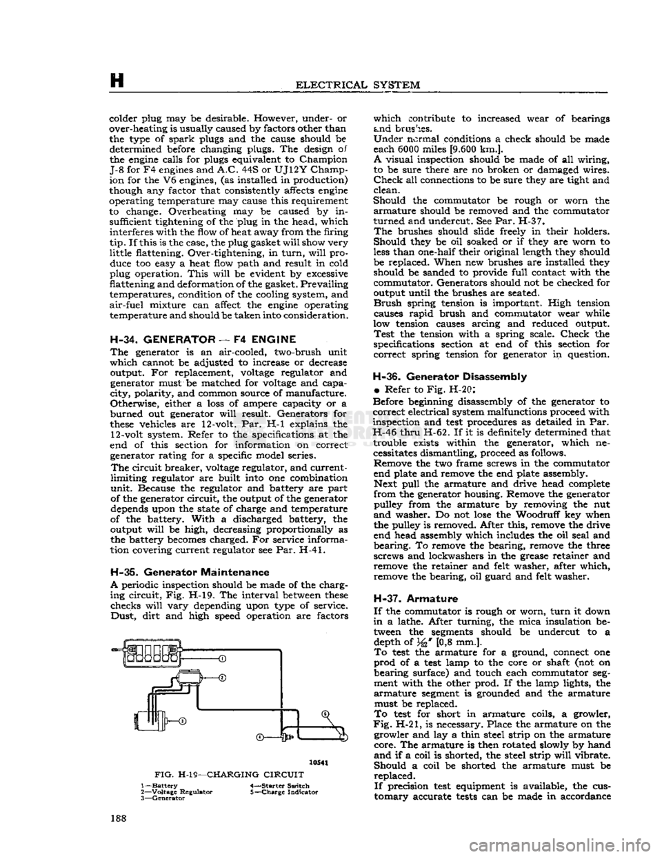
Fig. H-l9. The interval
between
these
checks
will
vary
depending upon type of service.
Dust,
dirt
and high speed operation are factors 10541
FIG.
H-19—CHARGING
CIRCUIT
1—
Battery
4-—Starter Switch
2—
Voltage
Regulator 5-—Charge Indicator
3—
Generator
which
contribute to increased wear of bearings
and
brushes.
Under
normal conditions a check should be made
each 6000 miles
[9.600
km.].
A
visual inspection should be made of all wiring,
to be sure there are no broken or damaged wires.
Check
all connections to be sure they are tight and
clean.
Should
the commutator be rough or worn the
armature
should be removed and the commutator
turned
and undercut. See Par. H-37.
The
brushes should slide freely in their holders.
Should
they be oil soaked or if they are worn to
less
than one-half their original length they should
be replaced. When new brushes are installed they should be sanded to provide
full
contact with the
commutator. Generators should not be checked for
output until the brushes are seated.
Brush
spring tension is important. High tension causes
rapid
brush and commutator wear while
low tension causes arcing and reduced output.
Test
the tension with a spring scale.
Check
the
specifications section at end of this section for
correct
spring tension for generator in question.
H-36.
Generator Disassembly
•
Refer to Fig. H-20:
Before beginning disassembly of the generator to
correct
electrical system malfunctions proceed with
inspection and
test
procedures as detailed in Par.
H-46
thru
H-62. If it is definitely determined that trouble exists within the generator, which necessitates dismantling, proceed as follows. Remove the two frame screws in the commutator
end plate and remove the end plate assembly. Next
pull
the armature and drive head complete
from
the generator housing. Remove the generator pulley from the armature by removing the nut
and
washer. Do not
lose
the Woodruff key when
the pulley is removed. After this, remove the drive
end head assembly which includes the oil seal and
bearing.
To remove the bearing, remove the three
screws and lockwashers in the grease retainer and remove the retainer and felt washer, after which,
remove the bearing, oil guard and felt washer.
H-37.
Armature
If
the commutator is rough or worn,
turn
it down
in
a lathe. After turning, the mica insulation be tween the
segments
should be undercut to a depth of 34* [0,8 mm.].
To
test
the armature for a ground, connect one
prod
of a
test
lamp to the core or shaft (not on
bearing
surface) and touch each commutator
seg
ment with the other prod. If the lamp lights, the
armature
segment
is grounded and the armature must be replaced.
To
test
for short in armature coils, a growler,
Fig.
H-21, is necessary. Place the armature on the growler and lay a thin steel strip on the armature
core.
The armature is then rotated slowly by hand
and
if a coil is shorted, the steel strip
will
vibrate.
Should
a coil be shorted the armature must be
replaced.
If
precision
test
equipment is available, the cus
tomary
accurate
tests
can be made in accordance 188
Page 195 of 376
'Jeep*
UNIVERSAL
SERIES SERVICE
MANUAL
H
no soldering or unsoldering of leads; two complete
rectifying
diode assemblies
which
eliminate the need
for removing and replacing individual diodes; a
corpplete isolation diode assembly; and a rotor
assembly complete with shaft,
pole
pieces, field
coil,
and slip rings.
The
transistorized
voltage
regulator is an electronic
switching device. It
senses
the
voltage
appearing
at the auxiliary terminal of the alternator and
supplies the necessary field current for maintaining
the system
voltage
at the output terminal. The
output current is determined by the battery electri
cal
load; such as headlights, heater, etc.
The
transistorized
voltage
regulator is a sealed
unit,
has no adjustments, and must be replaced
as a complete unit.
H-64. ALTERNATOR
PRECAUTIONS
The
following precautions must be observed to
prevent damage to the alternator and regulator.
a.
Never reverse battery connections. Always
check
the battery polarity with a voltmeter before
any
connections are made to be sure that all con
nections correspond to the battery ground polarity of the vehicle.
b.
Booster batteries for starting must be properly
connected. Make sure that the negative cable of
the booster battery is connected to the negative
terminal
of the battery in the vehicle. The positive
cable of the booster battery should be connected
to the positive terminal of the battery in the
vehicle.
c.
Disconnect the battery cables before using a fast charger.
d.
Never use a fast charger as a booster for
starting
the vehicle.
e.
Never disconnect the
voltage
regulator while
the
engine
is running.
f.
Do not ground the alternator output terminal.
g.
Do not operate the alternator on an open
circuit
with
the field energized.
h.
Do not attempt to polarize an alternator.
These
precautions are stated here as an aid to
service
personnel. They are also restated at appro
priate
places in the
text
of this section of the
manual.
H-65. ALTERNATOR
CHARGING
SYSTEM SERVICE
Important:
All alternator
tests
for the 35, 40 and
55 amp alternator are the same, however, there is a
difference
between
the location of the various ter
minals
and field current specifications. The field
current
of the 35 amp alternator should be 1.7 to 2.3 amps, 40 and 55 amp alternators should be 1.8
to 2.4 amps, with
full
battery
voltage
applied to
the filed coil. Disassembly and assembly procedures
are
the same for all three alternators.
Terminal
locations and wire harness color
codes
for the 35,
40 and 55 amp alternator are shown in Fig. H-38.
H-66.
Service Diagnosis
In
diagnosing a suspected malfunction of the
alternator
charging system, consideration must
be given to the complete electrical power plant of the vehicle; including the alternator, regulator,
ignition switch, charge indicator lamp, battery,
and
all associated wiring. If it is suspected that the
alternator
is not fully charging the battery and
fulfilling
the electrical requirements of the electrical
system, several checks should be made before
checking
the alternator itself:
Note:
Whenever service is required in connection
with
an alternator problem, the first
step
should be to verify that the wiring harness hook-up is correct
as indicated in Fig. H-38.
a.
Test the condition of the battery and
state
of
charge
(Par. H-2).
If the battery is not fully charged
and
in
good
condition, use a replacement battery
for making alternator system
tests.
Caution:
Make certain that the negative battery
post
is connected to ground when making the
battery installation. Serious damage to the alter
nator
can result if battery polarity is reversed.
b.
Check
fan belt for proper tension (Par.
C-27).
Caution:
To increase belt tension, apply pressure
to alternator front housing only as permanent damage can result if pressure is applied to
rear
housing.
H-67.
Alternator In Vehicle Tests
The
following
tests
are made with the alternator
in
the vehicle with output and regulator connec
tions maintained to the alternator except as noted
in
Fig. H-27 and H-28. The field plug and
voltage
regulator are disconnected for
these
tests.
The
tests
are given in proper order and detail in the
following paragraphs.
a.
Isolation Diode Test: To determine if the isola
tion diode is open or shorted, refer to Par. H-69.
b.
Alternator Output Test: To isolate the trouble
to the alternator or regulator, refer to Par. H-70.
c.
Alternator
Field
Circuit
Test: To determine the condition of the field
circuit
(brushes and rotor),
refer
to Par. H-73.
d.
Brush
Insulation
and Continuity
Test:
To deter
mine the condition of the
brush,
refer to
Par.
H-75.
e.
Rotor In-Vehicle Test: To determine whether
the rotor coil is open or shorted, refer to
Par.
H-73.
f. Any further
tests
must be conducted with the
alternator
removed and disassembled. When this
is done, the condition of the rotor, the rectifying
and
isolation diodes, and the stator can be further
tested.
A
commercial alternator tester Sun
Electric
Model
VAT-20
or equivalent can be used to make all
necessary
tests
on the alternator system. If a com
mercial
tester is used, follow the recommended
testing procedure outlined by the tester manu
facturer.
If
a commercial tester is not available, follow the
testing procedure as outlined in this manual.
H-68.
Test Equipment
a.
Volt Ampere Tester such as Sun
Electric
Model
VAT-20
or equivalent with meter ranges as shown
in
the following list can be used. 195