ECO mode JEEP CJ 1953 Workshop Manual
[x] Cancel search | Manufacturer: JEEP, Model Year: 1953, Model line: CJ, Model: JEEP CJ 1953Pages: 376, PDF Size: 19.96 MB
Page 327 of 376
'Jeep'
UNIVERSAL
SERIES SERVICE
MANUAL
P
lengthening of the brake master cylinder eye bolt.
This
is
done
so the primary cup
will
clear the by
pass port when the piston is in the off position,
otherwise the compensating action of the master
cylinder
for expansion and contraction of the fluid
in
the system, due to temperature changes,
will
be destroyed and cause the brakes to drag.
Note:
Some older 'Jeep' vehicles may
develop
side
movement
of the clutch and brake pedals resulting
from wear of the pedals, shafts, and bushings. One
way to
compensate
for this wear is to install a pedal
slack
adjuster kit,
Part
No.
921936.
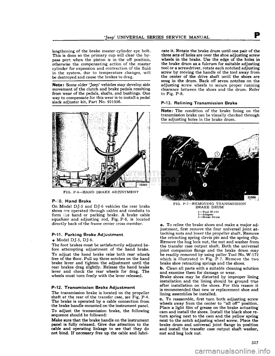
FIG.
P-6—HAND
BRAKE
ADJUSTMENT
P-10.
Hand Brake
On
Model DJ-5 and DJ-6 vehicles the rear brake
shoes
are operated through cables and conduits to
form the hand or parking brake. A brake cable
equalizer and adjusting rod, Fig. P-6, is located directly back of the frame center cross member.
P-11.
Parking Brake Adjustment
•
Model DJ-5, DJ-6.
The
foot
brakes must be satisfactorily adjusted be
fore attempting adjustment of the hand brake.
To
adjust the hand brake raise both rear
wheels
free of the floor.
Pull
up three
notches
on the hand
brake
lever and tighten the adjustment until the
rear
brakes drag slightly. Release the hand brake
lever and check the rear
wheels
for drag. The
wheels
must turn freely with the lever released.
P-12.
Transmission Brake Adjustment
The
transmission brake is located on the propeller
shaft at the rear of the transfer case, see Fig. P-4.
The
brake is operated by a cable connection from
the brake handle mounted on the instrument panel.
To
adjust the transmission brake, the following
sequence
should be followed:
Make
sure that the brake handle on the instrument
panel is fully released. Give due attention to the
cable and operating linkage to see that
they
do
not bind. If necessary free up the cable and
lubri
cate it. Rotate the brake drum until one pair of the
three
sets
of
holes
are over the
shoe
adjusting screw
wheels
in the brake. Use the
edge
of the
holes
in
the brake drum as a fulcrum for suitable adjusting
tool
or a screwdriver, rotate each notched adjusting
screw by moving the handle of the
tool
away from
the center of the drive shaft until the
shoes
are
snug in the drum.
Back
off seven
notches
on the
adjusting screw
wheels
to secure proper running clearance
between
the
shoes
and the drum. Refer
to Fig. P-8.
P-13.
Relining Transmission Brake
Note:
The condition of the brake lining on the
transmission brake can be visually checked through
the adjusting
holes
in the brake drum.
FIG.
P-7—REMOVING
TRANSMISSION
BRAKE
DRUM
1— Tool W-172
2—
Adapter
3—
Brake
Drum
a.
To reline the brake
shoes
and make a major ad
justment, first remove the four universal joint at taching nuts and lower the propeller shaft. Remove
the retracting spring clevis pin and the spring clip.
Remove the hug lock nut, the nut and washer from
the transfer case output shaft. Both the universal
joint companion
flange
and the brake drum may be readily removed by using puller Tool No. W-172
which
is illustrated in Fig. P-7. Remove the two
brake
shoe
retracting springs and the
shoes.
b. Clean all parts with a suitable cleaning solution
and
examine them for damage or wear.
Brake
shoes
may be distorted by improper lining
installation and the lining should be ground true
after installation on the
shoes.
For this reason it
is recommended that new or replacement
shoe
and
lining assemblies be installed.
c. To reassemble, first turn both adjusting screw
wheels
away from the center to "all off" position.
Place a light film of grease on the brake actuating
cam
and install the
shoes.
Install the black
shoe
re
turn
spring next to the cam and the yellow spring next to the notch adjusting wheel screw. Place the
brake
drum and universal joint
flange
in position
and
install the transfer case output shaft washer,
nut and hug lock nut. 327
Page 337 of 376
'Jeep'
UNIVERSAL
SERIES SERVICE
MANUAL
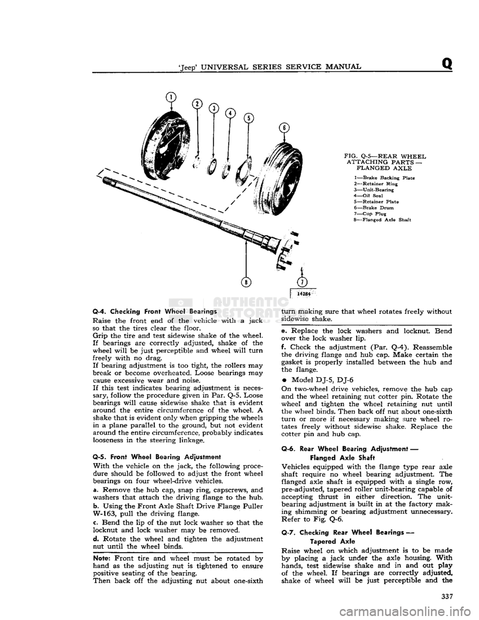
FIG.
Q-5—REAR
WHEEL
ATTACHING
PARTS —
FLANGED
AXLE
1—
Brake
Backing Plate
2—
Retainer
Ring
3—
Unit-Bearing
4—
Oil
Seal
5—
Retainer
Plate 6—
Brake
Drum
7—
Cup
Plug
8—
Flanged
Axle Shaft
14284
Q-4. Checking
Front
Wheel Bearings
Raise
the front end of the vehicle with a
jack
so that the tires clear the floor.
Grip
the tire and
test
sidewise shake of the wheel.
If
bearings are correctly adjusted, shake of the
wheel
will
be just perceptible and wheel
will
turn
freely with no drag.
If
bearing adjustment is too tight, the rollers may
break
or
become
overheated. Loose bearings may cause
excessive
wear and noise.
If
this
test
indicates bearing adjustment is neces
sary,
follow
the procedure given in Par. Q-5. Loose
bearings
will
cause sidewise shake that is evident
around
the entire circumference of the wheel. A shake that is evident only when gripping the
wheels
in
a plane parallel to the ground, but not evident
around
the entire circumference, probably indicates
looseness
in the steering linkage.
Q-5.
Front Wheel Bearing Adjustment
With
the vehicle on the
jack,
the following proce
dure
should be followed to adjust the front wheel
bearings on four wheel-drive vehicles.
a. Remove the hub cap, snap
ring,
capscrews, and
washers that attach the driving
flange
to the hub.
b.
Using the
Front
Axle Shaft Drive Flange Puller
W-163,
pull
the driving flange.
c. Bend the lip of the nut lock washer so that the
locknut
and lock washer may be removed.
d.
Rotate the wheel and tighten the adjustment nut until the wheel binds.
Note:
Front
tire and wheel must be rotated by
hand
as the adjusting nut is
tightened
to ensure positive seating of the bearing.
Then
back off the adjusting nut about one-sixth
turn
making sure that wheel rotates freely without
sidewise shake.
e. Replace the lock washers and locknut. Bend
over the lock washer lip.
f.
Check
the adjustment (Par. Q-4). Reassemble the driving
flange
and hub cap. Make certain the
gasket is properly installed
between
the hub and
the flange.
•
Model DJ-5, DJ-6
On
two-wheel drive vehicles, remove the hub cap
and
the wheel retaining nut cotter pin. Rotate the
wheel and tighten the wheel retaining nut until the wheel binds.
Then
back off nut about one-sixth
turn
or more if necessary making sure wheel ro
tates
freely without sidewise shake. Replace the cotter pin and hub cap.
Q-6.
Rear
Wheel Bearing Adjustment —
Flanged
Axle Shaft
Vehicles
equipped with the
flange
type
rear
axle
shaft require no wheel bearing adjustment. The flanged axle shaft is equipped with a single row,
pre-adjusted,
tapered roller unit-bearing capable of
accepting thrust in either direction. The unit-
bearing
adjustment is built in at the factory mak
ing shimming or bearing adjustment unnecessary.
Refer
to Fig. Q-6.
Q-7.
Checking
Rear
Wheel Bearings —
Tapered
Axle
Raise
wheel on which adjustment is to be made
by placing a
jack
under the axle housing.
With
hands,
test
sidewise shake and in and out play
of the wheel. If bearings are correctly adjusted,
shake of wheel
will
be just perceptible and the 337
Page 343 of 376
'Jeep*
UNIVERSAL
SERIES
SERVICE
MANUAL
R
frame.
This
could cause the already aligned sec
tions of the frame to
become
misaligned or weak ened.
R-3.
Frame Dimensions
Points for measuring frame alignment on vehicles
equipped with the F4
engine
are shown in
Fig.
R-l
and
R-2.
The correct measurements for each model
are
given in the table. Point A is at the front of the
frame.
A-B
and C-D are the distances
between
spring
shackle
bolt and spring pivot bolt frame centers
measured
on a line parallel with the frame center-
line.
E and F show the shackle bolt centers in
rela
tion (above or below) to the pivot bolt centers.
On
vehicles equipped with V6
engines
the frame dimensions are shown in Fig. R-3.
CJ-3B
A-B
44.31"
[112,55
cm.]
C-D
. . . . . .48.48"
[123,14
cm.]
Width
Front
29%" [74,3 cm.]
Width
Rear
29M" [74,3 cm.]
"E"
above .3W [8,18 cm.]
"F"
above 4%* [10,56 cm.]
CJ-5,
CJ-5A,
CJ-6,
CJ-6A,
DJ-5, DJ-6
A-B
.47.08"
[119,58
cm.]
C-D.
52.37"
[133,02
cm.]
Width
Front
2934"
[74,3 cm.]
Width
Rear
29j|" [74,3 cm.]
"E"
above 3%" [8,18 cm.]
"F"
above. .5%" [15,0 cm.]
R-4.
Straightening Frame
In
case the bending or twisting of the frame is not
excessive, it may be straightened.
This
should be
done
cold, as excessive heat applied to the frame
will
weaken it. For this reason it is recommended that badly damaged frame parts be replaced.
Note:
A technique known as "controlled heat" can
be utilized where a frame section is "squashed" and must be brought out without "tearing" or excessive
stretch
to the metal.
R-5.
Front
Axle
Alignment
After
it has been determined that the frame is prop
erly
aligned, the front axle alignment with the
frame
can be checked. The front axle is square
with
the frame if the distance
between
the front
and
rear
axle is the same on both sides. The dis
tance from the spring upper bushings to the front
axle on both sides should be equal.
Note:
Always inspect the springs for broken spring
center
bolts
when checking the frame and axle
alignment.
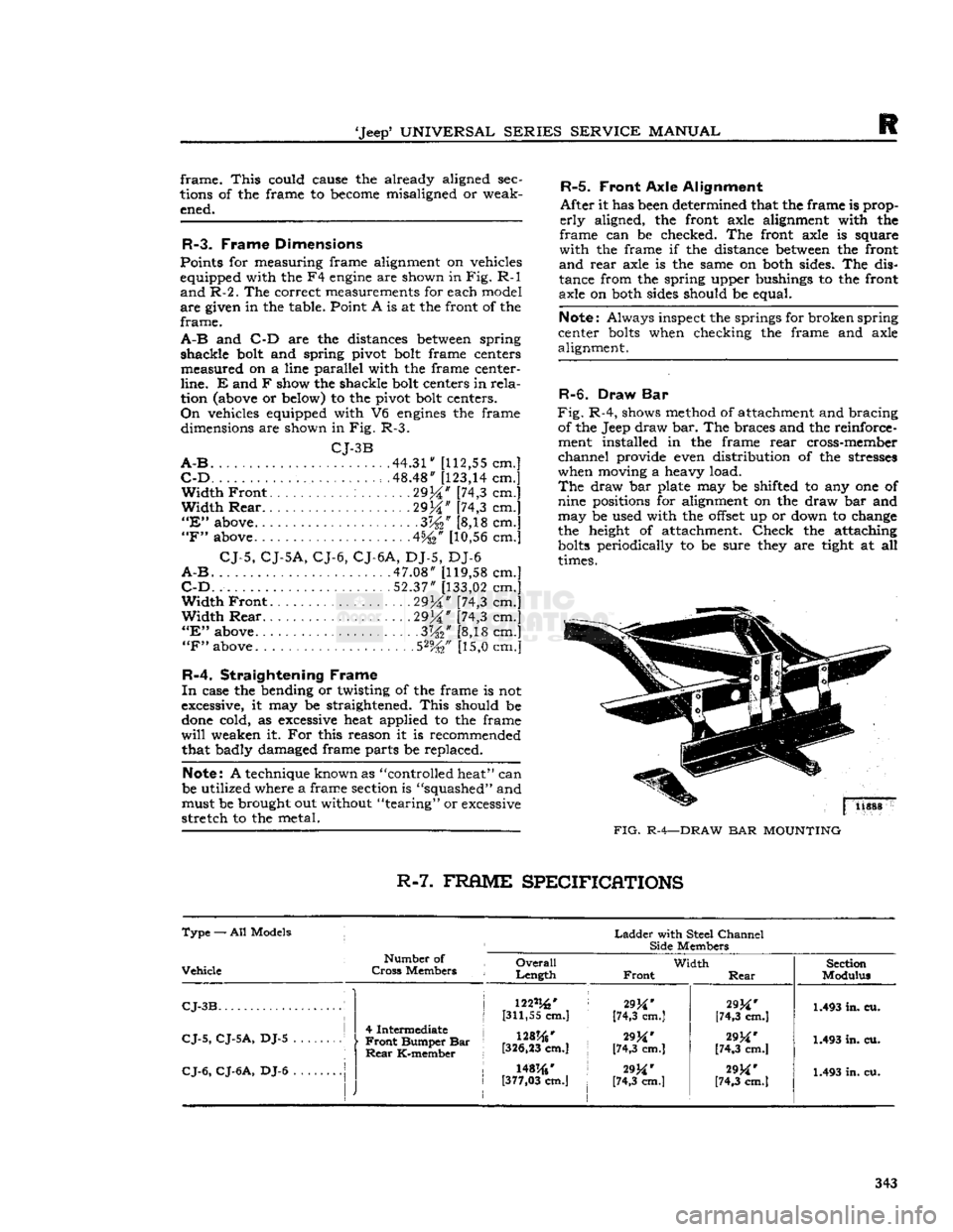
R-6. Draw Bar
Fig.
R-4, shows method of attachment and bracing of the Jeep draw bar. The braces and the reinforce
ment installed in the frame
rear
cross-member
channel
provide even distribution of the stresses
when moving a heavy load.
The
draw bar plate may be shifted to any one of
nine positions for alignment on the draw bar and
may
be used with the
offset
up or down to change
the height of attachment.
Check
the attaching
bolts
periodically to be sure they are tight at all
times.
FIG.
R-4—DRAW
BAR
MOUNTING
R-7.
FRflME
SPECIFICATIONS
Type
— All Models j
Ladder
with Steel
Channel
Side
Members
Vehicle
Number
of
Cross
Members
Overall
Length
Width
Front
Rear
Section
Modulus
CJ-3B
i
CJ-5,
CJ-5A,
DJ-5 1
j
4 Intermediate j
•
Front
Bumper Bar
Rear
K-member 122%'
[311,55 cm.]
128%'
[326,23
cm.] 29^*
[74,3 cm.]
[74,3 cm.]
29M'
[74,3 cm.]
[74,3 cm.] 1.493 in. cu.
1.493 in. cu.
CJ-6,
CJ-6A,
DJ-6
|
J
1
I
r
\mw t
[377,03
cm.]
29M'
[74,3 cm.]
29M'
[74,3 cm.] 1.493 in. cu.
343
Page 357 of 376
'Jeep'
UNIVERSAL SERIES SERVICE
MANUAL
u
MISCEIiLaNEOUS
Contents
SUBJECT
PAR.
Abbreviations
U-15
Extra
Equipment U-2
Front
Bumper Weight U-9
Governor
U-3
Governor
Adjustment U-4
Governor
Maintenance. U-6
U-1. GENERAL
Miscellaneous information included in this sectioi
includes coverage of extra equipment, special
tools,
torque specifications, and charts and tables.
U-2. EXTRA
EQUIPMENT
Much
of the utility of the
*
Jeep*
Universal
is due to
the extra equipment which has been designed to adapt it for farming and industry. The mainte
nance and use of
some
of this equipment is out
lined
in this section.
U-3.
Governor Assembly
The
Novi governor is supplied for models equipped
with
the F4 engine.
This
is a centrifugal type governor and is illustrated in Fig. U-2. Complete
installation
instructions are supplied with each
assembly. Adjustment and operating procedures
are
given below.
U-4.
Governor Adjustment
a.
Adjust the carburetor to obtain smooth
engine
idle at 600 rpm., then
stop
the engine.
b.
Check
throttle linkage to ensure maximum
throttle opening. Be certain that throttle and
governor linkage is free.
c.
Place the carburetor throttle in wide-open posi tion and
pull
the governor control handle out to
the last notch. Adjust the governor to bellcrank
rod
so that the linkage
will
hold the carburetor
throttle in wide-open position.
d.
Close the governor control and start the
engine
Again
pull
the control out to the last notch and
adjust
the length of the cable at adjusting yoke so
that the
engine
will
run at
2600
rpm. Close the
control
to recheck the linkage for free action and
to make sure the
engine
will
return to 600 rpm.
idle speed.
If
the
engine
runs faster than this speed,
loosen
the lock nut which locks the governor hand control
handle on the dash to the rod and back off the
handle until the carburetor idle speed adjusting
screw
bears on the stop. Tighten the lock nut.
In
the absence of electrical tachometer equipment,
engine
speed may be determined by the speedom
eter. Safely
jack
up the
rear
wheels and be sure the front wheel drive is not
engaged.
When driving
the
rear
wheels in high or direct transmission gear,
the
speedometer
will
read from 13j^ to 15 mph. [21.6 to 24.0 kph.] at an
engine
speed of from 900
to 1000 rpm.
SUBJECT
PAR.
Heater
U-10 Miscellaneous Data U-16
Pintle
Hook 1X7
Special
Tools. U-ll
Torque
Specifications U-13, 14, 15
Standard
and Recommended Tools
j.
.U-12
U-5.
Novi Governor Operation /
The
Novi governor is directly belted to the F4
engine
as no clutch is provided to disconnect the
drive.
To
operate the vehicle
WITHOUT
governor con
trol,
push the governor hand control all the way
IN
against the instrument panel.
To
operate the vehicle
WITH
governor control,
pull
the governor hand control handle out. The
hand
control has nine notched positions. Pulling the
control
out to the first notch
sets
the controlled
engine
speed at approximately 1000 rpm. and each successive notch increases the speed 200 rpm.
until
2600
rpm. is reached in the ninth notch. The
hand
control may be released by turning the han dle one-quarter
turn
in either direction.
When
the
engine
is being operated under governor
control
(hand control out) the controlled
engine
speed may be
exceeded
at any time by depressing
the
foot
accelerator in the conventional manner to
secure a greater carburetor throttle opening than
that determined by the governor hand control
setting.
U-6.
Governor Maintenance
The
belt tension may be adjusted by raising or
lowering the governor in the slotted
holes
in the mounting bracket. Keep the pulleys and belt free
of
dirt
and oil. Belt slippage
will
affect governor
operation and a tight belt may cause
rapid
wear
of the governor shaft and bearings. Adjust it to
allow Yi' [12,7 mm.] depression midway
between
the pulleys with thumb pressure.
There
is little wear of the internal parts for they
operate in oil. The governor housings are equipped
with
both
fill
and
drain
plugs and also with level
indicating
plugs.
Check
the oil level at each vehicle
lubrication
and change the oil each time the en
gine
oil is changed using the same grade oil used
in
the engine.
Caution:
Do not
fill
the governor housing above
the level plug. Overfilling
will
prevent governor
control
and possibly cause damage to governor in
ternal
parts. The capacity of
these
governors is two fluid ounces [59,15 cm3]. The filler plug is
also a vent which should be cleaned thoroughly at
each oil change to be sure that the vent operates.
U-7.
Pintle Hook
The
standard type pintle hook, Fig. U-1, affords a
safe, easy hitch for towing a
trailer
or other vehicle. 357
Page 360 of 376
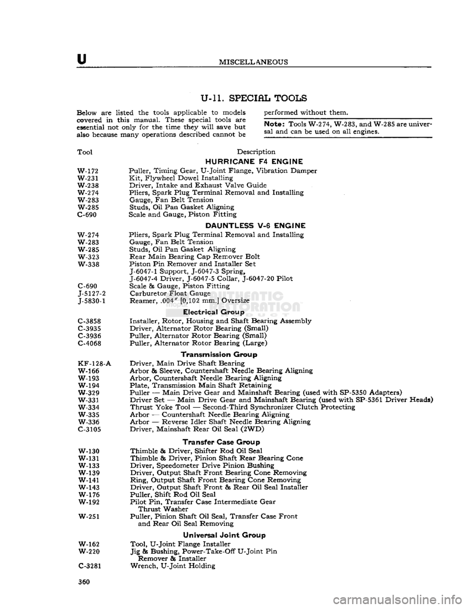
u
MISCELLANEOUS
U-ll. SPECIAL TOOLS
Below are listed the
tools
applicable to
models
covered in this manual. These special
tools
are
essential not
only
for the
time
they
will
save
but
also
because
many
operations
described cannot be performed
without
them.
Note;
Tools W-274, W-283, and W-285 are univer
sal
and can be used on all
engines.
Tool
Description
HURRICANE
F4
ENGINE
W-172 Puller, Timing
Gear,
U-Joint Flange, Vibration Damper W-231 Kit, Flywheel Dowel Installing
W-238 Driver, Intake and Exhaust Valve Guide
W-2
74 Pliers, Spark Plug Terminal Removal and Installing W-283 Gauge, Fan Belt Tension W-285 Studs, Oil Pan Gasket Aligning
C-690 Scale and Gauge, Piston Fitting
DAUNTLESS
V-6
ENGINE
W-274 Pliers, Spark Plug Terminal Removal and Installing
W-283 Gauge, Fan Belt Tension W-285 Studs, Oil Pan Gasket Aligning W-323
Rear
Main Bearing Cap Remover Bolt
W-338 Piston Pin Remover and Installer Set
J-6047-1
Support, J-6047-3 Spring,
J-6047-4
Driver, J-6047-5
Collar,
J-6047-20
Pilot
C-690 Scale & Gauge, Piston Fitting
J-5127-2 Carburetor Float Gauge
J-5830-1
Reamer, .004"
[0,102
mm.] Oversize
Electrical
Group
C-3858 Installer, Rotor, Housing and Shaft Bearing Assembly
C-3935 Driver, Alternator Rotor Bearing (Small) C-3936 Puller, Alternator Rotor Bearing (Small)
C-4068 Puller, Alternator Rotor Bearing (Large)
Transmission
Group
KF-128-A
Driver, Main Drive Shaft Bearing W-166 Arbor &
Sleeve,
Countershaft
Needle
Bearing Aligning
W-193 Arbor, Countershaft
Needle
Bearing Aligning W-194 Plate, Transmission Main Shaft Retaining
W-329 Puller — Main Drive
Gear
and Mainshaft Bearing (used with SP-5350 Adapters)
W-331 Driver Set — Main Drive
Gear
and Mainshaft Bearing (used with SP-5361 Driver Heads)
W-334 Thrust Yoke Tool — Second-Third Synchronizer Clutch Protecting W-335 Arbor — Countershaft
Needle
Bearing Aligning
W-336 Arbor — Reverse Idler Shaft
Needle
Bearing Aligning
C-3105 Driver, Mainshaft
Rear
Oil Seal (2WD)
Transfer Case
Group
W-130 Thimble & Driver, Shifter Rod Oil Seal
W-131 Thimble & Driver, Pinion Shaft
Rear
Bearing Cone
W-133 Driver,
Speedometer
Drive Pinion Bushing W-139 Driver, Output Shaft Front Bearing Cone Removing
W-141 Ring, Output Shaft Front Bearing Cone Removing
W-143 Driver, Output Shaft Front &
Rear
Oil Seal Installer W-176 Puller, Shift Rod Oil Seal
W-192 Pilot Pin, Transfer Case Intermediate
Gear
Thrust
Washer
W-251 Puller, Pinion Shaft Oil Seal, Transfer Case Front and
Rear
Oil Seal Removing
Universal
Joint Group
W-162 Tool, U-Joint Flange Installer
W-220 Jig & Bushing, Power-Take-Off U-Joint Pin Remover & Installer
C-3281 Wrench, U-Joint Holding 360